Loading ...
Loading ...
Loading ...
36
10 1/4”
1/2”
19
1/2
” - 26
9/16
” - 32
7/8
”
EN
7
7
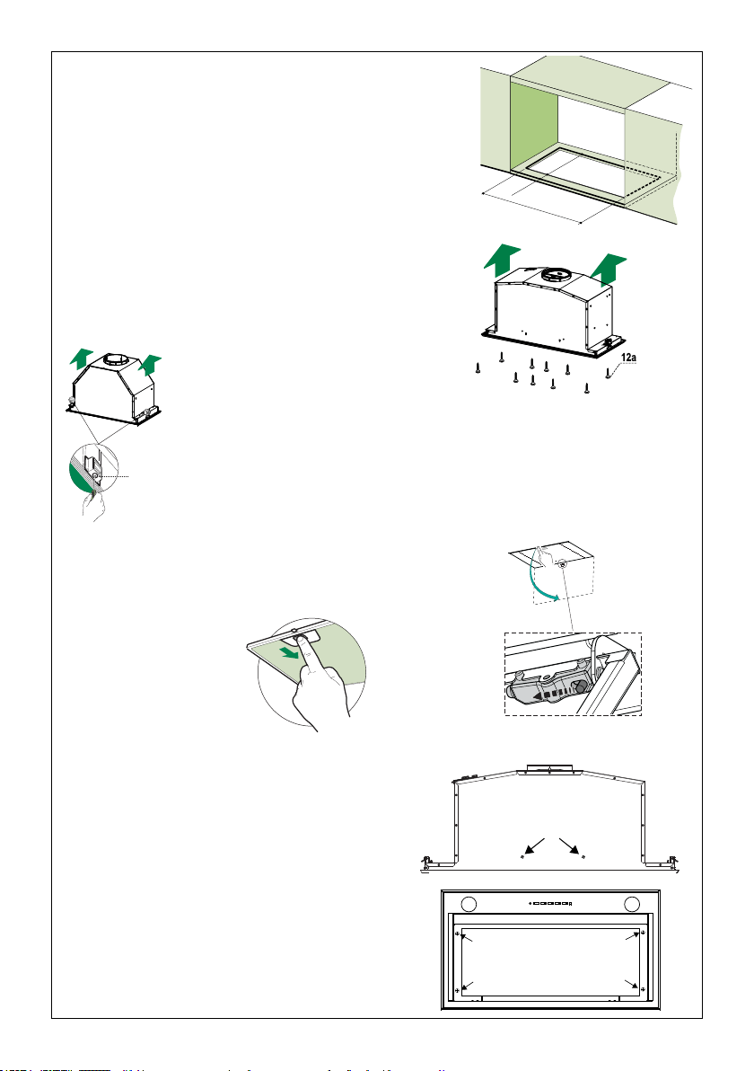
INSTALLATION
Fitting the Hood canopy
BEFORE FITTING THE HOOD TO THE WALL UNIT, PROCEED AS FOLLOWS:
• Disconnect the wires to the Commands at the connectors.
• Disconnect the wires to the Light at the con-
nectors.
• The Hood can be installed directly on the
underside of
the wall unit (Minimum 650 mm
from the Cooker Hob).
• Create an opening in the bottom of the wall unit,
as shown.
• Insert the hood until the side supports snap into
place.
• Fasten using the 10 screws 12a provided.
• Lock in position by tightening the screws Vf from
underneath the hood.
• Open the suction panel by turning the specific knob.
• Disconnect the panel from the hood canopy by sliding the
fixing pin lever.
• Remove grease filters.
• Screw the Frame into place
using the 6 scr
ews 12f, re-
connect the wires to the
Commands and Light, re-
place the metal grease filter
and the Panel.
260
13
495 - 675
EN
7
7
INSTALLATION
Fitting the Hood canopy
BEFORE FITTING THE HOOD TO THE WALL UNIT, PROCEED AS FOLLOWS:
• Disconnect the wires to the Commands at the connectors.
• Disconnect the wires to the Light at the con-
nectors.
• The Hood can be installed directly on the
underside of
the wall unit (Minimum 650 mm
from the Cooker Hob).
• Create an opening in the bottom of the wall unit,
as shown.
• Insert the hood until the side supports snap into
place.
• Fasten using the 10 screws 12a provided.
• Lock in position by tightening the screws Vf from
underneath the hood.
• Open the suction panel by turning the specific knob.
• Disconnect the panel from the hood canopy by sliding the
fixing pin lever.
• Remove grease filters.
• Screw the Frame into place
using the 6 scr
ews 12f, re-
connect the wires to the
Commands and Light, re-
place the metal grease filter
and the Panel.
260
13
495 - 675
Vf
La campana se puede instalar directamente en la parte inferior de la
unidad de pared (mínimo 24 "-30" desde la supercie de cocción).
Crear una abertura en la parte inferior de la unidad de pared,
como se muestra.
Inserte la campana hasta que los soportes laterales encajen en su lugar.
Sujete usando los 10 tornillos12aprovistos.
Bloquee la posición apretando los tornillos Vf desde debajo de la campana.
Abra el panel de la tapa del ltro girando la perilla especíca.
Desconecte el panel de la cobertura de la campana deslizando las
palancas de los pasadores de jación.
Atornille el marco en su lugar con los 6 tornillos
12f(1/8"x5/16" torx), vuelva a conectar los
alambres al conector y
el cable de tierra eléctrico
(Amarillo/Verde) retirado previamente. V
uelva a
colocar el ltro de grasa de metal y el panel.
Retire los ltros de grasa
y déjelos aparte.
Loading ...
Loading ...
Loading ...