
Welcome
Congratulations on your purchase of a new
Honda motorcycle. Your selection of a
Honda makes you part of a worldwide family
of satisfied customers who appreciate
Honda's reputation for building quality into
every product.
To ensure your safety and riding pleasure:
● Read this owner's manual carefully.
● Follow all recommendations and
procedures contained in this manual.
● Pay close attention to safety messages
contained in this manual and on the
motorcycle.
To protect your investment, we urge you to
take responsibility for keeping your
motorcycle well serviced and maintained.
Also, observe the break-in guidelines, and
always perform the pre-ride inspection and
other periodic checks in this manual.
When service is required, remember that
your Honda dealer knows your motorcycle
best. If you have the required mechanical
“know-how” and tools, you can purchase an
official Honda Service Manual to help you
perform many maintenance and repair tasks.
2 P. 217
Read the warranty information thoroughly so
that you understand the warranty coverage
and that you are aware of your rights and
responsibilities. 2 P. 218
You may also want to visit our website at
www.powersports.honda.com.
Canada
www.honda.ca.
Happy riding!
20170830152249_31MKF6100_enu_BOOK Page 2 Wednesday, August 30 2017 15:45:50 JST
A Few Words About Safety
Your safety, and the safety of others, is very
important. Operating this motorcycle safely is
an important responsibility.
To help you make informed decisions about
safety, we have provided operating
procedures and other information on safety
labels and in this manual. This information
alerts you to potential hazards that could
hurt you or others.
Of course, it is not practical or possible to
warn you about all hazards associated with
operating or maintaining a motorcycle. You
must use your own good judgment.
You will find important safety information in a
variety of forms, including:
● Safety labels on the motorcycle
●
Safety Messages preceded by a safety alert
symbol and one of three signal words:
DANGER, WARNING, or CAUTION.
These signal words mean:
3DANGER
You WILL be KILLED or SERIOUSLY
HURT if you don’t follow instructions.
3WARNING
You CAN be KILLED or SERIOUSLY
HURT if you don’t follow instructions.
3CAUTION
You CAN be HURT if you don’t follow
instructions.
Other important information is
provided under the following titles:
NOTICE
Information to help you avoid
damage to your motorcycle,
other property, or the
environment.
20170830152249_31MKF6100_enu_BOOK Page 3 Wednesday, August 30 2017 15:45:50 JST

Safety Guidelines.................................................P. 3
Safety Labels.......................................................
..P. 8
Safety Precautions............................................. P. 10
Riding Precautions............................................ P. 12
Accessories & Modifications...........................P. 16
Loading ................................................................ P. 17
20170830152249_31MKF6100_enu_BOOK Page 5 Wednesday, August 30 2017 15:45:50 JST
This section contains important information for safe riding of your motorcycle.
Please read this section carefully.
Motorcycle Safety

Safety Guidelines
Follow these guidelines to enhance your safety:
● Perform all routine and regular inspections
specified in this manual.
● Stop the engine and keep sparks and flame
away before filling the fuel tank.
● Do not run the engine in enclosed or partly
enclosed areas. Carbon monoxide in
exhaust gases is toxic and can kill you.
Always Wear a Helmet
It's a proven fact: helmets and protective
apparel significantly reduce the number and
severity of head and other injuries. So always
wear an approved motorcycle helmet and
protective apparel. 2 P. 10
Before Riding
Make sure that you are physically fit, mentally
focused and free of alcohol and drugs.
CBR1000RR/RA
Check that you and your passenger are both
wearing an approved motorcycle helmet and
protective apparel. Instruct your passenger on
holding onto the seat strap or your waist,
leaning with you in turns, and keeping their feet
on the footpegs, even when the motorcycle is
stopped.
CBR1000S1/S2
Check that you are wearing an approved
motorcycle helmet and protective apparel.
20170830152249_31MKF6100_enu_BOOK Page 6 Wednesday, August 30 2017 15:45:50 JST
Safety Guidelines
Motorcycle Safety
3
Continued

Take Time to Learn & Practice
Even if you have ridden other motorcycles,
practice riding in a safe area to become familiar
with how this motorcycle works and handles,
and to become accustomed to the motorcycle's
size and weight.
We recommend that all riders take a certified
course approved by the Motorcycle Safety
Foundation (MSF). New riders should start with
the basic course, and even experienced riders
will find the advanced course beneficial.
For information about the MSF training course
nearest you, call the national toll-free number:
(800) 446-9227.
USA
Other riding tips can be found in the You
and Your Motorcycle Riding Tips booklet that
came with your motorcycle.
Ride Defensively
Always pay attention to other vehicles around
you, and do not assume that other drivers see
you. Be prepared to stop quickly or perform an
evasive maneuver.
Make Yourself Easy to See
Make yourself more visible, especially at night,
by wearing bright reflective clothing, positioning
yourself so other drivers can see you, signaling
before turning or changing lanes, and using
your horn when necessary.
20170830152249_31MKF6100_enu_BOOK Page 7 Wednesday, August 30 2017 15:45:50 JST
Safety Guidelines
Motorcycle Safety
4

Ride within Your Limits
Never ride beyond your personal abilities or
faster than conditions warrant. Fatigue and
inattention can impair your ability to use good
judgment and ride safely.
Never Carry a passenger
CBR1000S1/S2
There are no handholds, seat, or footrests to
carry a passenger.
Don't Drink and Ride
Alcohol and riding don't mix. Even one alcoholic
drink can reduce your ability to respond to
changing conditions, and your reaction time
gets worse with every additional drink. Don't
drink and ride, and don't let your friends drink
and ride either.
Keep Your Honda in Safe Condition
It's important to keep your motorcycle properly
maintained and in safe riding condition.
Inspect your motorcycle before every ride and
perform all recommended maintenance. Never
exceed load limits (2 P. 17), and do not modify
your motorcycle or install accessories that
would make your motorcycle unsafe (2 P. 16).
20170830152249_31MKF6100_enu_BOOK Page 8 Wednesday, August 30 2017 15:45:50 JST
Safety Guidelines
Motorcycle Safety
5
Continued

If You are Involved in a Crash
Personal safety is your first priority. If you or
anyone else has been injured, take time to
assess the severity of the injuries and whether it
is safe to continue riding. Call for emergency
assistance if needed. Also follow applicable laws
and regulations if another person or vehicle is
involved in the crash.
If you decide to continue riding, first turn the
ignition switch to the OFF position, and evaluate
the condition of your motorcycle. Inspect for
fluid leaks, check the tightness of critical nuts
and bolts, and check the handlebars, control
levers, brakes, and wheels. Ride slowly and
cautiously.
Your motorcycle may have suffered damage
that is not immediately apparent. Have your
motorcycle thoroughly checked at a qualified
service facility as soon as possible.
Lithium-Ion (Li-Ion) Battery
CBR1000S1/S2
If you smell an unusual odor coming from the
lithium-ion (li-ion) battery, park your motorcycle
in a safe place outside and away from
flammable objects, then turn the ignition switch
to the OFF position. Have your motorcycle
inspected by your dealer immediately.
20170830152249_31MKF6100_enu_BOOK Page 9 Wednesday, August 30 2017 15:45:50 JST
Safety Guidelines
Motorcycle Safety
6

Carbon Monoxide Hazard
Exhaust contains poisonous carbon monoxide, a
colorless, odorless gas. Breathing carbon
monoxide can cause loss of consciousness and
may lead to death.
If you run the engine in confined or even partly
enclosed area, the air you breathe could
contain a dangerous amount of carbon
monoxide.
Never run your motorcycle inside a garage or
other enclosure.
3WARNING
Running the engine of your motorcycle
while in an enclosed or even partially
enclosed area can cause a rapid build-
up of toxic carbon monoxide gas.
Breathing this colorless, odorless gas
can quickly cause unconsciousness and
lead to death.
Only run your motorcycle's engine
when it is located in a well ventilated
area outdoors.
20170830152249_31MKF6100_enu_BOOK Page 10 Wednesday, August 30 2017 15:45:50 JST
Safety Guidelines
Motorcycle Safety
7
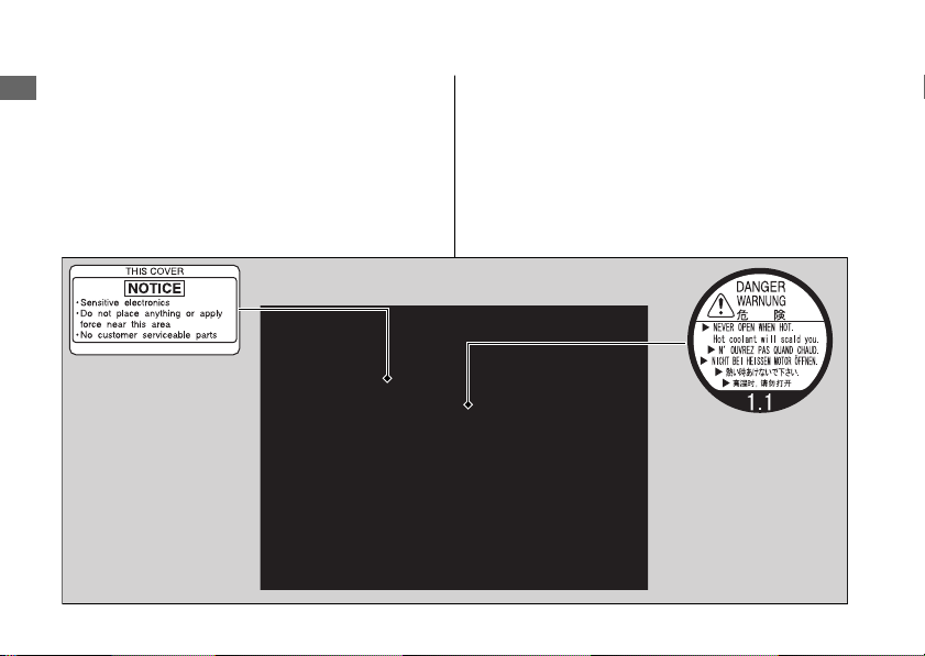
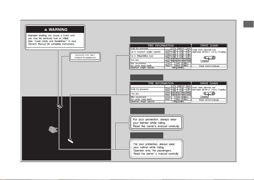
Safety Labels
Safety and information labels on your
motorcycle provide important safety
information and may warn you of potential
hazards that could cause serious injury. Read
these labels carefully and don't remove them.
If a label comes off or becomes hard to read,
contact your dealer for a replacement.
20170830152249_31MKF6100_enu_BOOK Page 11 Wednesday, August 30 2017 15:45:50 JST
Safety Labels
Motorcycle Safety
8
20170830152249_31MKF6100_enu_BOOK Page 12 Wednesday, August 30 2017 15:45:50 JST
Safety Labels
Motorcycle Safety
9
CBR1000S1/S2
CBR1000S1/S2
CBR1000RR/RA
CBR1000RR/RA

Safety Precautions
● Ride cautiously and keep your hands on the
handlebars and feet on the footpegs.
●
CBR1000RR/RA
Keep passenger’s hands onto the seat strap
or your waist, passenger’s feet on the
footpegs while riding.
●
CBR1000RR/RA
Always consider the safety of your
passenger, as well as other drivers and
riders.
CBR1000S1/S2
Always consider the safety of other drivers
and riders.
Protective Apparel
CBR1000RR/RA
Make sure that you and any passenger are
wearing an approved motorcycle helmet, eye
protection, and high-visibility protective
clothing. Ride defensively in response to
weather and road conditions.
CBR1000S1/S2
Make sure that you are wearing an approved
motorcycle helmet, eye protection, and high-
visibility protective clothing. Ride defensively in
response to weather and road conditions.
#
Helmet
Should be safety-standard certified, high-
visibility, and correct size for your head
● Must fit comfortably but securely, with the
chin strap fastened.
● Face shield with unobstructed field of vision
or other approved eye protection
20170830152249_31MKF6100_enu_BOOK Page 13 Wednesday, August 30 2017 15:45:50 JST
Safety Precautions
Motorcycle Safety
10
USA
Look for a DOT (Department of
Transportation) certification label on any helmet
you buy.
CBR1000RR/RA
3WARNING
Not wearing a helmet increases the
chance of serious injury or death in a
crash.
Make sure that you and any passenger
always wear an approved helmet and
protective apparel.
CBR1000S1/S2
3WARNING
Not wearing a helmet increases the
chance of serious injury or death in a
crash.
Make sure that you always wear an
approved helmet and protective
apparel.
#
Gloves
Full-finger leather gloves with high abrasion
resistance
#
Boots or Riding Shoes
Sturdy boots with non-slip soles and ankle
protection
#
Jacket and Pants
Protective, highly visible, long-sleeved jacket
and durable long pants for riding (or a
protective suit)
20170830152249_31MKF6100_enu_BOOK Page 14 Wednesday, August 30 2017 15:45:50 JST
Safety Precautions
Motorcycle Safety
11

Riding Precautions
Break-in Period
During the first 300 miles (500 km) of running,
follow these guidelines to ensure your
motorcycle's future reliability and performance.
● Avoid full-throttle starts and rapid
acceleration.
● Avoid hard braking and rapid down-shifts.
● Ride conservatively.
Brakes
Observe the following guidelines:
● Avoid excessively hard braking and
downshifting.
u Sudden braking can reduce the
motorcycle's stability.
u Where possible, reduce speed before
turning; otherwise you risk sliding out.
● Exercise caution on low traction surfaces.
u The tires slip more easily on such
surfaces and braking distances are
longer.
● Avoid continuous braking.
u Repeated braking, such as when
descending long, steep slopes can
seriously overheat the brakes, reducing
their effectiveness. Use engine braking
with intermittent use of the brakes to
reduce speed.
● For full braking effectiveness, operate both
the front and rear brakes together.
20170830152249_31MKF6100_enu_BOOK Page 15 Wednesday, August 30 2017 15:45:50 JST
Riding Precautions
Motorcycle Safety
12

#
Anti-lock Brake System (ABS)
CBR1000RA/S1/S2
This model is equipped with an Anti-lock Brake
System (ABS) designed to help prevent the
brakes from locking up during hard braking.
The ABS functions with information provided by
the IMU (Inertia Measurement Unit).
● ABS does not reduce braking distance. In
certain circumstances, ABS may result in a
longer stopping distance.
● ABS does not function at speeds below 4
mph (6 km/h).
● The brake lever and pedal may recoil slightly
when applying the brakes. This is normal.
● Always use the recommended front/rear
tires and sprockets to ensure correct ABS
operation.
#
Engine Braking
Engine braking helps slow your motorcycle
down when you release the throttle. For further
slowing action, downshift to a lower gear. Use
engine braking with intermittent use of the
brakes to reduce speed when descending long,
steep slopes.
#
Wet or Rainy Conditions
Road surfaces are slippery when wet, and wet
brakes further reduce braking efficiency.
Exercise extra caution when braking in wet
conditions.
If the brakes get wet, apply the brakes while
riding at low speed to help them dry.
20170830152249_31MKF6100_enu_BOOK Page 16 Wednesday, August 30 2017 15:45:50 JST
Riding Precautions
Motorcycle Safety
13
Continued

Parking
● Park on a firm, level surface.
● If you must park on a slight incline or loose
surface, park so that the motorcycle cannot
move or fall over.
● Make sure that high-temperature parts
cannot come into contact with flammable
materials.
● Do not touch the engine, muffler, brakes
and other high-temperature parts until they
cool down.
● To reduce the likelihood of theft, always lock
the handlebars and remove the key when
leaving the motorcycle unattended.
Use of an anti-theft device is also
recommended.
#
Parking with the Side Stand
1.
Stop the engine.
2.
Push the side stand down.
3.
Slowly lean the motorcycle to the left until its
weight rests on the side stand.
4.
Turn the handlebars fully to the left.
u Turning the handlebars to the right
reduces stability and may cause the
motorcycle to fall.
5.
Turn the ignition switch to the LOCK
position and remove the key. 2 P. 100
Refueling and Fuel Guidelines
Follow these guidelines to protect the engine,
fuel system and catalytic converter:
● Use only unleaded gasoline.
● Use recommended octane number. Using
lower octane gasoline will result in
decreased engine performance.
● Do not use fuels containing a high
concentration of alcohol. 2 P. 216
● Do not use stale or contaminated gasoline
or an oil/gasoline mixture.
● Avoid getting dirt or water in the fuel tank.
20170830152249_31MKF6100_enu_BOOK Page 17 Wednesday, August 30 2017 15:45:50 JST
Riding Precautions
Motorcycle Safety
14

Honda selectable torque control
When the Honda selectable torque control
(Torque Control) detects rear wheel spin during
acceleration, the system will limit the amount of
torque applied to the rear wheel based on the
Torque Control level selected.
Additionally, the system ease the rapid motion
during the wheelie when accelerating based on
the Torque Control level selected.
Torque Control will allow some wheel spin
during acceleration at the lower Torque Control
levels settings. Select a level that is appropriate
for your skill and riding conditions.
Torque Control does not work during
deceleration and will not prevent the rear wheel
from skidding due to engine braking. Do not
close the throttle suddenly, especially when
riding on slippery surfaces.
Torque Control may not compensate for rough
road conditions or rapid throttle operation.
Always consider road and weather conditions,
as well as your skills and condition, when
applying throttle.
If your motorcycle gets stuck in mud, snow or
sand, it may be easier to free it by turning off
the Torque Control temporarily.
Temporarily turning off Torque Control also
may help you maintain control and balance
when riding on off-road terrain.
Always use the recommended tires and
sprockets to ensure correct Torque Control
operation.
20170830152249_31MKF6100_enu_BOOK Page 18 Wednesday, August 30 2017 15:45:50 JST
Riding Precautions
Motorcycle Safety
15
Accessories &
Modifications
We strongly advise that you do not add any
accessories that were not specifically designed
or approved for your motorcycle by Honda or
make modifications to your motorcycle from its
original design. Doing so can make it unsafe.
Modifying your motorcycle may also void your
warranty and make your motorcycle illegal to
operate on public roads and highways. Before
deciding to install accessories on your
motorcycle be certain the modification is safe
and legal.
3WARNING
Improper accessories or modifications
can cause a crash in which you can be
seriously hurt or killed.
Follow all instructions in this owner's
manual regarding accessories and
modifications.
Do not pull a trailer with, or attach a sidecar to,
your motorcycle. Your motorcycle was not
designed for these attachments, and their use
can seriously impair your motorcycle's handling.
CBR1000S1/S2
Do not attempt modify the motorcycle to carry
a passenger. The subframe was not designed to
carry the additional weight of a passenger.
20170830152249_31MKF6100_enu_BOOK Page 19 Wednesday, August 30 2017 15:45:50 JST
Accessories & Modifications
Motorcycle Safety
16
Loading
●
CBR1000S1/S2
Never carry a passenger. Your motorcycle
was not designed to carry a passenger.
● Carrying extra weight affects your
motorcycle's handling, braking and stability.
Always ride at a safe speed for the load you
are carrying.
● Avoid carrying an excessive load and keep
within specified load limits.
Maximum weight capacity 2 P. 223
● Tie all luggage securely, evenly balanced
and close to the center of the motorcycle.
● Do not place objects near the lights or the
muffler.
CBR1000RR/RA
3WARNING
Overloading or improper loading can
cause a crash and you can be seriously
hurt or killed.
Follow all load limits and other loading
guidelines in this manual.
CBR1000S1/S2
3WARNING
Overloading improper loading or
carrying a passenger can cause a crash
and you can be seriously hurt or killed.
Follow all load limits and other loading
guidelines in this manual.
20170830152249_31MKF6100_enu_BOOK Page 20 Wednesday, August 30 2017 15:45:50 JST
Loading
Motorcycle Safety
17
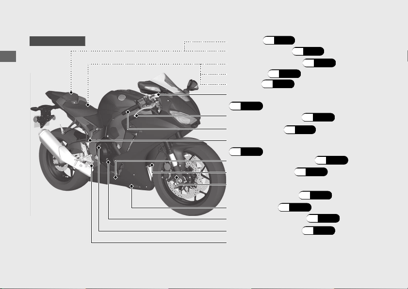
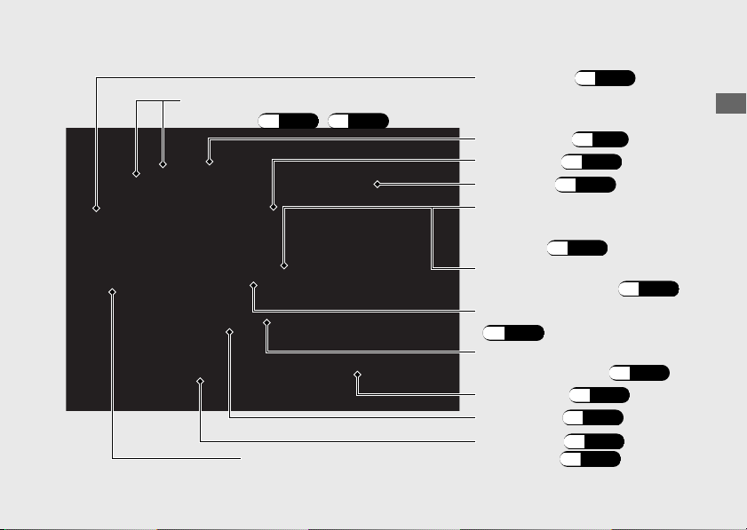
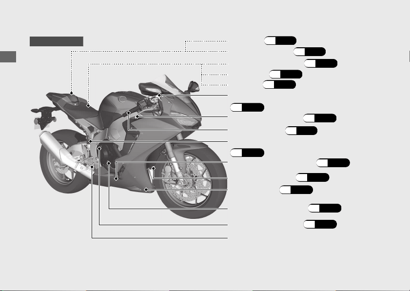
Parts Location
20170830152249_31MKF6100_enu_BOOK Page 21 Wednesday, August 30 2017 15:45:50 JST
Operation Guide
18
Main fuse/FI fuse
(P.198)
Front brake lever (P.163)
Throttle grip (P.161)
Rear brake fluid reservoir
(P.149)
Rear brake pedal
Engine oil filter (P.145)
Engine oil fill cap (P.143)
Engine oil dipstick (P.143)
Tool kit (P.113)
Document bag (P.113)
Engine oil drain bolt (P.145)
Fuse box (P.197)
Battery (P.137)
Front brake fluid reservoir
(P.149)
Front suspension spring
preload adjuster (P.164)
CBR1000RR/RA
Under cowl
(P.142)
20170830152249_31MKF6100_enu_BOOK Page 22 Wednesday, August 30 2017 15:45:50 JST
Operation Guide
19
Continued
Clutch lever
(P.157)
Rear suspension spring
preload adjuster (P.167)
Drive chain (P.153)
Side stand
(P.152)
Shift lever (P.109)
Front suspension rebound damping/compression damping
adjusters
(P.165) (P.166)
Front seat (P.139)
Coolant reserve tank
(P.147)
Fuel fill cap (P.111)
Rear seat (P.140)
Rear suspension
compression damping
adjuster
(P.169)
Rear suspension
rebound
damping adjuster
(P.168)
Front suspension spring preload adjuster (P.164)
20170830152249_31MKF6100_enu_BOOK Page 23 Wednesday, August 30 2017 15:45:50 JST
Operation Guide
20
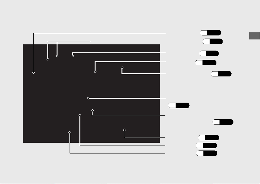
Parts Location (Continued)
Main fuse/FI fuse
(P.198)
Front brake lever (P.163)
Throttle grip (P.161)
Rear brake fluid reservoir
(P.149)
Rear brake pedal
Engine oil filter (P.145)
Engine oil fill cap (P.143)
Engine oil dipstick (P.143)
Tool kit (P.113)
Document bag (P.113)
Engine oil drain bolt (P.145)
Fuse box (P.197)
Battery (P.137)
Front brake fluid reservoir
(P.149)
CBR1000S1/S2
Under cowl
(P.142)
20170830152249_31MKF6100_enu_BOOK Page 24 Wednesday, August 30 2017 15:45:50 JST
Operation Guide
21
Clutch lever
(P.157)
Drive chain
(P.153)
Side stand
(P.152)
Shift lever
(P.109)
Front seat (P.139)
Coolant reserve tank
(P.147)
Fuel fill cap (P.111)
Single seat cowl (P.141)
Front suspension spring preload adjusters (P.171)
Rear suspension spring
preload adjuster (P.173)
Instruments
20170830152249_31MKF6100_enu_BOOK Page 25 Wednesday, August 30 2017 15:45:50 JST
Operation Guide
22
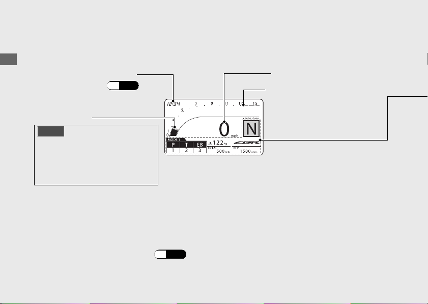
Display Check
When the ignition switch is turned to the ON position, the opening symbol will show on the
display. If the display itself does not shows when it should, have your dealer check for
problems.
Street mode
Clock (12-hour display)
To set the clock:
(P.70)
Speedometer
Tachometer
NOTICE
Do not operate the engine in the
tachometer red zone. Excessive
engine speed can adversely affect
engine life.
You can select the street mode or circuit mode display.
To change the circuit mode:
(P.24)
Tachometer red zone
(excessive engine rpm range)
A1321
P
T SEB
QS OFF
20170830152249_31MKF6100_enu_BOOK Page 26 Wednesday, August 30 2017 15:45:50 JST
Operation Guide
23
Continued
Shows 1st to 6th gear positions. “-”appears
when the transmission is not shifted properly.
Gear position indicator
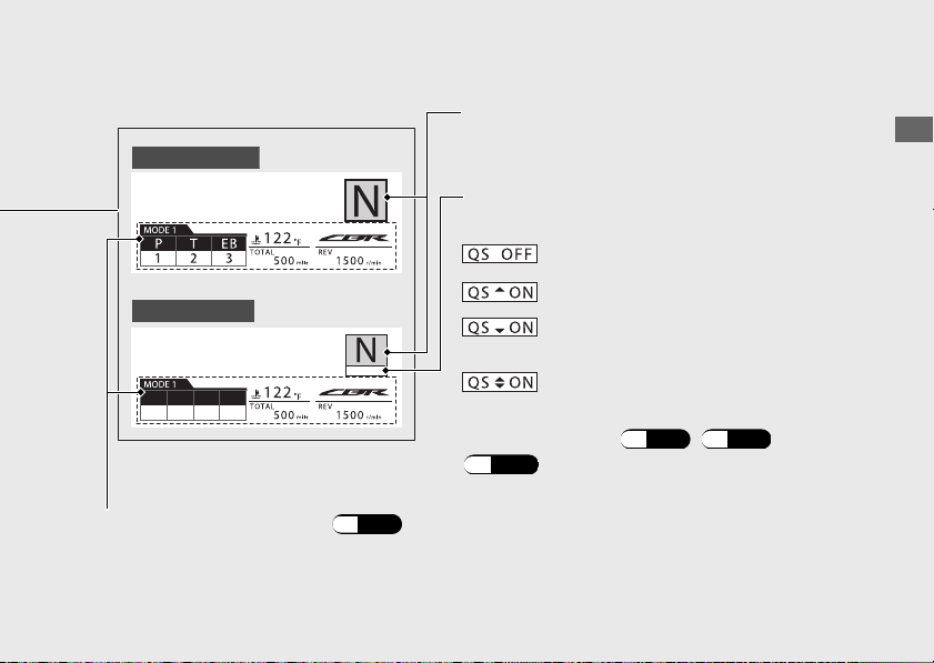
Multi-information display
(P.25)
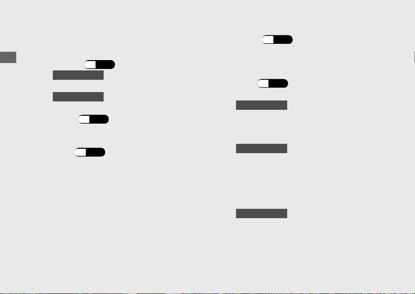
Quick Shifter indicator
Displays the current status of the Quick Shifter.
CBR1000RR/RA
CBR1000S1/S2
: Quick Shifter system is disabled.
: Quick Shifter upshifting is enabled.
: Quick Shifter downshifting is
enabled.
: Quick Shifter upshifting and
downshifting are both enabled.
QUICK SHIFTER:
(P.45) (P.46)
(P.110)
20170830152249_31MKF6100_enu_BOOK Page 27 Wednesday, August 30 2017 15:45:50 JST
Operation Guide
24
Instruments (Continued)
Display Check
When the ignition switch is turned to the ON position, the opening symbol will show on the
display. If the display itself does not shows when it should, have your dealer check for
problems.
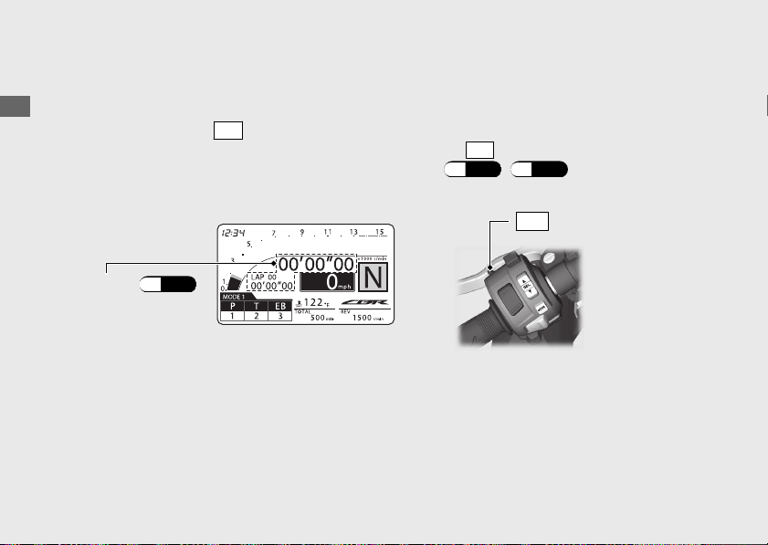
Circuit mode
To change to the circuit mode :
u To return to the street mode display, press and hold the
LAP
button.
● Press and hold the
LAP
button with your motorcycle stopped.
● Select the “CIRCUIT” menu on the “DISPLAY” screen.
(P.43) (P.59)
u To return to the street mode display, select the “STREET” menu on the “DISPLAY”
Lap timer
(P.86)
LAP
button
Multi-information display
20170830152249_31MKF6100_enu_BOOK Page 28 Wednesday, August 30 2017 15:45:50 JST
Operation Guide
25
Continued
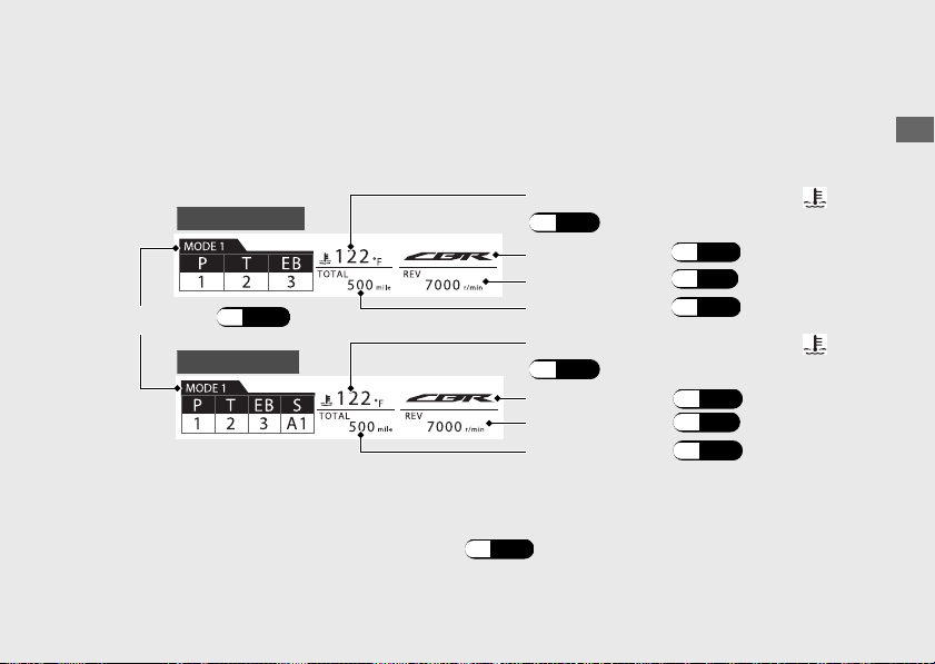
Multi-information display can display the coolant temperature gauge, riding modes, INFO 1,
INFO 2 and INFO 3 displays.
CBR1000RR/RA
CBR1000S1/S2
Riding mode
(P.101)
INFO 3 display (P.39)
INFO 2 display (P.31)
INFO 1 display (P.28)
You can change the riding modes, INFO 1
, INFO 2 and INFO 3 displays of the Multi-
information display.
To switch the multi-information display:
(P.27)
INFO 3 display (P.39)
INFO 2 display (P.31)
INFO 1 display (P.28)
Coolant temperature gauge ( )
(P.26)
Coolant temperature gauge ( )
(P.26)
Coolant temperature gauge ( )
Display range: 94°F (35°C) to 269°F (132°C)
● 93°F (34°C) or less: “---” is displayed.
● Between 251°F (122°C) and 268°F (131°C):
-
High coolant temperature indicator lights.
-
Coolant temperature digits flash.
● Above 269°F (132°C):
-
High coolant temperature indicator lights.
-
“269°F (132°C)” flashes.
● Even if the engine coolant temperature is low, the cooling fan may start running when you
rev up the engine. This is normal.
Pop-up information
In the following cases, the INFO 3 display, or the INFO 3 display and the coolant temperature
gauge change to a pop-up information display.
● When an inspection time of your motorcycle is approaching.
● When your motorcycle has helpful information.
● When your motorcycle has a problem with the PGM-FI system.
●
CBR1000S1/S2
When your motorcycle has a problem with the ÖHLINS Smart EC system.
Information of the pop-up information:
(P.90)
20170830152249_31MKF6100_enu_BOOK
Page 29 Wednesday, August 30 2017 15:45:50 JST
Operation Guide
26
Instruments (Continued)
20170830152249_31MKF6100_enu_BOOK Page 30 Wednesday, August 30 2017 15:45:50 JST
Operation Guide
27
Continued
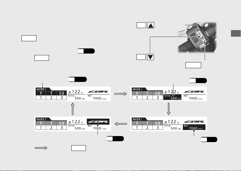
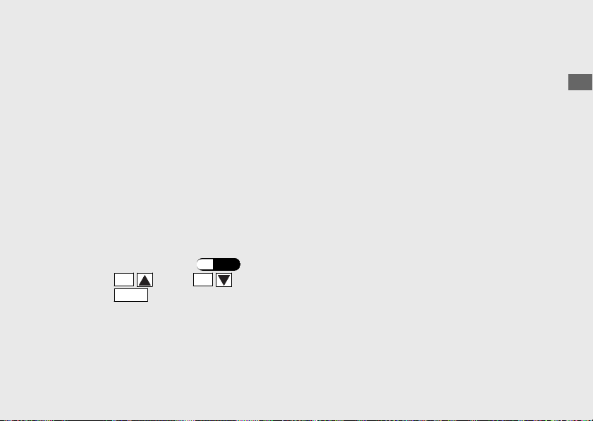
To switch the multi-information display
To select the display area, repeatedly press the
MODE
button.
Press the
MODE
button
SEL
(down) button
SEL
(up) button
MODE
button
Riding mode
(P.101)
INFO 1 display (P.28)
INFO 2 display (P.31)
INFO 3
display
(P.39)
If the
MODE
button is not pressed within 10
seconds, the display returns to the riding mode
display.
u Can not select the INFO 3 display while pop-up
information displayed.
(P.90)
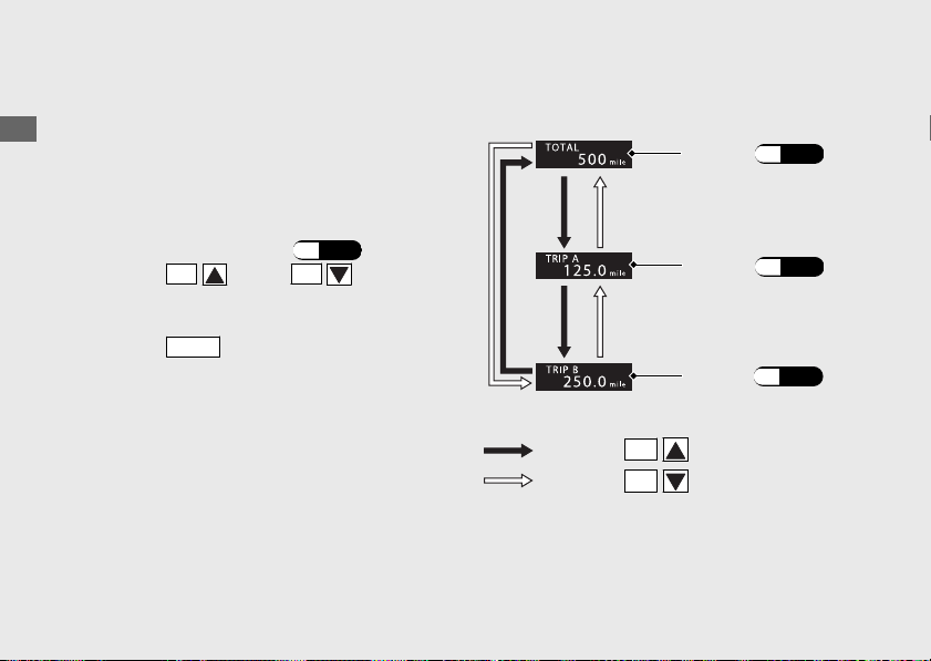
INFO
1
display
You can select the following:
• Odometer [TOTAL]
• Tripmeter [TRIP A/B]
Changing the INFO
1 display
a
Select the INFO 1 display.
(P.27)
b
Press the
SEL
(up) or
SEL
(down)
button until the desired indication is
displayed.
c
Press the
MODE
button. The INFO 1 display
is set, and then the display moves to the
INFO 2 display.
20170830152249_31MKF6100_enu_BOOK Page 31 Wednesday, August 30 2017 15:45:50 JST
Operation Guide
28
Instruments (Continued)
TOTAL
(P.29)
TRIP A
(P.29)
TRIP B
(P.29)
Press the
SEL
(down) button
Press the
SEL
(up) button
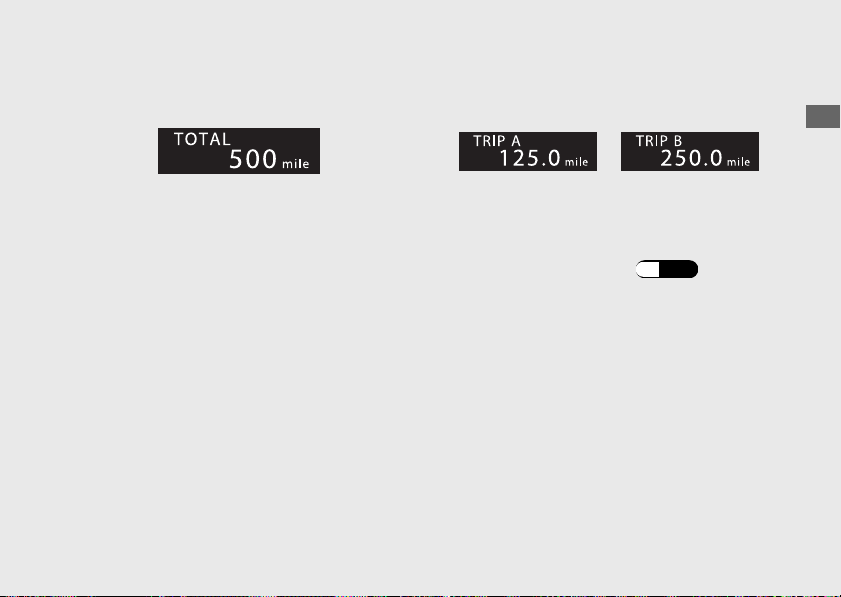
Odometer [TOTAL]
Total distance ridden.
When “------” is displayed, go to your dealer
for service.
Tripmeter A/B [TRIP A/B]
Distance ridden since the tripmeter was reset.
When “----.-” is displayed, go to your dealer
for service.
To reset the tripmeter: (P.30)
20170830152249_31MKF6100_enu_BOOK
Page 32 Wednesday, August 30 2017 15:45:50 JST
Operation Guide
29
Continued
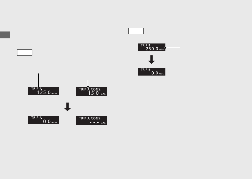
#
To Reset the Tripmeter and Tripmeter
A Fuel Consumption
To reset tripmeter A and tripmeter A fuel
consumption together, press and hold the
MODE
button with the tripmeter A or
tripmeter A fuel consumption displayed.
To reset the tripmeter B, press and hold the
MODE
button with the tripmeter B displayed.
20170830152249_31MKF6100_enu_BOOK Page 33 Wednesday, August 30 2017 15:45:50 JST
Operation Guide
30
Instruments (Continued)
Tripmeter A Tripmeter A fuel
consumption
or
or
Tripmeter B
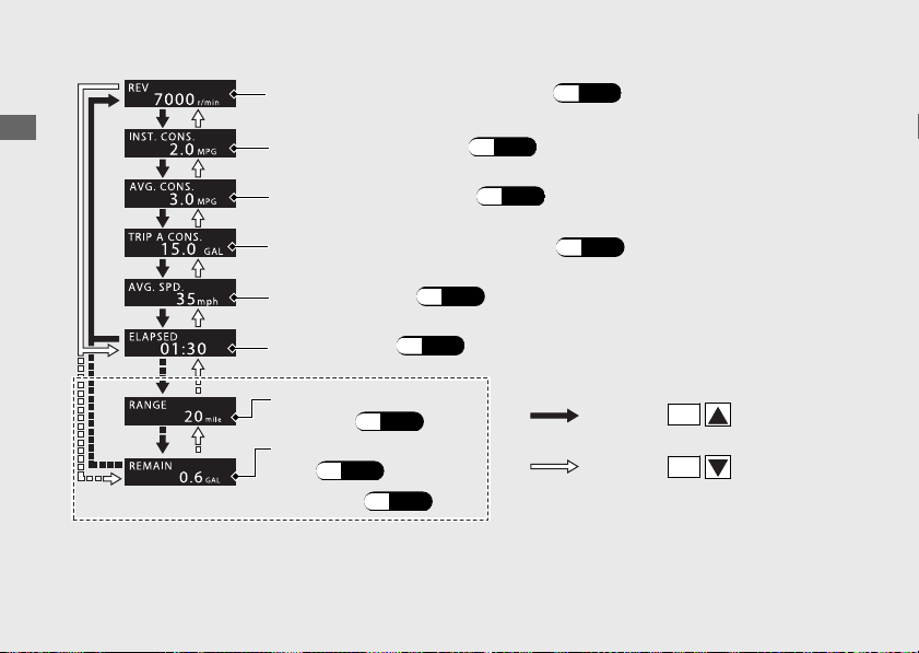
INFO
2
display
You can select the following:
• Numerical tachometer display [REV]
• Current fuel mileage [INST. CONS.]
• Average fuel mileage [AVE. CONS.]
• Tripmeter A fuel consumption [TRIP A CONS.]
• Average speed [AVG. SPD.]
• Elapsed time [ELAPSED]
• Available riding distance [RANGE]
• Amount of remaining fuel [REMAIN]
Changing the
INFO
2 display
a
Select the INFO 2 display.
(P.27)
b
Press the
SEL
(up) or
SEL
(down) button until the desired display is displayed.
c
Press the
MODE
button. The INFO 2 display is set, and display moves to the INFO 3 display.
20170830152249_31MKF6100_enu_BOOK Page 34 Wednesday, August 30 2017 15:45:50 JST
Operation Guide
31
Continued
When the low fuel indicator lights and the low fuel pop-up information appear, INFO 3 display
will automatically switches to the amount of remaining fuel display.
20170830152249_31MKF6100_enu_BOOK Page 35 Wednesday, August 30 2017 15:45:50 JST
Operation Guide
32
Instruments (Continued)
Numerical tachometer display
(P.33)
Current fuel mileage (P.33)
Average fuel mileage (P.34)
Tripmeter A fuel consumption (P.35)
Available riding
distance
(P.36)
Average speed (P.35)
Elapsed time (P.36)
Amount of remaining
fuel
(P.37)
Press the
SEL
(up)
button
Press the
SEL
(down)
button
Only when reserve fuel mode: (P.38)

Numerical tachometer Display [REV]
Displays engine revolutions per minutes.
Display range: 0 to 15,400 r/min (rpm)
● Above 15,400 r/min (rpm): “15400” is
displayed.
Current fuel mileage [INST. CONS.]
Displays the current instant fuel mileage.
Display range: 0.0 to 99.9 MPG (mile/L, L/
100km or km/L)
● When your speed is less than
4 mph (7
km/h): “--.-” is displayed.
● Above 99.9 MPG (mile/L or km/L):“99.9” is
displayed.
● Above 99.9 L/100km: “--.-” is displayed.
When “--.-” is displayed except for the
above-mentioned cases, go to your dealer
for service.
20170830152249_31MKF6100_enu_BOOK Page 36 Wednesday, August 30 2017 15:45:50 JST
Operation Guide
33
Continued
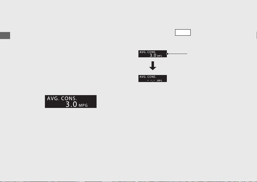
Average fuel mileage [AVG. CONS.]
Displays the average fuel mileage since the
average fuel mileage was reset.
Display range: 0.0 to 99.9 MPG
(mile/L, L/
100km or km/L)
● Above 99.9 MPG (mile/L or km/L): “99.9”
is displayed.
● Above 99.9 L/100km: “--.-” is displayed.
● When the average fuel mileage is reset:
“--.-” is displayed.
When “--.-” is displayed except for the
above-mentioned cases, go to your dealer
for service.
#
To Reset the Average Fuel Mileage
Press and hold the
MODE
button with the
average fuel mileage displayed.
20170830152249_31MKF6100_enu_BOOK Page 37 Wednesday, August 30 2017 15:45:50 JST
Operation Guide
34
Instruments (Continued)
Average fuel
mileage
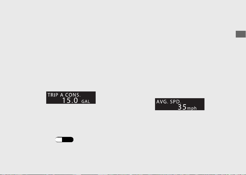
Tripmeter A fuel consumption [TRIP A
CONS.]
Displays the tripmeter A fuel consumption
since the tripmeter A was reset.
Display range: 0.0 to 300.0
GAL (gallon) or
0.0 to 300.0 L (liters)
● Above 300 GAL (gallon) or 300 L (liters):
“300.0” is displayed.
● When the tripmeter A fuel consumption is
reset: “---.-” is displayed.
When “---.-” is displayed except for the
above-mentioned cases, go to your dealer
for service.
To reset the tripmeter A fuel
consumption:
(P.30)
Average
speed [AVG. SPD.]
Displays average speed since the engine was
started.
Display range: 0 to 186 mph (0 to 299 km/h)
● Initial display: “
---” is displayed.
● When your motorcycle has traveled less
than 0.12 mile
(0.2 km) since the engine
was started: “---” is displayed.
● When your motorcycle operating time is
less than 16 seconds since the engine was
started: “---” is displayed.
When “---” is displayed except for the above-
mentioned cases, go to your dealer for
service.
20170830152249_31MKF6100_enu_BOOK Page 38 Wednesday, August 30 2017 15:45:50 JST
Operation Guide
35
Continued
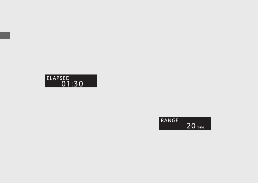
Elapsed time [ELAPSED]
Displays operating time since the engine was
started.
Display range: 00:00 to 99:59 (hours:minutes)
● Above 99:59: returns to 00:00.
When the ignition switch is turned to the OFF
position, the elapsed time is reset.
When “--:--” is displayed, go to your dealer
for service.
Available riding distance [RANGE] (Only
reserve fuel mode)
When the low fuel indicator lights and the
low fuel pop-up information appears, the
estimated available riding distance is
indicated.
Display range: 99 to 0 mile (km
)
● Above 99 mile (km): “99” is displayed.
● Below 0.2 GAL (1.0 L): “--” is displayed.
The indicated available riding distance is
calculated based on the riding states, and the
indicated figure may not always be the actual
allowable distance.
When “--” is displayed except for the above-
mentioned cases, go to your dealer for
service.
20170830152249_31MKF6100_enu_BOOK Page 39 Wednesday, August 30 2017 15:45:50 JST
Operation Guide
36
Instruments (Continued)

Amount of remaining fuel [REMAIN]
(Only reserve fuel mode)
When the low fuel indicator lights and the
low fuel pop-up information appears, the
estimated amount of remaining fuel can be
selected.
Display range: 0.9 to 0.2 GAL (gallon) or 4.0
to 1.0
L (liters)
● Below 0.2 GAL (1.0 L): “-.-” is displayed.
The amount of remaining fuel is calculated
based on the riding states.
The indicated amount of remaining fuel may
be different from the actual amount.
When “-.-” is displayed except for the above-
mentioned cases, go to your dealer for
service.
20170830152249_31MKF6100_enu_BOOK Page 40 Wednesday, August 30 2017 15:45:50 JST
Operation Guide
37
Continued

Reserve Fuel Mode
When the low fuel indicator lights and the
low fuel pop-up information appears, the
available riding distance is indicated, and the
amount of remaining fuel display can be
selected.
You should refill the tank as soon as possible.
Remaining fuel amount turned to the reserve
fuel mode:
1.1 US gal (4.0 L)
After refueling more than the reserve
amount, the display returns to normal when
the ignition switch has been ON position for
about a minute.
20170830152249_31MKF6100_enu_BOOK
Page 41 Wednesday, August 30 2017 15:45:50 JST
Operation Guide
38
Instruments (Continued)
Low fuel pop-up information
Available riding
distance
Low fuel indicator
INFO
3
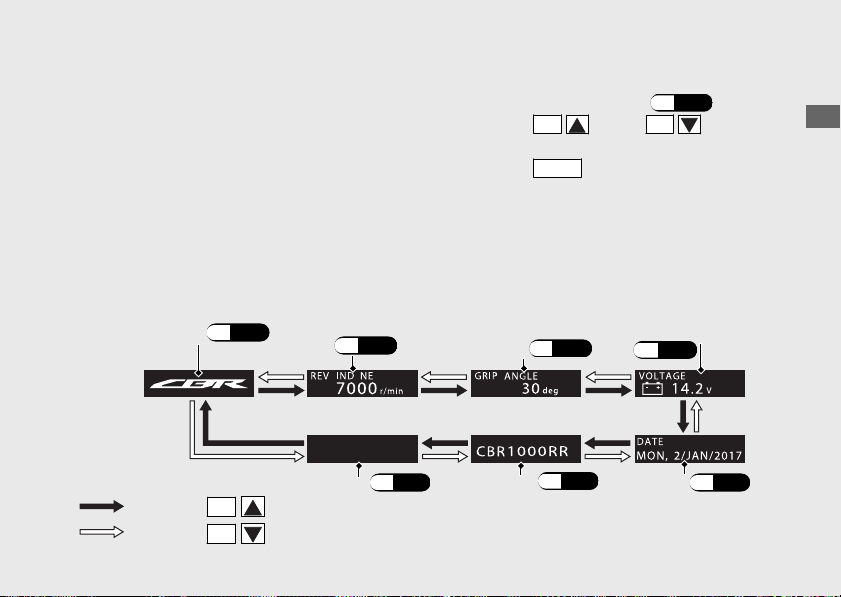
display
You can select the following:
• CBR Logo
• Shift indicator set value [REV IND NE]
• Throttle grip angle [GRIP ANGLE]
• Battery voltage [VOLTAGE]
• Date [DATE]
• User letter [USER LETTER]
• Blank display
Changing the INFO 3 display
a
Select the INFO 3 display.
(P.27)
b
Press the
SEL
(up) or
SEL
(down)
button until the desired display is displayed.
c
Press the
MODE
button. The INFO 3 display
is set, and then the display moves to the
riding mode display.
20170830152249_31MKF6100_enu_BOOK Page 42 Wednesday, August 30 2017 15:45:50 JST
Operation Guide
39
Continued
CBR Logo
(P.40)
Shift indicator set
value (P.40)
Throttle grip
angle
(P.40)
Blank display (P.41)
User letter (P.41)
Date (P.41)
Battery voltage
(P.
40)
Press the
SEL
(up) button
Press the
SEL
(down) button
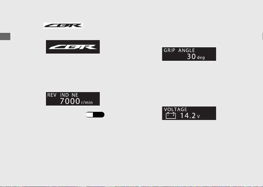
CBR logo
Displays the CBR logo.
Shift indicator set value [REV IND NE]
Displays the shift indicator set value.
Display range: OFF or 4,000 - 16,600
r/min
To set the shift indicator:
(P.61)
Throttle grip angle [GRIP ANGLE]
Displays the throttle grip angle during
operation.
When “--” is displayed, go to your dealer for
service.
Battery voltage [VOLTAGE]
Displays the current voltage.
20170830152249_31MKF6100_enu_BOOK
Page 43 Wednesday, August 30 2017 15:45:50 JST
Operation Guide
40
Instruments (Continued)
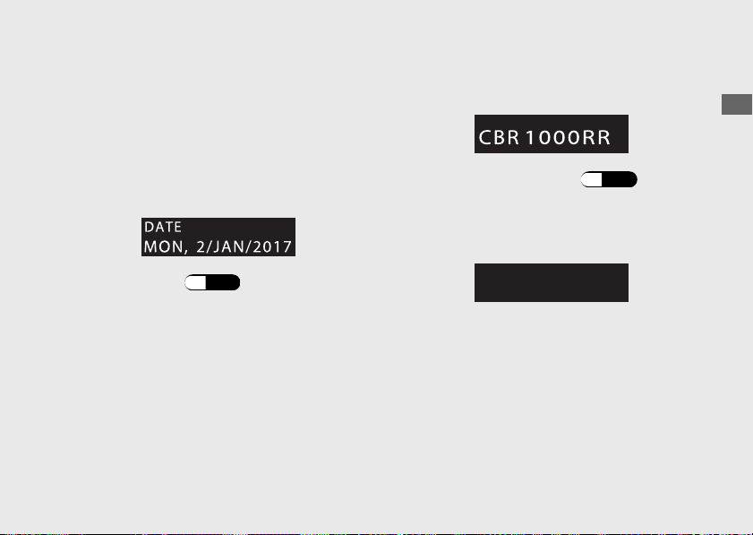
Date [DATE]
Displays the today's date.
Display range:
Day of the week: MON to SUN
DAY: 1 to 31
Month: JAN to DEC
Year: 2010
to 2099
To set the Date:
(P.70)
User letter
[USER LETTER]
Displays the characters of user's choice.
To set the USER LETTER:
(P.64)
Blank display
Display the blank.
20170830152249_31MKF6100_enu_BOOK
Page 44 Wednesday, August 30 2017 15:45:50 JST
Operation Guide
41
Continued
Setting mode
You can perform the following:
● FUNCTION
(P.45)
u
CBR1000S1/S2
Setting the Quick Shifter
u
CBR1000S1/S2
Setting the suspension
● LAP TIME
(P.55)
u Checking the lap time
u Resetting the lap time
● DISPLAY (P.58)
u Changing the display mode
u Setting the shift indicator
u Setting the backlight brightness
u Setting the back ground
u Setting the user letter
u Setting the favorite
● GENERAL (P.69)
u Setting the date and clock
u Setting each meter unit
u Resetting to factory default settings
● SERVICE (P.79)
u Checking the next inspection schedule
u
CBR1000S1/S2
SUSPENSION
“EQUIPMENT” is displayed but not
selectable.
u
CBR1000S1/S2
Quick Shifter
“INITIALIZE” and “EQUIPMENT” are
displayed but not selectable.
u Checking the current problem with the
PGM-FI system.
CBR1000S1/S2
Checking the current problem with the
ÖHLINS Smart EC system.
u “SPORTS KIT ECU USAGE” is displayed
but not usable.
● SPORTS KIT (Not selectable)
20170830152249_31MKF6100_enu_BOOK Page 45 Wednesday, August 30 2017 15:45:50 JST
Operation Guide
42
Instruments (Continued)
#
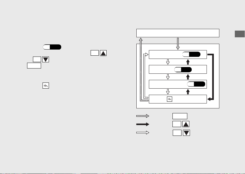
To Shift to the Setting Mode
Press and hold the
MODE
button and
SEL
(up) or
SEL
(down) button until main
menu screen is displayed with your
motorcycle stopped.
Select a menu by pressing the
SEL
(up)
or
SEL
(down) button and press the
MODE
button.
u Press and hold the
SEL
(up) or
SEL
(down) button to move the menu quickly.
20170830152249_31MKF6100_enu_BOOK Page 46 Wednesday, August 30 2017 15:45:50 JST
Operation Guide
43
Continued
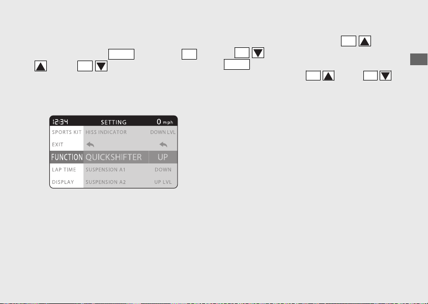
Main menu screen
To end the setting
Select the “EXIT
” menu on the main menu
screen, or press and hold the
MODE
button
and
SEL
(up) or
SEL
(down) button.
Also, the setting mode is ended when your
motorcycle speed reaches approximately 1
km/h (1 mph).
u Press and hold the
MODE
button and
SEL
(up) or
SEL
(down) button to return
to the ordinary display.
Note that doing so cancels the settings left
incomplete.
20170830152249_31MKF6100_enu_BOOK Page 47 Wednesday, August 30 2017 15:45:50 JST
Operation Guide
44
Instruments (Continued)
Ordinary display
FUNCTION
(P.45)
LAP TIME (P.55)
DISPLAY (P.58)
GENERAL (P.69)
SERVICE (P.79)
SPORTS KIT (Cannot select)
EXIT
Press the
MODE
button
Press and hold the
MODE
button
and
SEL
(up) or
SEL
(down)
button
Press the
SEL
(up) button
Press the
SEL
(down) button
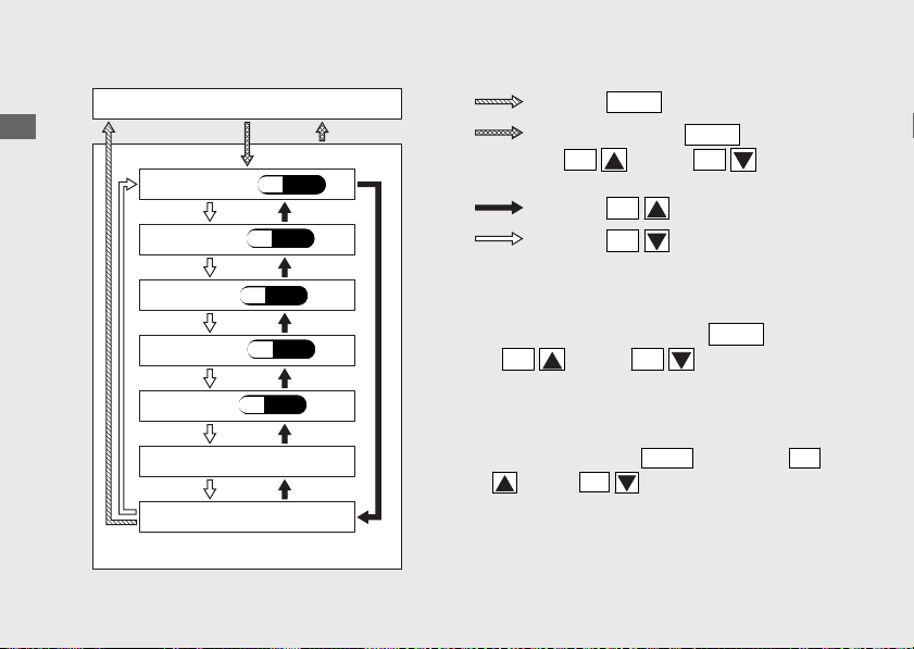
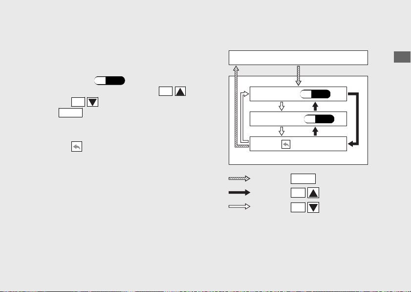
FUNCTION
#
To Set the FUNCTION Menu
a
Select the “FUNCTION” menu on the main
menu screen.
(P.43)
b
Select a menu by pressing the
SEL
(up)
or
SEL
(down) button and press the
MODE
button.
To end the setting
Select the
(return) on the menu screen.
The display returns to the “FUNCTION
” menu
on the main menu screen.
20170830152249_31MKF6100_enu_BOOK Page 48 Wednesday, August 30 2017 15:45:50 JST
Operation Guide
45
Continued
Press the
MODE
button
Press the
SEL
(up) button
Press the
SEL
(down) button
FUNCTION
QUICK SHIFTER
CBR1000S1/S2
(P.46)
SUSPENSION A1
CBR1000S1/S2
(P.51)
SUSPENSION A2
CBR1000S1/S2
(P.51)
SUSPENSION A3
CBR1000S1/S2
(P.51)
SUSPENSION M1
CBR1000S1/S2
(P.52)
SUSPENSION M2
CBR1000S1/S2
(P.52)
SUSPENSION M3
CBR1000S1/S2
(P.52)
(return)
"FUNCTION" is selected
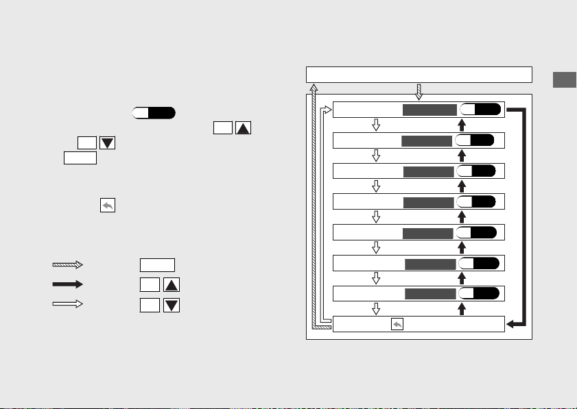
#
QUICK SHIFTER
CBR1000S1/S2
You can change the setting of the Quick
Shifter.
• UP:
To select “ON
” (activate) or “OFF”
(deactivate) for upshifting
(P.
47)
• DOWN:
To select “ON” (activate) or “OFF”
(deactivate) for downshifting (P.48)
• UP LVL:
To select the shift pedal load level for
activating the Quick Shifter when
upshifting (P.49)
• DOWN LVL:
To select the shift pedal load level for
activating the Quick Shifter when
downshifting (P.50)
To end the setting
Select the (return) on the menu screen.
The display returns to the “QUICKSHIFTER”
menu on the “FUNCTION
” screen.
To use the Quick Shifter
(P.110)
20170830152249_31MKF6100_enu_BOOK Page 49 Wednesday, August 30 2017 15:45:50 JST
Operation Guide
46
Instruments (Continued)
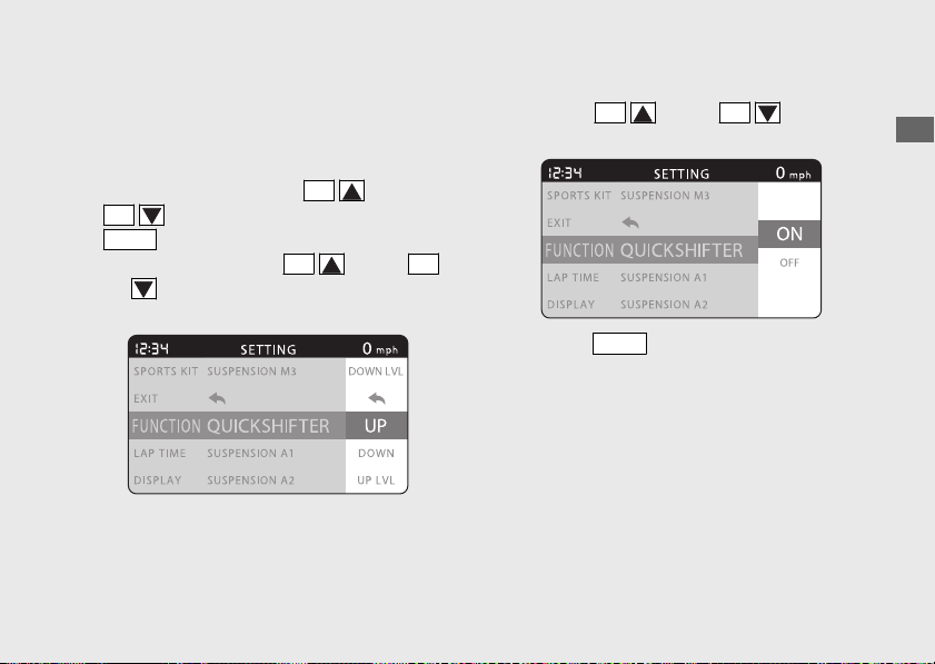
UP
You can select “ON” (activate) or “OFF”
(deactivate) for upshifting with the Quick
Shifter.
a
Select the “UP” using the
SEL
(up) or
SEL
(down) button, and press the
MODE
button.
u Press and hold the
SEL
(up) or
SEL
(down) button to move the menu
quickly.
b
Select “ON” (activate) or “OFF” (deactivate)
using the
SEL
(up) or
SEL
(down)
button.
c
Press the
MODE
button. The “UP” setting is
set, and then the display returns to the
upper level hierarchy.
20170830152249_31MKF6100_enu_BOOK Page 50 Wednesday, August 30 2017 15:45:50 JST
Operation Guide
47
Continued
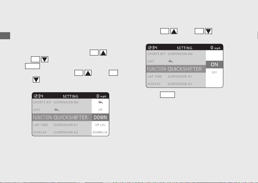
DOWN
You can select “ON” (activate) or “OFF”
(deactivate) for downshifting with the Quick
Shifter.
a
Select the “DOWN” using the
SEL
(up)
or
SEL
(down) button, and press the
MODE
button.
u Press and hold the
SEL
(up) or
SEL
(down) button to move the menu
quickly.
b
Select “ON” (activate) or “OFF” (deactivate)
using the
SEL
(up) or
SEL
(down)
button.
c
Press the
MODE
button. The “DOWN”
setting is set, and then the display returns to
the upper level hierarchy.
20170830152249_31MKF6100_enu_BOOK Page 51 Wednesday, August 30 2017 15:45:50 JST
Operation Guide
48
Instruments (Continued)
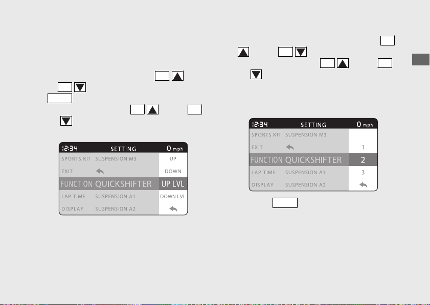
UP LVL
You can select the shift pedal load level for
activating the Quick Shifter when upshifting.
a
Select the “UP LVL” using the
SEL
(up)
or
SEL
(down) button, and press the
MODE
button.
u Press and hold the
SEL
(up) or
SEL
(down) button to move the menu
quickly.
b
Select one of the three levels using the
SEL
(up) or
SEL
(down) button.
u Press and hold the
SEL
(up) or
SEL
(down) button to move the menu
quickly.
u Available setting range:
1 (light operation) to 3
(heavy operation)
c
Press the
MODE
button. The “UP LVL”
setting is set, and then the display returns to
the upper level hierarchy.
20170830152249_31MKF6100_enu_BOOK Page 52 Wednesday, August 30 2017 15:45:50 JST
Operation Guide
49
Continued
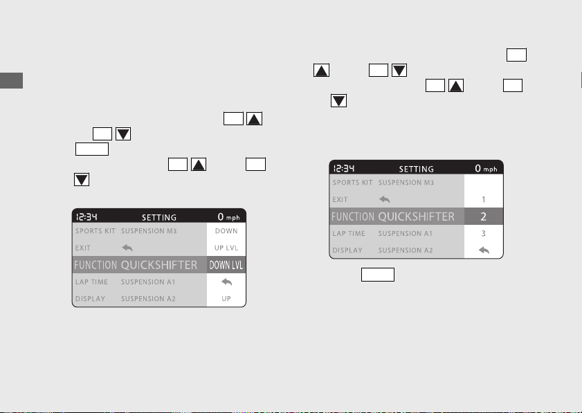
DOWN LVL
You can select the shift pedal load level for
activating the Quick Shifter when
downshifting.
a
Select the “DOWN LVL” using the
SEL
(up) or
SEL
(down) button, and press
the
MODE
button.
u Press and hold the
SEL
(up) or
SEL
(down) button to move the menu
quickly.
b
Select one of the three levels using the
SEL
(up) or
SEL
(down) button.
u Press and hold the
SEL
(up) or
SEL
(down) button to move the menu
quickly.
u Available setting range:
1 (light operation) to 3 (heavy operation)
c
Press the
MODE
button. The “DOWN LVL”
setting is set, and then the display returns to
the upper level hierarchy.
20170830152249_31MKF6100_enu_BOOK Page 53 Wednesday, August 30 2017 15:45:50 JST
Operation Guide
50
Instruments (Continued)
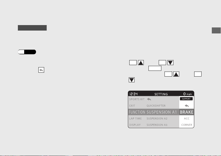
#
SUSPENSION A1, A2 and A3
CBR1000S1/S2
You can change the levels of OBTi support
items.
Adjusting the ÖHLINS Smart EC system
(P.170)
To end the setting
Select the (return) on the menu screen.
The display returns to the “SUSPENSION A1
”,
“SUSPENSION A2” or “SUSPENSION A3”
menu on the “FUNCTION” screen.
BRAKE, ACC (SUSPENSION A1 only),
CORNER (SUSPENSION A1 only) and
GENERAL
You can select the “DEFAULT” or one of the
ten suspension damping levels for damping
characteristics of the suspension.
a
Select the item you want to change using
the
SEL
(up) or
SEL
(down) button,
and press the
MODE
button.
u Press and hold the
SEL
(up) or
SEL
(down) button to move the menu
quickly.
20170830152249_31MKF6100_enu_BOOK Page 54 Wednesday, August 30 2017 15:45:50 JST
Operation Guide
51
Continued
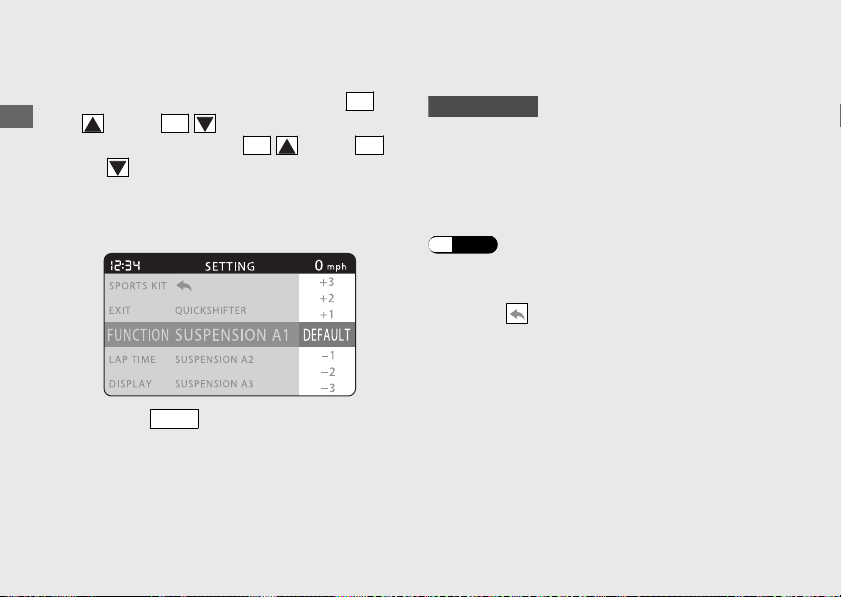
b
Select the “DEFAULT” or one of the ten
suspension damping levels using the
SEL
(up) or
SEL
(down) button.
u Press and hold the
SEL
(up) or
SEL
(down) button to move the menu
quickly.
u Available setting range:
-5 to +5
c
Press the
MODE
button. The selected item is
set, and then the display returns to the
upper level hierarchy.
#
SUSPENSION M1, M2 and M3
CBR1000S1/S2
You can adjust the compression and
rebound damping of the front and rear
suspension electronically.
Adjusting the ÖHLINS Smart EC system
(P.170)
To end the setting
Select the (return) on the menu screen.
The display returns to the “SUSPENSION M1”,
“SUSPENSION M2” or “SUSPENSION M3
”
menu on the “FUNCTION” screen.
20170830152249_31MKF6100_enu_BOOK Page 55 Wednesday, August 30 2017 15:45:50 JST
Operation Guide
52
Instruments (Continued)
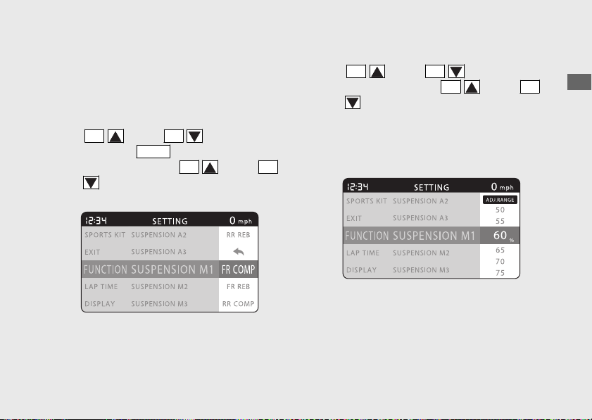
FR COMP, FR REB, RR COMP and RR REB
You can select one of the 21 different
damping levels for the front and rear
suspension.
a
Select the item you want to change using
the
SEL
(up) or
SEL
(down) button,
and press the
MODE
button.
u Press and hold the
SEL
(up) or
SEL
(down) button to move the menu
quickly.
b
Adjust to one of the 21 damping levels using
the
SEL
(up) or
SEL
(down) button.
u Press and hold the
SEL
(up) or
SEL
(down) button to move the menu
quickly.
u Available setting:
MIN (soft), MAX (hard), and the range
5% - 95% in 5% increments
20170830152249_31MKF6100_enu_BOOK
Page 56 Wednesday, August 30 2017 15:45:50 JST
Operation Guide
53
Continued
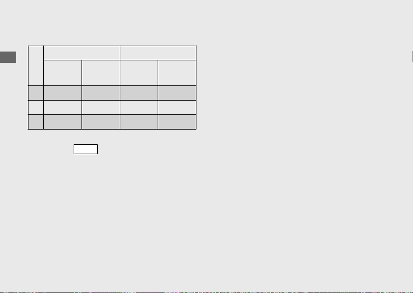
Preset settings are as follows.
Front Rear
Compression
FR COM
Rebound
FR REB
Compression
RR COM
Rebound
RR REB
M1 45% 30% 60% 50%
M2 20% 25% 50% 45%
M3 10% 10% 25% 30%
c
Press the
MODE
button. The selected the
item setting is set, and then the display
returns to the upper level hierarchy.
20170830152249_31MKF6100_enu_BOOK Page 57 Wednesday, August 30 2017 15:45:50 JST
Operation Guide
54
Instruments (Continued)
LAP
TIME
#
To Set the LAP TIME Menu
a
Select the “LAP TIME” menu on the main
menu screen.
(P.43)
b
Select the menu by pressing the
SEL
(up) or
SEL
(down) button, and press
the
MODE
button.
To end the setting
Select the
(return) on the menu screen.
The display returns to the “LAP TIME” menu
on the main menu screen.
20170830152249_31MKF6100_enu_BOOK
Page 58 Wednesday, August 30 2017 15:45:50 JST
Operation Guide
55
Continued
Press the
MODE
button
Press the
SEL
(up) button
Press the
SEL
(down) button
LAP TIME
LAP DATA
(P.56)
(return)
CLEAR DATA (P.57)
"LAP TIME" is selected

#
LAP DATA
The history of recorded lap time and
information are displayed.
To display the other lap information, press
the
SEL
(up) or
SEL
(down) button.
To display the maximum acceleration,
maximum deceleration, maximum left bank
angle and maximum right bank angle
information, press the
LAP
button.
To end the display of lap time history, press
the
MODE
button. The display returns to the
upper level hierarchy.
To use the Lap Timer
(P.86)
20170830152249_31MKF6100_enu_BOOK Page 59 Wednesday, August 30 2017 15:45:50 JST
Operation Guide
56
Instruments (Continued)
Best icon (Appears when the fastest lap time displayed.)
Lap number
Lap time
Time stamp
Press the
LAP
button
Maximum
vehicle speed
Maximum engine
revolutions
Maximum coolant temperature
Maximum left
bank angle
Maximum right
bank angle
Maximum acceleration
Maximum deceleration
DISPLAY
#
To Set the DISPLAY Menu
a
Select the “DISPLAY” menu on the main
menu screen.
(P.43)
b
Select the menu by pressing the
SEL
(up) or
SEL
(down) button and press the
MODE
button.
To end the setting
Select the
(return) on the menu screen.
The display returns to the “DISPLAY” menu
on the main menu screen.
20170830152249_31MKF6100_enu_BOOK
Page 61 Wednesday, August 30 2017 15:45:50 JST
Operation Guide
58
Instruments (Continued)
Press the
SEL
(down) button
Press the
SEL
(up) button
Press the
MODE
button
"DISPLAY" is selected
DISPLAY
DISPLAY MODE
(P.59)
BRIGHTNESS (P.62)
SHIFT INDICATOR (P.61)
BACKGROUND (P.63)
USER LETTER (P.64)
FAVORITE (P.65)
(return)
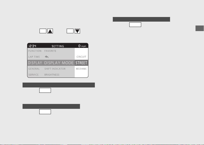
#
DISPLAY MODE
a
Select “STREET”, “MECHANIC” or “CIRCUIT”
using the
SEL
(up) or
SEL
(down)
button.
b
When the “STREET” or “CIRCUIT” is selected
Press the
MODE
button. The display mode
setting is set, and then the display returns to
the upper level hierarchy.
When the “MECHANIC” is selected
Press the
MODE
button. The display moves
to the mechanic mode.
c
When the “MECHANIC” is selected
Press the
MODE
button. The mechanic
mode ends, and then the display returns to
the upper level hierarchy.
u The display mode returns to the
previously selected mode.
20170830152249_31MKF6100_enu_BOOK Page 62 Wednesday, August 30 2017 15:45:50 JST
Operation Guide
59
Continued
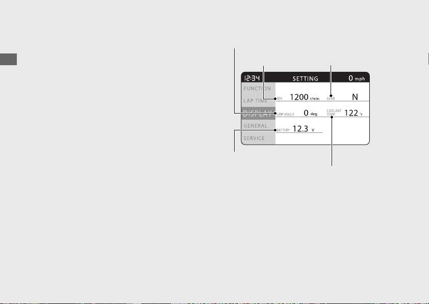
Mechanic Mode
Displays the current information of the
motorcycle.
Displays the following information:
● Tachometer
● Gear position
● Throttle grip position
● Coolant temperature
● Battery voltage
20170830152249_31MKF6100_enu_BOOK Page 63 Wednesday, August 30 2017 15:45:50 JST
Operation Guide
60
Instruments (Continued)
Throttle grip position
Tachometer Gear position
Battery voltage
Coolant temperature
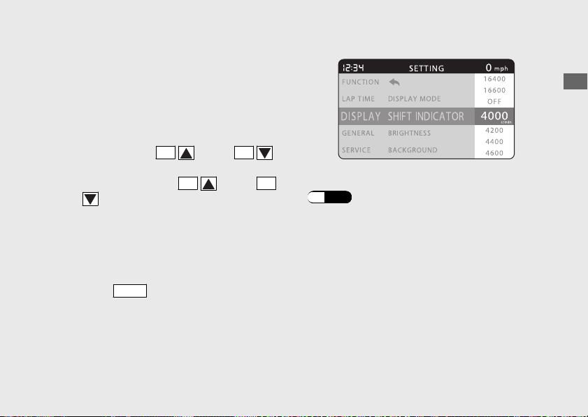
#
SHIFT INDICATOR
You can change the setting of the shift
indicators.
a
Select the “OFF” (deactivate) or an engine
revolution at which the shift indicators start
blinking using the
SEL
(up) or
SEL
(down) button.
u Press and hold the
SEL
(up) or
SEL
(down) button to move the menu
quickly.
u The value increases by 200 r/min (rpm)
increments.
u Available setting range:
4,000 - 16,600 r/min (rpm)
b
Press the
MODE
button. The shift indicator
setting is set, and then the display returns to
the upper level hierarchy.
Information of the Shift Indicator:
(P.96)
20170830152249_31MKF6100_enu_BOOK
Page 64 Wednesday, August 30 2017 15:45:50 JST
Operation Guide
61
Continued
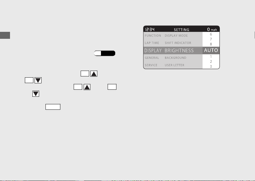
#
BRIGHTNESS
You can adjust the backlight brightness to
one of the eight levels or select the auto
adjustment.
Automatic brightness control
(P.203)
a
Select the “AUTO” (auto adjustment) or
brightness level using the
SEL
(up) or
SEL
(down) button.
u Press and hold the
SEL
(up) or
SEL
(down) button to move the menu
quickly.
b
Press the
MODE
button. The backlight
brightness setting is set, and then the display
returns to the upper level hierarchy.
20170830152249_31MKF6100_enu_BOOK Page 65 Wednesday, August 30 2017 15:45:50 JST
Operation Guide
62
Instruments (Continued)
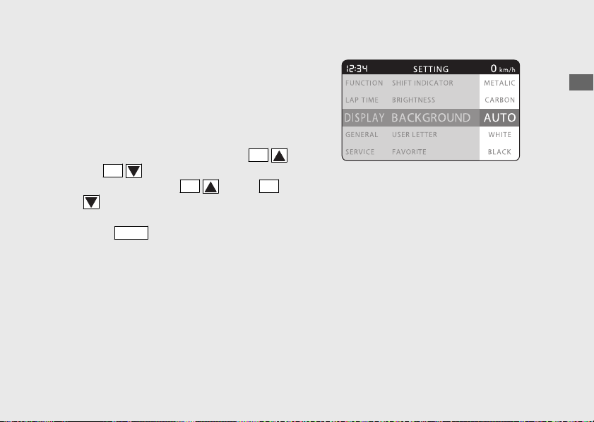
#
BACKGROUND
You can change the setting of the
background to one of the four categories or
select the auto adjustment.
a
Select the “AUTO”, “WHITE”, “BLACK”,
“METALLIC” or “CARBON” using the
SEL
(up) or
SEL
(down) button.
u Press and hold the
SEL
(up) or
SEL
(down) button to move the menu
quickly.
b
Press the
MODE
button. The background
setting is set, and then the display returns to
the upper level hierarchy.
20170830152249_31MKF6100_enu_BOOK Page 66 Wednesday, August 30 2017 15:45:50 JST
Operation Guide
63
Continued

#
USER LETTER
You can select any 10 characters you like.
a
Select the first character using the
SEL
(up) or
SEL
(down) button until a
desired character appears.
u Press and hold the
SEL
(up) or
SEL
(down) button to move the menu
quickly.
b
Press the
MODE
button. The cursor moves
to the next position.
c
Repeat the steps a and b to select
characters for the other positions until a
desired word is complete.
d
When the tenth character is selected, the
display returns to the upper level hierarchy.
A list of characters
that can be selected
A B C D E F G H I
J K L M N O P Q R
S T U V W X Y Z 0
1 2 3 4 5 6 7 8 9
! ” # $ % & ‘ ’ (
) * + , - . / : ;
< > = ? @ ^ _
20170830152249_31MKF6100_enu_BOOK Page 67 Wednesday, August 30 2017 15:45:50 JST
Operation Guide
64
Instruments (Continued)

#
FAVORITE
You can change the indications on the INFO
1, INFO 2, and INFO 3 to the following
information by pressing the
LAP
button while
the street mode is displayed.
INFO 1:
“TOTAL”, “TRIP A” or “TRIP B”
INFO 2:
“REV”, “INST.CONS.”, “AVG.CONS.”, “TRIP A
CONS.”, “AVG.SPD.” or “ELAPSED”
INFO 3:
“CBR LOGO”, “REV IND NE”, “GRIP ANGLE”,
“VOLTAGE”, “DATE”, “USER LETTER” or blank
display
To end the setting
Select the
(return) on the menu screen.
The display returns to the “FAVORITE” menu
on the “DISPLAY
” menu screen.
20170830152249_31MKF6100_enu_BOOK Page 68 Wednesday, August 30 2017 15:45:50 JST
Operation Guide
65
Continued
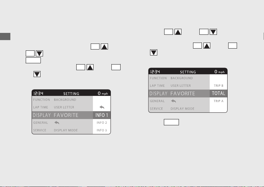
INFO 1
You can select the “TOTAL”, “TRIP A” or “
TRIP
B” for INFO 1.
a
Select the “INFO 1” using the
SEL
(up) or
SEL
(down) button, and press the
MODE
button.
u Press and hold the
SEL
(up) or
SEL
(down) button to move the menu
quickly.
b
Select the “TOTAL”, “TRIP A” or “TRIP B”
using the
SEL
(up) or
SEL
(down)
button.
u Press and hold the
SEL
(up) or
SEL
(down) button to move the menu
quickly.
c
Press the
MODE
button. The “INFO 1”
setting is set, and then the display returns to
the upper level hierarchy.
20170830152249_31MKF6100_enu_BOOK Page 69 Wednesday, August 30 2017 15:45:50 JST
Operation Guide
66
Instruments (Continued)
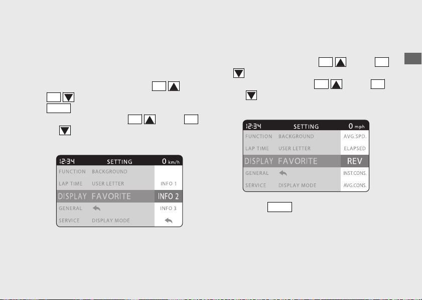
INFO 2
You can select the “REV”, “INST.CONS.”,
“AVG.CONS.
”, “TRIP A CONS.”, “AVG.SPD.” or
“ELAPSED” for INFO 2.
a
Select the “INFO 2” using the
SEL
(up) or
SEL
(down) button, and press the
MODE
button.
u Press and hold the
SEL
(up) or
SEL
(down) button to move the menu
quickly.
b
Select the “REV”, “INST.CONS.”,
“AVG.CONS.”, “TRIP A CONS.”, “AVG.SPD.”
or “ELAPSED
” using the
SEL
(up) or
SEL
(down) button.
u Press and hold the
SEL
(up) or
SEL
(down) button to move the menu
quickly.
c
Press the
MODE
button. The “INFO 2”
setting is set, and then the display returns to
the upper level hierarchy.
20170830152249_31MKF6100_enu_BOOK Page 70 Wednesday, August 30 2017 15:45:50 JST
Operation Guide
67
Continued
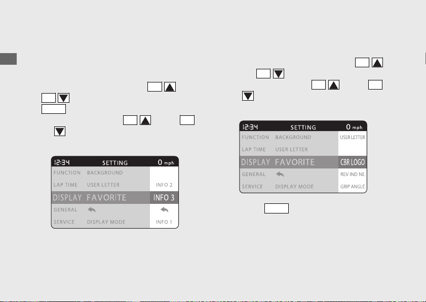
INFO 3
You can select the “CBR LOGO”, “REV IND
NE”, “GRIP ANGLE”, “VOLTAGE”, “DATE”,
“USER LETTER” or blank display for INFO 3
.
a
Select the “INFO 3” using the
SEL
(up) or
SEL
(down) button, and press the
MODE
button.
u Press and hold the
SEL
(up) or
SEL
(down) button to move the menu
quickly.
b
Select the “CBR LOGO”, “REV IND NE”, “GRIP
ANGLE”, “VOLTAGE”, “DATE”, “USER
LETTER” or blank display using the
SEL
(up) or
SEL
(down) button.
u Press and hold the
SEL
(up) or
SEL
(down) button to move the menu
quickly.
c
Press the
MODE
button. The “INFO 3”
setting is set, and then the display returns to
the upper level hierarchy.
20170830152249_31MKF6100_enu_BOOK Page 71 Wednesday, August 30 2017 15:45:50 JST
Operation Guide
68
Instruments (Continued)
GENERAL
#
To Set the GENERAL Menu
a
Select the “GENERAL” on the main menu
screen.
(P.43)
b
Select a menu by pressing the
SEL
(up)
or
SEL
(down) button and press the
MODE
button.
To end the setting
Select the
(return) menu on the menu
screen. The display returns to the “GENERAL”
on the main menu screen.
20170830152249_31MKF6100_enu_BOOK
Page 72 Wednesday, August 30 2017 15:45:50 JST
Operation Guide
69
Continued
"GENERAL" is selected
GENERAL
DATE & TIME
(P.70)
UNITS (P.71)
RESTORE DEFAULT (P.76)
(return)
Press the
MODE
button
Press the
SEL
(up) button
Press the
SEL
(up) button
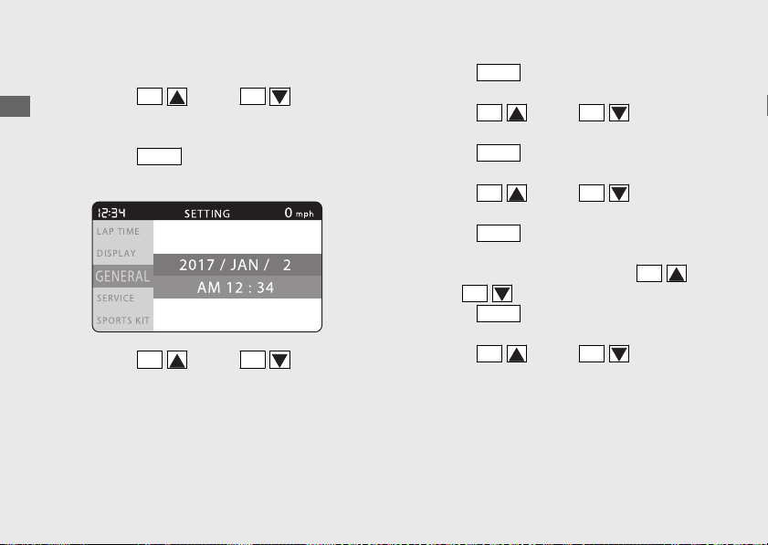
#
DATE & TIME
a
Press the
SEL
(up) or
SEL
(down)
button until the desired tens digit of the year
is displayed.
b
Press the
MODE
button. The cursor moves
to the ones digit of the year.
c
Press the
SEL
(up) or
SEL
(down)
button until the desired ones digit of the
year is displayed.
d
Press the
MODE
button. The cursor moves
to the indication of month.
e
Press the
SEL
(up) or
SEL
(down)
button until the desired month is displayed.
f
Press the
MODE
button. The cursor moves
to the indication of date.
g
Press the
SEL
(up) or
SEL
(down)
button until the desired date is displayed.
h
Press the
MODE
button. The cursor moves
to the “AM” or “PM”.
i
Select the “AM” or “PM” using the
SEL
(up) or
SEL
(down) button.
j
Press the
MODE
button. The cursor moves
to the indication of hour.
k
Press the
SEL
(up) or
SEL
(down)
button until the desired hour is displayed.
20170830152249_31MKF6100_enu_BOOK Page 73 Wednesday, August 30 2017 15:45:50 JST
Operation Guide
70
Instruments (Continued)
l
Press the
MODE
button. The cursor moves
to the indication of minute.
m
Press the
SEL
(up) or
SEL
(down)
button until the desired minute is displayed.
n
Press the
MODE
button. The date and clock
setting is set, and then the display returns to
the upper level hierarchy.
Press and hold the
SEL
(up) or
SEL
(down) button to move the menu quickly.
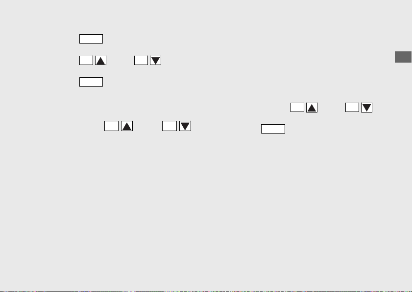
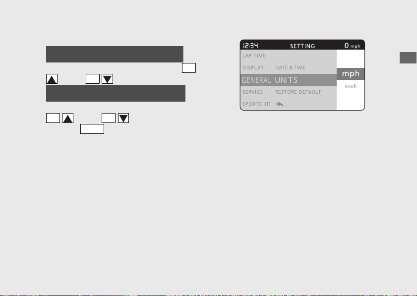
#
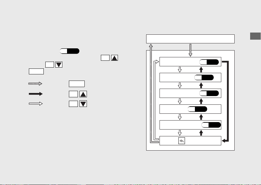
UNITS
You can change the speed and mileage,
temperature, and fuel mileage meter units.
To set each unit
a
Select the “SPEED”, “TEMP.” or “FUEL
CONS.” using the
SEL
(up) or
SEL
(down) button.
b
Press the
MODE
button. The display moves
to each unit setting screen.
The units of the speedometer, odometer,
tripmeter A/B, current fuel mileage, average
fuel mileage, tripmeter A fuel consumption,
average speed, available riding distance and
amount of remaining fuel are changed in
“SPEED” menu.
20170830152249_31MKF6100_enu_BOOK Page 74 Wednesday, August 30 2017 15:45:50 JST
Operation Guide
71
Continued
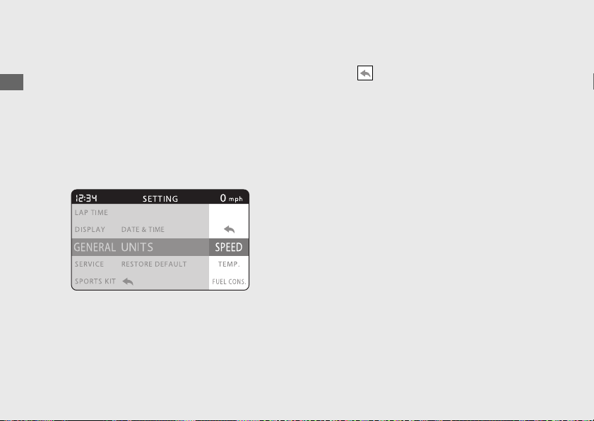
The unit of coolant temperature gauge and
information of temperature (lap data history
mode and mechanic mode) is changed by
“TEMP.” menu.
The units of the current fuel mileage, average
fuel mileage and amount of remaining fuel
are changed in “FUEL CONS.” menu.
To end the setting
Select the (return) on the menu screen.
The display returns to the “UNITS” menu on
the “GENERAL” menu screen.
20170830152249_31MKF6100_enu_BOOK
Page 75 Wednesday, August 30 2017 15:45:50 JST
Operation Guide
72
Instruments (Continued)
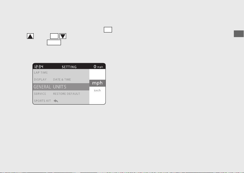
Speed and mileage unit [SPEED]
a
Select the “mph” or “km/h” using the
SEL
(up) or
SEL
(down) button.
b
Press the
MODE
button. The speed and
mileage unit setting is set, and then the
display returns to the upper level hierarchy.
When selecting the “mph”
● Units of the speedometer and average
speed show “mph”.
● Units of the odometer, tripmeter A/B and
available riding distance show “mile”.
● Units of the current fuel mileage and
average fuel mileage show “MPG” or
“mile/L”.
● Units of the tripmeter
A fuel consumption
and amount of remaining fuel show “GAL”
or “L”.
20170830152249_31MKF6100_enu_BOOK Page 76 Wednesday, August 30 2017 15:45:50 JST
Operation Guide
73
Continued
When selecting the “km/h”
● Units of the speedometer and average
speed show “km/h”.
● Units of the odometer, tripmeter A/B and
available riding distance show “km
”.
● Units of the current fuel mileage and
average fuel mileage show “L/100km” or
“km/L”.
● Units of the tripmeter A fuel consumption
and amount of remaining fuel show “L”.
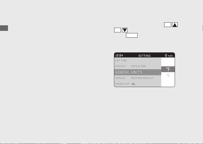
Temperature
unit [TEMP.]
a
Select the “°F” or “°C” using the
SEL
(up)
or
SEL
(down) button.
b
Press the
MODE
button. The temperature
unit setting is set, and then the display
returns to the upper level hierarchy.
20170830152249_31MKF6100_enu_BOOK Page 77 Wednesday, August 30 2017 15:45:50 JST
Operation Guide
74
Instruments (Continued)
Fuel mileage meter unit [FUEL CONS.]
a
When the “mph” of the “SPEED” menu is
selected
Select the “MPG” or “mile/L” using the
SEL
(up) or
SEL
(down) button.
When the “km/h” of the “SPEED” menu is
selected
Select the “L/100 km” or “km/L” using the
SEL
(up) or
SEL
(down) button.
b
Press the
MODE
button. The fuel mileage
meter unit setting is set, and then the display
returns to the upper level hierarchy.
When selecting the “MPG”
● Units of the current fuel mileage and
average fuel mileage show “MPG”.
● Units of the tripmeter A fuel consumption
and amount of remaining fuel show
“GAL”.
When selecting the “mile/L”
● Units of the current fuel mileage and
average fuel mileage show “mile/L”.
● Units of the tripmeter A fuel consumption
and amount of remaining fuel show “L”.
20170830152249_31MKF6100_enu_BOOK
Page 78 Wednesday, August 30 2017 15:45:50 JST
Operation Guide
75
Continued
When selecting the “L/100 km”
● Units of the current fuel mileage and
average fuel mileage show “L/100 km”.
● Units of the tripmeter A fuel consumption
and amount of remaining fuel show “L”.
When selecting the “km/L”
● Units of the current fuel mileage and
average fuel mileage show “km/L”.
● Units of the tripmeter A fuel consumption
and amount of remaining fuel show “L”.
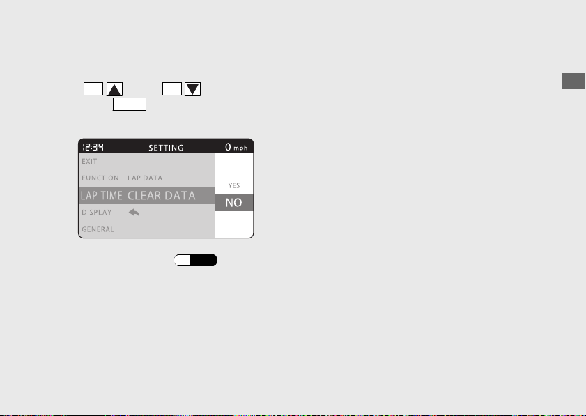
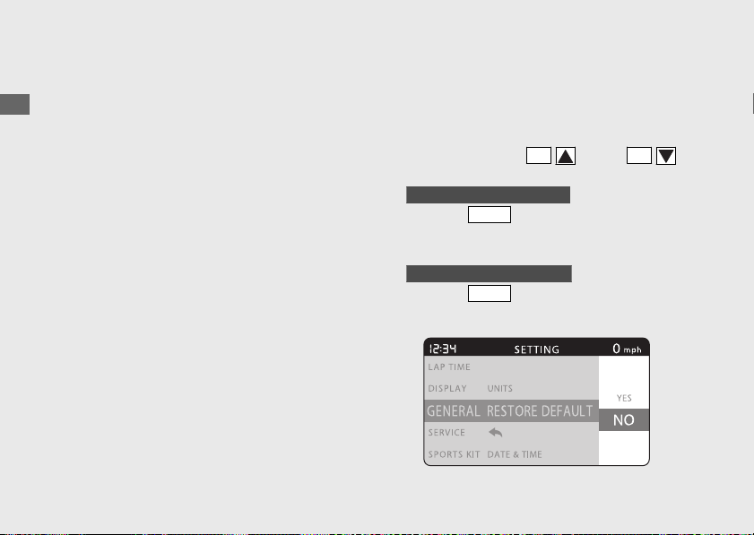
#
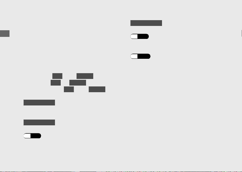
RESTORE DEFAULT
The set value can be returned to default
setting.
a
Select the “NO” (not restore) or “YES”
(restore) using the
SEL
(up) or
SEL
(down) button.
b
When the “NO” is selected
Press the
MODE
button. The set value is
maintained, and then the display returns to
the upper level hierarchy.
When the “YES” is selected
Press the
MODE
button. The display
changes to the confirmation screen.
20170830152249_31MKF6100_enu_BOOK Page 79 Wednesday, August 30 2017 15:45:50 JST
Operation Guide
76
Instruments (Continued)
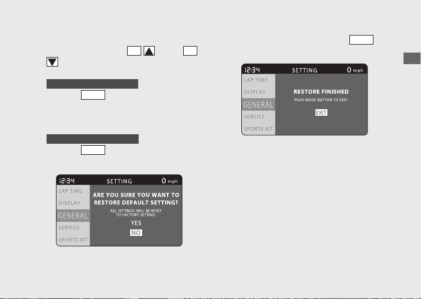
c
Select the “NO” (not restore) or “YES”
(restore) using the the
SEL
(up) or
SEL
(down) button on the confirmation
screen.
d
When the “NO” is selected
Press the
MODE
button. The set value is
maintained, and then the display returns to
the “RESTORE DEFAULT” menu on the
“GENERAL” menu screen.
When the “YES” is selected
Press the
MODE
button. The set value
return to default setting.
e
Select the “EXIT” by pressing the
MODE
button.
f
The display returns to the “RESTORE
DEFAULT” menu on the “GENERAL” menu
screen.
20170830152249_31MKF6100_enu_BOOK Page 80 Wednesday, August 30 2017 15:45:50 JST
Operation Guide
77
Continued
Default setting values:
● LAP DATA: Cleared
● DISPLAY MODE: STREET
● SHIFT INDICATOR: OFF
● BRIGHTNESS: AUTO
● BACK GROUND: AUTO
● USER LETTER: CBR1000RR
● FAVORITE: TOTAL, REV, CBR LOGO
● SPEED UNIT:
USA
mph (
Canada
km/h)
● TEMP UNIT:
USA
°F (
Canada
°C)
● FUEL CONS UNIT:
USA
MPG (
Canada
L/
100km)
●
CBR1000S1/S2
QUICK SHIFTER: OFF (Quick Shifter
system is disabled.)
●
CBR1000S1/S2
SUSPENSION A1, A2, A3: Default setting
(P.51)
●
CBR1000S1/S2
SUSPENSION M1, M2, M3: Preset setting
(P.54)
● Riding mode:
USER 1 and USER 2 setting
value returns to initial setting values.
(P.102)
20170830152249_31MKF6100_enu_BOOK Page 81 Wednesday, August 30 2017 15:45:50 JST
Operation Guide
78
Instruments (Continued)
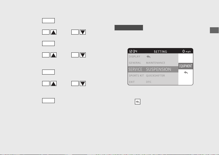
SERVICE
#
To Set the SERVICE Menu
a
Select the “SERVICE” menu on the main
menu screen.
(P.43)
b
Select the menu by pressing the
SEL
(up) or
SEL
(down) button and press the
MODE
button.
20170830152249_31MKF6100_enu_BOOK Page 82 Wednesday, August 30 2017 15:45:50 JST
Operation Guide
79
Continued
Press the
MODE
button
Press the
SEL
(up) button
Press the
SEL
(down) button
MAINTENANCE
(P.80)
SUSPENSION
(P.83)
QUICK SHIFTER (P.84)
DTC (P.84)
SPORTS KIT ECU (P.85)
(return)
SERVICE
"SERVICE" is selected
To end the setting
Select the (return) on the menu screen,
and then the display returns to the “SERVICE”
menu on the main menu screen.
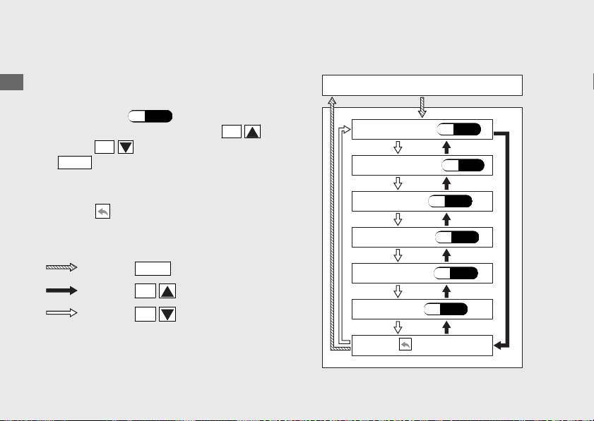
#
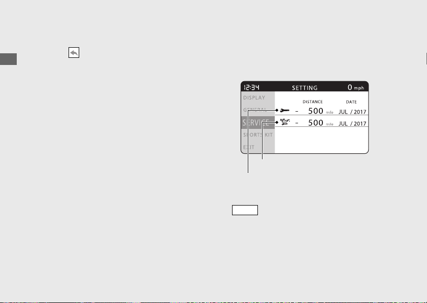
MAINTENANCE
You can check the next inspection time and
change the setting of next inspection.
To return to the upper level hierarchy, press
the
MODE
button.
20170830152249_31MKF6100_enu_BOOK Page 83 Wednesday, August 30 2017 15:45:50 JST
Operation Guide
80
Instruments (Continued)
Next engine oil change
Next periodic inspection
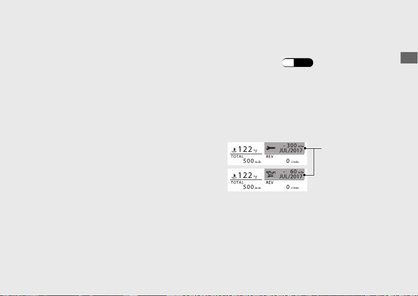
Display range:
DISTANCE:
Next periodic inspection:
-8000 to +99950 mile
(-12000 to +99900 km)
Next engine oil change:
-4000 to +99980 mile
(-6000 to +99980 km)
u Pass 0 mile (km): “-” mark changed to
“+
” mark
DATE:
Month:
JAN to DEC
Year: 2010 to 2099
When reaching any of the following, the
pop-up information is appears in the
ordinary display.
(P.90)
● “-300 mile” or “-500 km” from the next
periodic inspection
● “-60 mile” or “-100 km” from the next
engine oil change
● One month before the set month
20170830152249_31MKF6100_enu_BOOK
Page 84 Wednesday, August 30 2017 15:45:50 JST
Operation Guide
81
Continued
Maintenance
pop-up
information
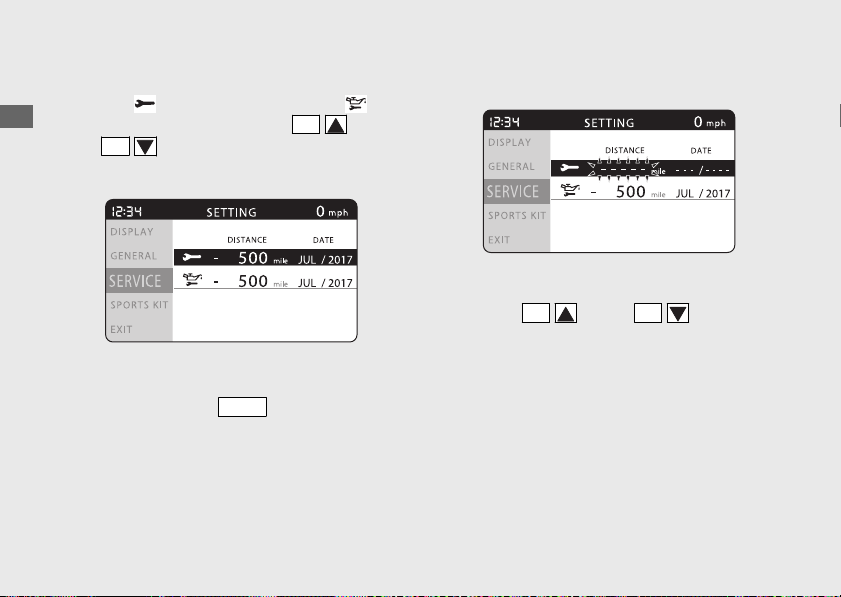
Next inspection setting
a
Select “ ” (periodic inspection ) or “ ”
(engine oil change) using the
SEL
(up)
or
SEL
(down) button.
b
Press and hold the
MODE
button until the
“DISTANCE” value start flashing.
c
Press the
SEL
(up) or
SEL
(down)
button until the desired distance value is
displayed.
u Available setting range of periodic
inspection:
100 to 4,000 mile
(100 to 6,400 km)
u Available setting range of engine oil
change:
100 to 8,000 mile (100 to 12,800 km)
20170830152249_31MKF6100_enu_BOOK Page 85 Wednesday, August 30 2017 15:45:50 JST
Operation Guide
82
Instruments (Continued)
d
Press the
MODE
button. The cursor moves
to the indication of month.
e
Press the
SEL
(up) or
SEL
(down)
button until the desired month is displayed.
f
Press the
MODE
button. The cursor moves
to the tens digit of the year.
g
Press the
SEL
(up) or
SEL
(down)
button until the desired tens digit of the year
is displayed.
h
Press the
MODE
button. The cursor moves
to the ones digit of the year.
i
Press the
SEL
(up) or
SEL
(down)
button until the desired ones digit of the
year is displayed.
j
Press the
MODE
button. The mileage and
date setting is set, and then the display
returns to the upper level hierarchy.
#
SUSPENSION
CBR1000S1/S2
“EQUIPMENT” is displayed but not selectable.
Select the
(return) on the menu screen.
The display returns to the “SUSPENSION”
menu on the “
SERVICE” menu screen.
20170830152249_31MKF6100_enu_BOOK Page 86 Wednesday, August 30 2017 15:45:50 JST
Operation Guide
83
Continued
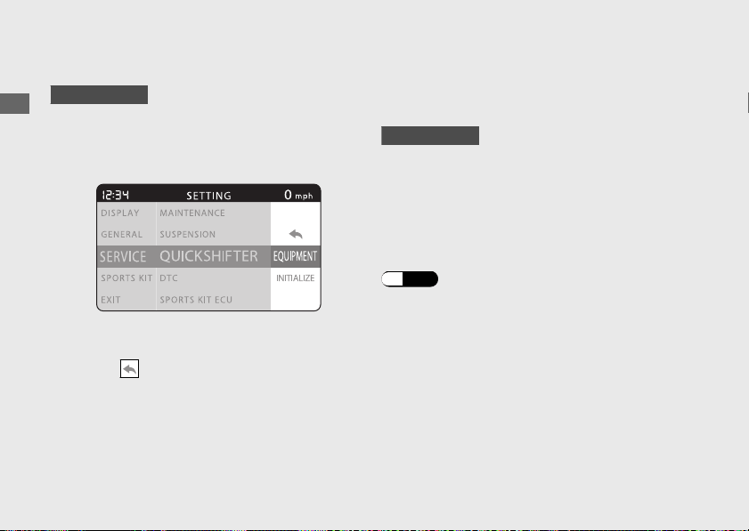
#
QUICK SHIFTER
CBR1000S1/S2
“INITIALIZE” and “EQUIPMENT” are displayed
but not selectable.
Select the
(return) on the menu screen,
and then the display returns to the
“QUICKSHIFTER” menu on the “SERVICE
”
menu screen.
#
DTC
You can check for a current problem with the
PGM-FI system.
CBR1000S1/S2
You can check for a current problem with the
ÖHLINS Smart EC system.
If your motorcycle has a problem, the DTC
index is displayed. In this case, the pop-up
information appears in the ordinary display.
(P.90)
20170830152249_31MKF6100_enu_BOOK
Page 87 Wednesday, August 30 2017 15:45:50 JST
Operation Guide
84
Instruments (Continued)
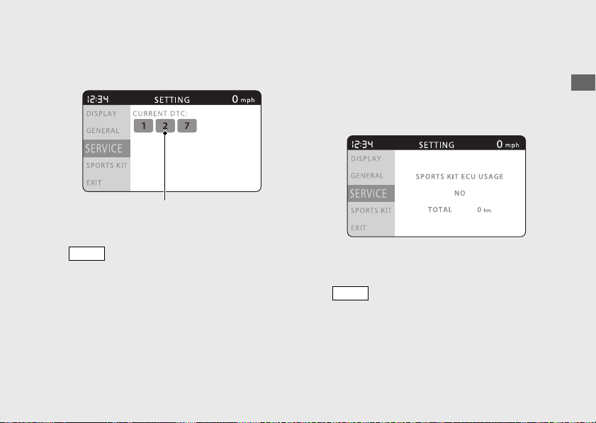
Reduce speed and have your motorcycle
inspected by your dealer as soon as possible.
To return to the upper level hierarchy, press
the
MODE
button.
#
SPORTS KIT ECU
“SPORTS KIT ECU USAGE” is displayed but
not usable.
To return to the upper level hierarchy, press
the
MODE
button.
20170830152249_31MKF6100_enu_BOOK Page 88 Wednesday, August 30 2017 15:45:50 JST
Operation Guide
85
Continued
DTC indexes
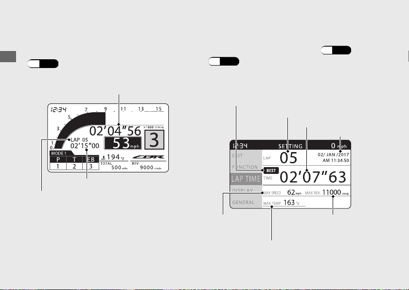
Lap Timer
You can record lap time in the circuit mode.
(P.24)
You can check and clear the recorded lap
time data in the setting mode. (P.55)
(P.56)
20170830152249_31MKF6100_enu_BOOK
Page 89 Wednesday, August 30 2017 15:45:50 JST
Operation Guide
86
Instruments (Continued)
Stopwatch/
difference with the best lap
Previous lap time
Previous lap number
Best icon
(Displayed when the fastest lap
time displayed.)
Lap number
Lap time
Time stamp
Maximum
vehicle
speed
Maximum coolant
temperature
Maximum engine
revolutions
The lap time data includes lap time, maximum
vehicle speed, maximum engine revolutions,
maximum coolant temperature, maximum
acceleration, maximum deceleration, maximum
left bank angle and maximum right bank angle.
(P.56)
Display range:
Previous lap number: 0 to 50
u Exceeds 50, repeats the “50”
Previous lap time: 00'00"00 to 99'59"99
u Exceeds 99'59"99, returns to the
“00'00"00”
Stopwatch: 00'00"00 to
99'59"99
u Exceeds 99'59"99, returns to the
“00'00"00”
Difference with the best lap:
-99'59"99 to 00'00"00 to +99'59"99
Maximum vehicle speed:
0 to 186
mph
(0 to 299 km/h)
Maximum engine revolutions:
0 to 20000 r/min (rpm)
Maximum coolant temperature:
-40 to 302°F (-40 to 150°C)
Maximum acceleration: 0 to 8.0 G
Maximum deceleration: 0 to 4.1 G
Maximum left bank angle:
0 to 90 deg
Maximum right bank angle:
0 to 90 deg
20170830152249_31MKF6100_enu_BOOK Page 90 Wednesday, August 30 2017 15:45:50 JST
Operation Guide
87
Continued
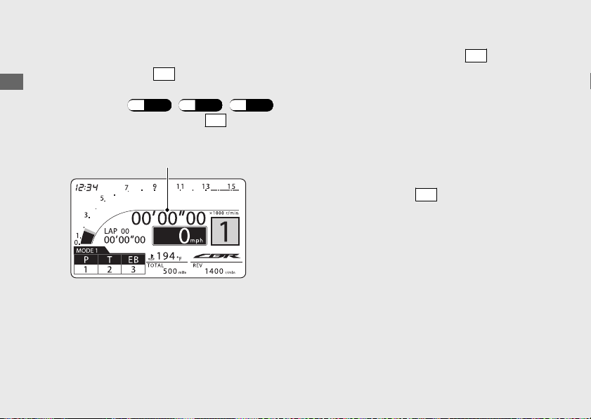
#
To Measure the Lap Time
a
Press and hold the
LAP
button or select the
“CIRCUIT” menu on the “DISPLAY MODE”
menu screen.
(P.24) (P.58) (P.59)
b
To start measuring, press the
LAP
button.
u The stopwatch starts measuring.
c
To record lap time, press the
LAP
button at
each lap.
u The stopwatch changes to display the
difference with the best lap.
After 10 seconds, the display will return
to the stopwatch.
u The previous lap time and previous lap
number change to the information of the
previous lap.
u If you press the
LAP
button again within
two seconds, lap time is not recorded.
u When exceeds 50 lap, the previous lap
number repeats the “LAP 50”.
20170830152249_31MKF6100_enu_BOOK Page 91 Wednesday, August 30 2017 15:45:50 JST
Operation Guide
88
Instruments (Continued)
Stopwatch
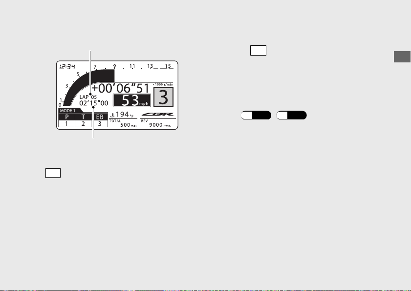
d
To end measurement, press and hold the
LAP
button.
To restart the measurement
Press the
LAP
button again. The stopwatch
restarts measuring.
u Measurement starts from the next lap.
#
To Check or Clear the Lap Time
Select the “LAP TIME” menu in the setting
mode.
(P.55) (P.57)
20170830152249_31MKF6100_enu_BOOK
Page 92 Wednesday, August 30 2017 15:45:50 JST
Operation Guide
89
Continued
Previous lap number
Previous lap time
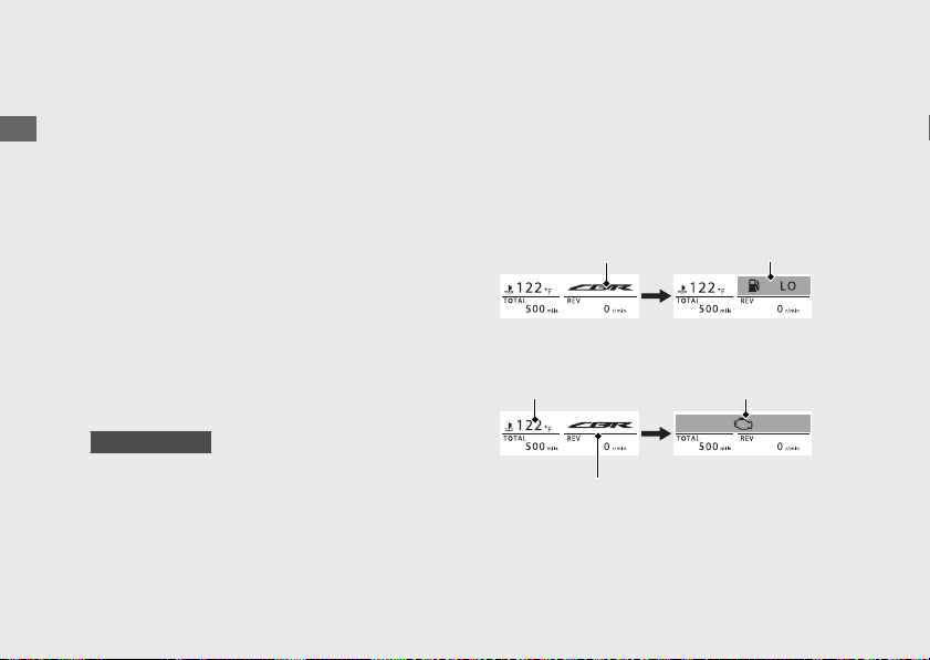
Pop-up information
In the following case, the INFO 3 display or
the INFO 3 display and coolant temperature
gauge change to a pop-up information
display.
● Maintenance information:
When the inspection time of your
motorcycle is approaching.
● Helpful information:
When your motorcycle has helpful
information.
● Failure information:
When your motorcycle has a problem
with the PGM-FI system.
CBR1000S1/S2
When your motorcycle has a problem
with the ÖHLINS Smart EC system.
When your motorcycle has multiple pieces of
information, each pop-up information display
appears alternately.
If your motorcycle has a problem with the
PGM-FI and ÖHLINS Smart EC system, the
failure information is displayed in priority to
other information.
20170830152249_31MKF6100_enu_BOOK Page 93 Wednesday, August 30 2017 15:45:50 JST
Operation Guide
90
Instruments (Continued)
INFO 3
INFO 3
Pop-up
information
display
Pop-up
information
display
Coolant
temperature
gauge
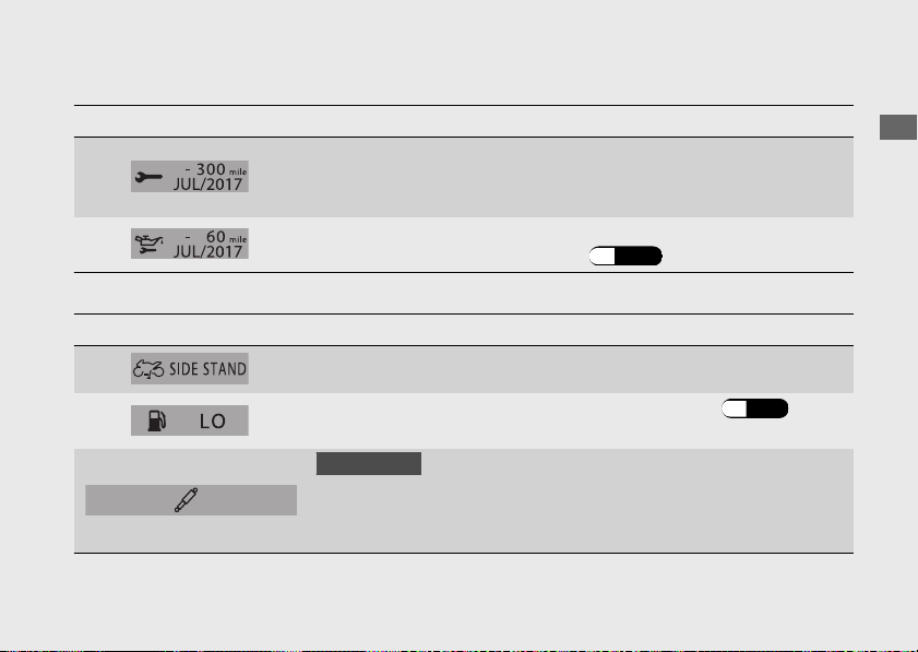
#
Maintenance Information
Indication Explanation Remedy
When the periodic inspection
time of your motorcycle is
approaching.
Have your motorcycle inspected
by your dealer.
When the oil change time of
your motorcycle is approaching.
Change the engine oil.
(P.145)
#
Helpful Information
Indication Explanation Remedy
When the side stand is down. Raise the side stand.
When remaining fuel is reached
1.1 US gal (4.0 L).
Fill the fuel tank. (P.111)
CBR1000S1/S2
When the suspension
initialization is waiting.
Stop your motorcycle. Wait for a
few seconds until the indication
turns off. If indication dose not
turn off, contact your dealer.
20170830152249_31MKF6100_enu_BOOK Page 94 Wednesday, August 30 2017 15:45:50 JST
Operation Guide
91
Continued
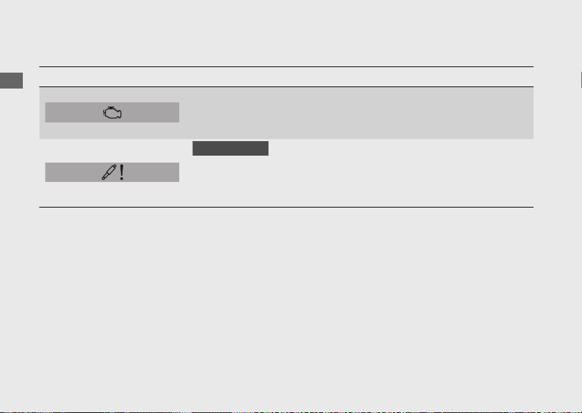
#
Failure Information
Indication Explanation Remedy
When your motorcycle has a
problem with the PGM-FI
system.
Reduce speed and have your
motorcycle inspected by your
dealer as soon as possible.
CBR1000S1/S2
When your motorcycle has a
problem with the ÖHLINS
Smart EC system.
Reduce speed and have your
motorcycle inspected by your
dealer as soon as possible.
20170830152249_31MKF6100_enu_BOOK Page 95 Wednesday, August 30 2017 15:45:50 JST
Operation Guide
92
Instruments (Continued)
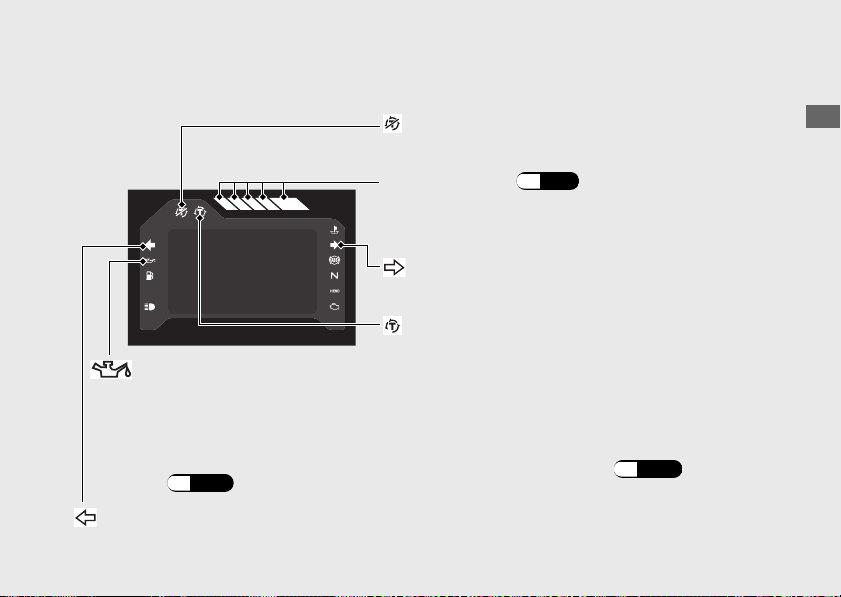
Indicators
20170830152249_31MKF6100_enu_BOOK Page 96 Wednesday, August 30 2017 15:45:50 JST
Operation Guide
93
Continued
If one of these indicators does not come on when it should, have your dealer check for
problems.
Torque Control indicator
● Comes on when the ignition switch is turned to
the ON position. Goes off when your speed
reaches approximately 3 mph (5 km/h)
to
indicate Torque Control is ready to work.
● Blinks when Torque Control is operating.
Torque Control OFF indicator
Comes on when the Torque Control is turned off.
Shift indicators (P.96)
Comes on briefly when the ignition switch is turned
to the ON position.
Right turn signal indicator
Left turn signal indicator
If it comes on while riding: (P.183)
Low oil pressure indicator
Comes on when the ignition switch is
turned to the ON
position. Goes off
when the engine starts.
If it comes on while engine is
running:
(P.181)
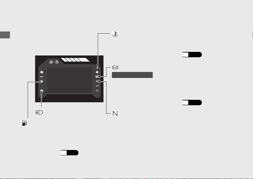
20170830152249_31MKF6100_enu_BOOK Page 97 Wednesday, August 30 2017 15:45:50 JST
Operation Guide
94
Indicators (Continued)
Neutral indicator
High coolant temperature indicator
Comes on briefly when the ignition switch is turned
to the ON position.
If it comes on while riding: (P.180)
ABS (Anti-lock Brake System) indicator
CBR1000RA/S1/S2
Comes on when the ignition switch is turned to the
ON position. Goes off when your speed reaches
approximately 6 mph (10 km/h).
If it comes on while riding:
(P.182)
Comes on when the transmission is in Neutral.
High beam indicator
Low fuel indicator
● Comes on briefly when the ignition switch is turned to the ON position.
● Comes on when there is only reserve fuel left in the fuel tank. Remaining fuel when low
fuel indicator comes on: 1.1 US gal (4.0 L)
If it comes on: (P.38)
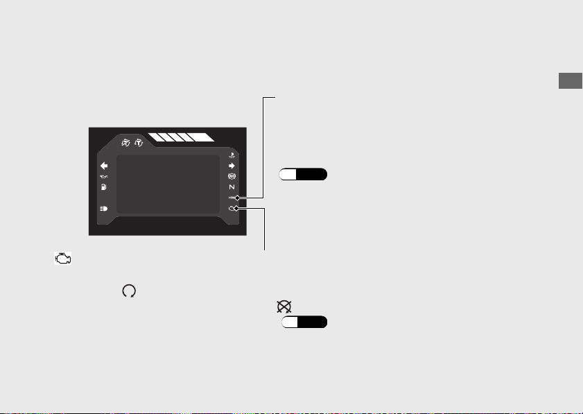
20170830152249_31MKF6100_enu_BOOK Page 98 Wednesday, August 30 2017 15:45:50 JST
Operation Guide
95
Continued
HESD (Honda Electronic Steering Damper)
indicator
Comes on briefly when the ignition switch is
turned to the ON position.
If it comes on while engine is running:
(P.182)
PGM-FI (Programmed Fuel Injection) malfunction indicator lamp (MIL)
Comes on briefly when the ignition switch is turned to the ON position with the engine stop
switch in the (Run) position. Comes on when the ignition switch is turned to the ON
position with the engine stop switch in the (Stop) position.
If it comes on while engine is running: (P.181)
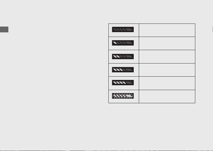
Shift Indicators
The shift indicators light or blink by the
engine revolutions. The first indicator lights
when the engine revolutions reach 800 r/min
(rpm) below a preset revolution number.
The second, third and fourth indicators will
light with each 200 r/min (rpm) rise.
All indicators will blink when engine
revolutions is reached the set value.
Setting of the shift indicators
You can change the engine revolutions at
which the shift indicators start blinking.
Initial setting:
OFF
Available setting range:
4,000 - 16,600 r/min (rpm)
Example set value: 11,600 r/min (rpm)
0 to 10,800 r/min (rpm)
All indicators go off
10,800 r/min (rpm)
First indicator comes on
11,000 r/min (rpm)
Second indicator comes on
11,200 r/min (rpm)
Third indicator comes on
11,400 r/min (rpm)
Fourth indicator comes on
11,600 r/min (rpm)
All indicators blink
20170830152249_31MKF6100_enu_BOOK Page 99 Wednesday, August 30 2017 15:45:50 JST
Operation Guide
96
Indicators (Continued)

20170830152249_31MKF6100_enu_BOOK Page 100 Wednesday, August 30 2017 15:45:50 JST
Operation Guide
97
BLANK PAGE
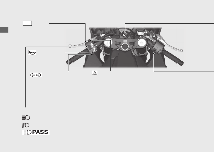
Switches
20170830152249_31MKF6100_enu_BOOK Page 101 Wednesday, August 30 2017 15:45:50 JST
Operation Guide
98
Headlight dimmer switch/Passing light control switch
•
: High beam
• : Low beam
Turn signal switch
Horn button
u Pressing the switch turns
the turn signal off.
Hazard switch
Switchable when the ignition switch is on. Can be
turned to off regardless of the ignition switch
position.
u The signals continue flashing with the ignition switch
is OFF or LOCK after the hazard switch is on.
LAP
button
Operate the lap timer
•
: Flashes the high beam headlight.
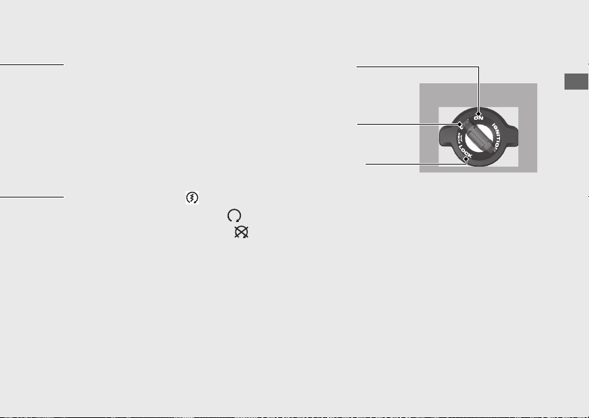
20170830152249_31MKF6100_enu_BOOK Page 102 Wednesday, August 30 2017 15:45:50 JST
Operation Guide
99
Continued
Ignition Switch
Switches the electrical system on/off, locks
the steering.
u Key can be removed when in the OFF or
LOCK position.
ON
OFF
Turns electrical system
on for starting/riding.
Turns engine off.
LOCK
Locks steering.
Engine stop switch/
Start button
Should normally remain in the (Run) position.
u In an emergency, switch to the (Stop) position to stop the engine.
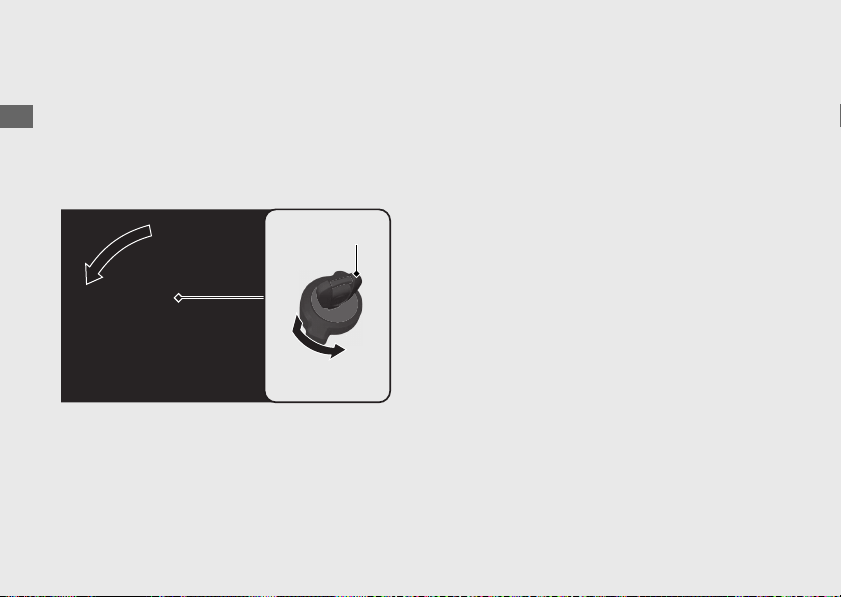
Steering Lock
Lock the steering when parking to help
prevent theft.
A U-shaped wheel lock or similar device is
also recommended.
#
Locking
a
Turn the handlebars all the way to the left.
b
Push the key down, and turn the ignition
switch to the LOCK position.
u Jiggle the handlebars if the lock is
difficult to engage.
c
Remove the key.
#
Unlocking
Insert the key, push it in, and turn the ignition
switch to the OFF position.
20170830152249_31MKF6100_enu_BOOK Page 103 Wednesday, August 30 2017 15:45:50 JST
Operation Guide
100
Switches (Continued)
Turn
Push
Ignition key
b
a
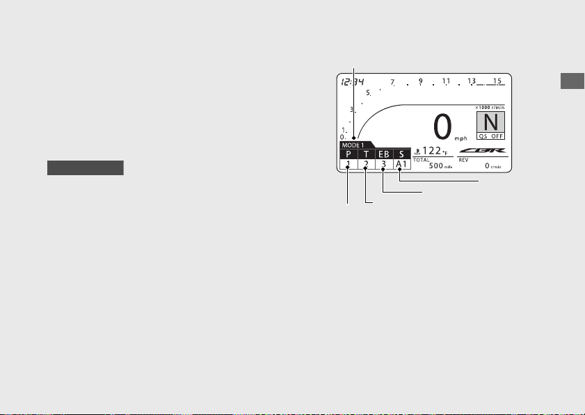
Riding mode
You can change the riding mode.
The riding mode consists of the following
parameters.
P: Engine output level
T: Torque control level
EB: Engine brake level
CBR1000S1/S2
S: Suspension mode
When “-” is displayed, go to your dealer for
service.
20170830152249_31MKF6100_enu_BOOK Page 104 Wednesday, August 30 2017 15:45:50 JST
Operation Guide
101
Continued
Current riding mode
P value
T value
EB value
S mode
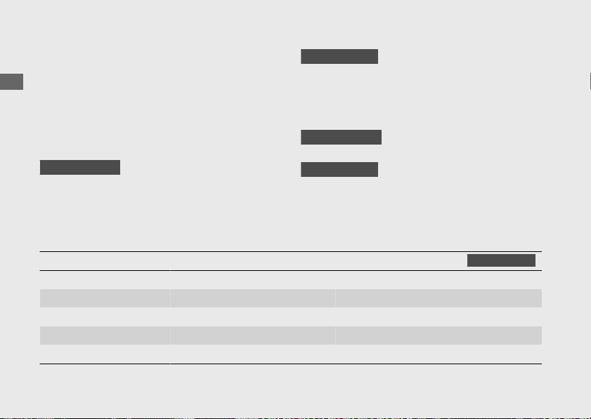
Initial setting
Riding modes
P value T value EB value S mode
CBR1000S1/S2
MODE 1 1 2 3 A1
*2
MODE 2 2 5 3 A2
*2
MODE 3 5 8 1 A3
*2
USER 1 1
*1
5
*1
1
*1
M1
*3
USER 2 2
*1
5
*1
2
*
1
M2
*3
Notes:
*1 : Value can be changed. *3 : S mode and setting of S mode can be changed
*2 : Setting of S mode can be changed
Riding mode has five modes.
Available riding mode:
MODE 1, MODE 2,
MODE 3, USER 1
and USER 2.
MODE 1, MODE 2 and MODE 3
u MODE 1 is suitable for track riding.
u MODE 2 is suitable for winding roads.
u MODE 3 is suitable for street riding.
CBR1000RR/RA
Each value can not be changed.
CBR1000S1/S2
Each value and mode can not be changed.
Setting of S mode can be changed.
USER 1 and USER 2
CBR1000RR/RA
Each value can be changed.
CBR1000S1/S2
Each value and mode can be changed.
Setting of S mode can be changed.
20170830152249_31MKF6100_enu_BOOK Page 105 Wednesday, August 30 2017 15:45:50 JST
Operation Guide
102
Riding mode (Continued)
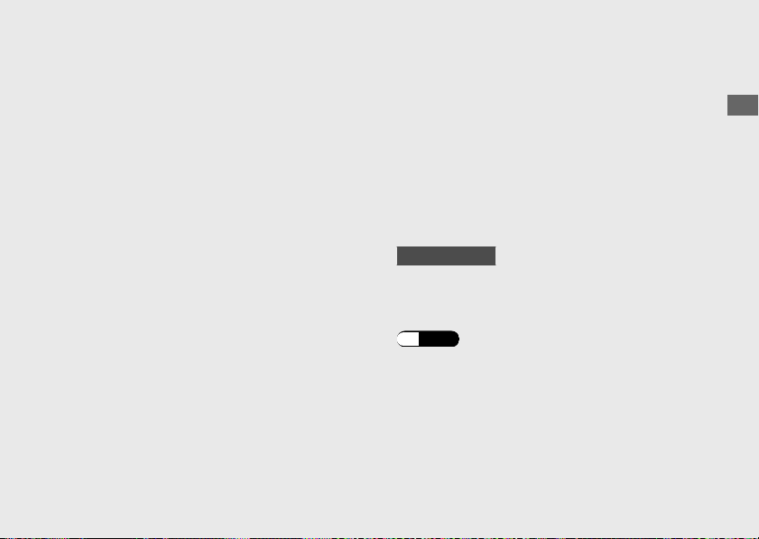
P value (Engine output level)
P value has five setting levels.
Available setting range: 1 to 5
u Level 1 has the most power.
u Level 5 has the least power.
T value (Torque control level)
T value has ten setting levels.
Available setting range: 0 to 9
u Level 1
is the minimum Torque Control level.
u
Level 9 is the maximum Torque Control level.
u Level 0 deactivates/turns off the Torque
Control.
EB value (Engine brake level)
EB value has three setting levels.
Available setting range:
1
to 3
u Level
1 has the strongest engine braking
effect.
u Level 3 has the weakest engine braking
effect.
S mode (Suspension mode)
CBR1000S1/S2
S mode has six modes.
Available modes: A1, A2, A3, M1, M2 and M3
Adjusting the ÖHLINS Smart EC system
(P.170)
20170830152249_31MKF6100_enu_BOOK Page 106 Wednesday, August 30 2017 15:45:50 JST
Operation Guide
103
Continued
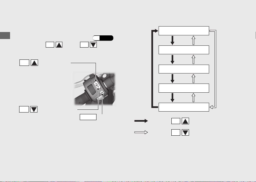
Selecting the riding mode
a
Stop the motorcycle.
b
Select the riding mode display. (P.102)
c
Press the
SEL
(up) or
SEL
(down)
button with the throttle fully closed.
20170830152249_31MKF6100_enu_BOOK Page 107 Wednesday, August 30 2017 15:45:50 JST
Operation Guide
104
Riding mode (Continued)
SEL
(up) button
SEL
(down) button
MODE
button
Press the
SEL
(up) button
Press the
SEL
(down) button
MODE 1
MODE 2
MODE 3
USER 1
USER 2
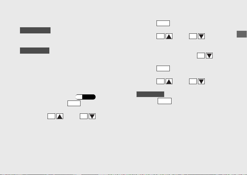
Setting the riding mode
CBR1000RR/RA
You can change the P, T and EB values on
the USER 1 and USER 2 of the riding mode.
CBR1000S1/S2
You can change the P, T, EB value and S
mode on the USER 1 and USER 2 of the
riding mode.
a
Stop the motorcycle.
b
Select the
USER 1 or USER 2 in the riding
mode you want to set.
(P.102)
c
Press and hold the
MODE
button until P
value is selected.
d
Press the
SEL
(up) or
SEL
(down)
button until the desired value is displayed.
e
Press the
MODE
button until T value is
selected.
f
Press the
SEL
(up) or
SEL
(down)
button until the desired value is displayed.
u T value can be changed to level 0 by
pressing and holding the
SEL
(down)
button at the time of level 1.
g
Press the
MODE
button until EB value is
selected.
h
Press the
SEL
(up) or
SEL
(down)
button until the desired value is displayed.
i
CBR1000S1/S2
Press the
MODE
button until S mode is
selected.
20170830152249_31MKF6100_enu_BOOK Page 108 Wednesday, August 30 2017 15:45:50 JST
Operation Guide
105
Continued
j
CBR1000S1/S2
Press the
SEL
(up) or
SEL
(down)
button until the desired mode is
displayed.
k
Press and hold the
MODE
button until
ordinary display is displayed.
You can stop setting the riding modes at any
time by pressing and holding the
MODE
button.
20170830152249_31MKF6100_enu_BOOK Page 109 Wednesday, August 30 2017 15:45:50 JST
Operation Guide
106
Riding mode (Continued)
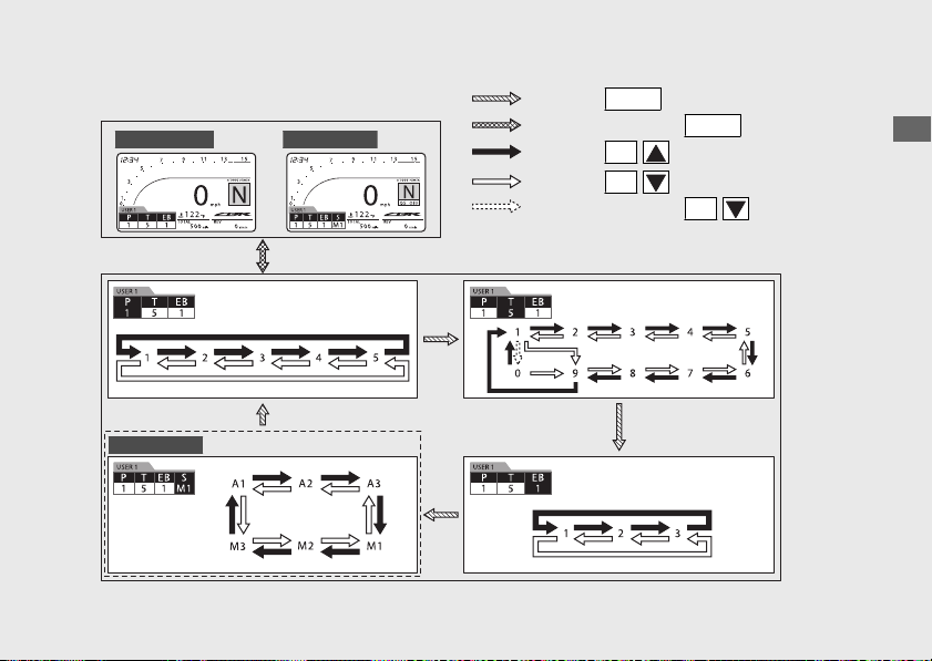
20170830152249_31MKF6100_enu_BOOK Page 110 Wednesday, August 30 2017 15:45:50 JST
Operation Guide
107
CBR1000RR/RA CBR1000S1/S2
CBR1000S1/S2
Press the
MODE
button
Press and hold the
MODE
button
Press the
SEL
(up) button
Press the
SEL
(down) button
Press and hold the
SEL
(down)
button
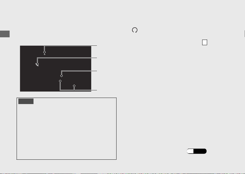
Starting the Engine
Start your engine using the following
procedure, regardless of whether the engine
is cold or warm.
NOTICE
•
If the engine does not start within 5 seconds, turn the
ignition switch to the OFF position and wait 10 seconds
before trying to start the engine again to recover
battery voltage.
•
Extended fast idling and revving the engine can
damage the engine, and the exhaust system.
•
Snapping the throttle or fast idling for more than about
5 minutes may cause exhaust pipe discoloration.
•
The engine will not start if the throttle is fully open.
a
Make sure the engine stop switch is in the
(Run) position.
b
Turn the ignition switch to the ON position.
c
Shift the transmission to Neutral (
N
indicator comes on). Alternatively, pull in the
clutch lever to start your motorcycle with the
transmission in gear so long as the side
stand is raised.
d
Press the start button with the throttle
completely closed.
If the engine does not start:
a
Open the throttle fully and press the start
button for 5 seconds.
b
Repeat the normal starting procedure.
c
If the engine starts, open the throttle slightly
if idling is unstable.
d
If the engine does not start, wait 10 seconds
before trying steps a & b again.
#
If Engine Will Not Start
(P.179)
20170830152249_31MKF6100_enu_BOOK
Page 111 Wednesday, August 30 2017 15:45:50 JST
Operation Guide
108
a
b
c
d
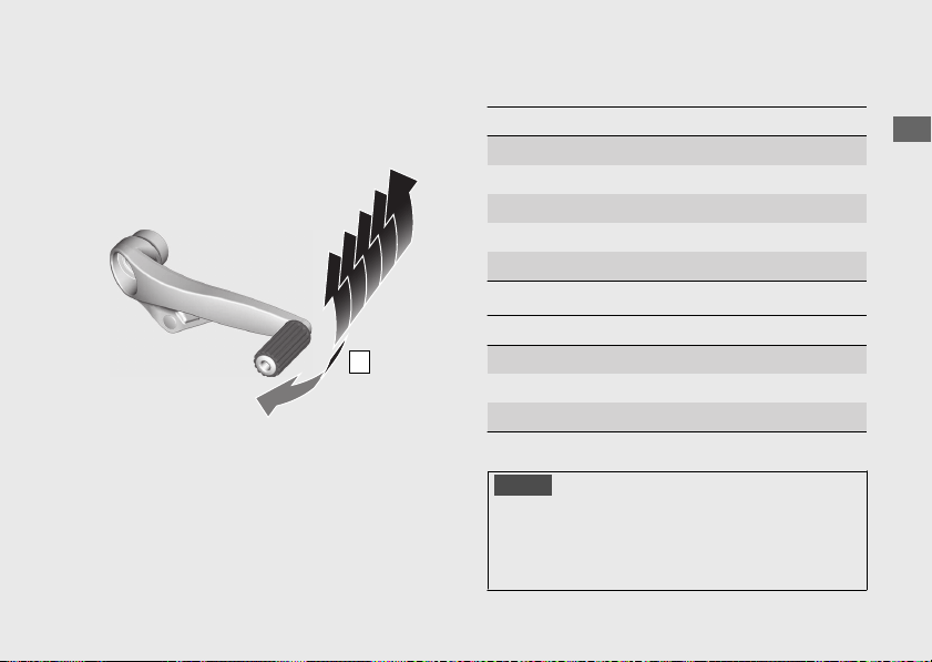
Shifting Gears
Your motorcycle transmission has 6 forward
gears in a one-down, five-up shift pattern.
If you put the motorcycle in gear with the
side stand down, the engine will shut off.
#
Recommended Shift Points
Shifting Up
From 1st to 2nd 12 mph (20 km/h)
From 2nd to 3rd 19 mph (30 km/h)
From 3rd to 4th 25 mph (40 km/h)
From 4th to 5th 31 mph (50 km/h)
From 5th to 6th 37 mph (60 km/h)
Shifting Down
From 6th to 5th 28 mph (45 km/h)
From 5th to 4th 22 mph (35 km/h)
From 4th to 3rd 16 mph (25 km/h)
NOTICE
Improper shifting can damage the engine,
transmission, and drive train. Also, coasting or
towing the motorcycle for long distances with
the engine off can damage the transmission.
20170830152249_31MKF6100_enu_BOOK Page 112 Wednesday, August 30 2017 15:45:50 JST
Operation Guide
109
Continued
1
2
3
4
5
6
N
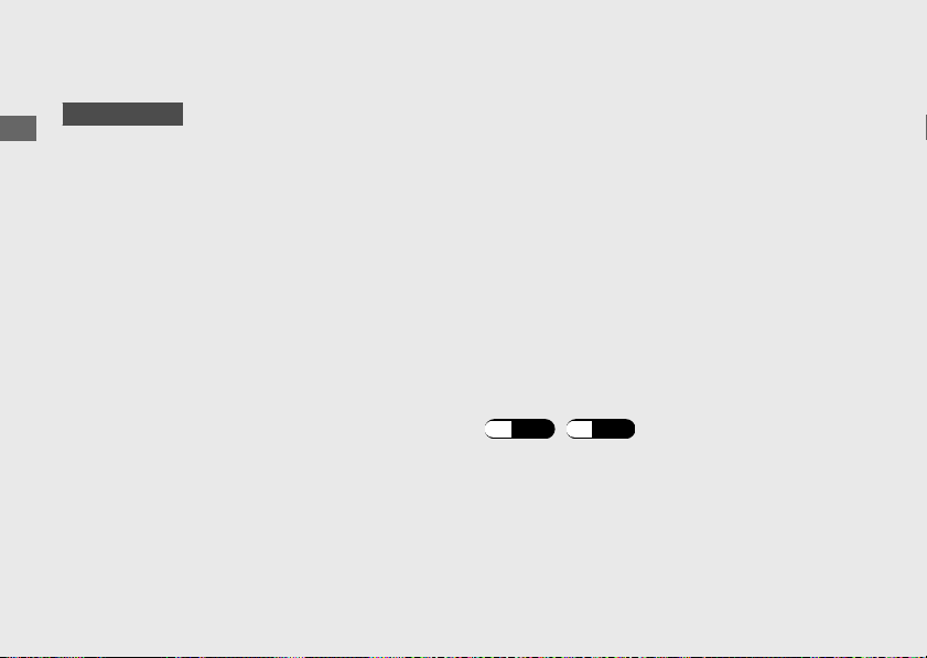
Quick Shifter
CBR1000S1/S2
This system enables very quick up and down
shifting without clutch and throttle
operations.
u This system does not function when
upshifting with the throttle closed.
u This system functions when the engine
speed is more than 1,500 r/min (rpm) on
upshifting or more than the idle speed on
downshifting.
u This system does not function when the
clutch lever is being operated.
● If “-” is displayed on the gear position
indicator, the Quick Shifter system does
not operate.
● If the Quick Shifter does not operate
normally, the clutch can be used to
complete the shift operation.
● The Quick Shifter can be individually
turned ON (active) and OFF (deactivate),
also the shift pedal load level for
activating the Quick Shifter can be
adjusted during up and down shifting.
● If the PGM-FI malfunction indicator lamp
comes on or the gear position indicator
flashes “-” in the current gear position, the
Quick Shifter system may not operate. If
either of the above occurs, contact your
dealer as soon as possible.
#
To Change the Setting of Quick Shifter
(P.45) (P.46)
20170830152249_31MKF6100_enu_BOOK Page 113 Wednesday, August 30 2017 15:45:50 JST
Operation Guide
110
Shifting Gears (Continued)
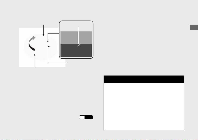
Refueling
Do not fill with fuel above the level plate.
Fuel type: Unleaded gasoline only
Recommended fuel octane number:
Pump Octane Number (PON) 91 or higher.
Tank capacity:
4.28 US gal (16.2 L)
#
Refueling and Fuel Guidelines
(P.14)
Opening the Fuel Fill Cap
Open the lock cover, insert the ignition key,
and turn it clockwise to open the fuel fill cap.
Closing the Fuel Fill Cap
a
After refueling, push the fuel fill cap closed
until it locks.
b
Remove the ignition key and close the lock
cover.
u The ignition key cannot be removed if
the fuel fill cap is not locked.
3WARNING
Gasoline is highly flammable and
explosive. You can be burned or
seriously injured when handling fuel.
• Stop the engine, and keep heat,
sparks, and flame away.
• Handle fuel only outdoors.
• Wipe up spills immediately.
20170830152249_31MKF6100_enu_BOOK Page 114 Wednesday, August 30 2017 15:45:50 JST
Operation Guide
111
Ignition key
Level plate
Fuel fill cap
Lock cover
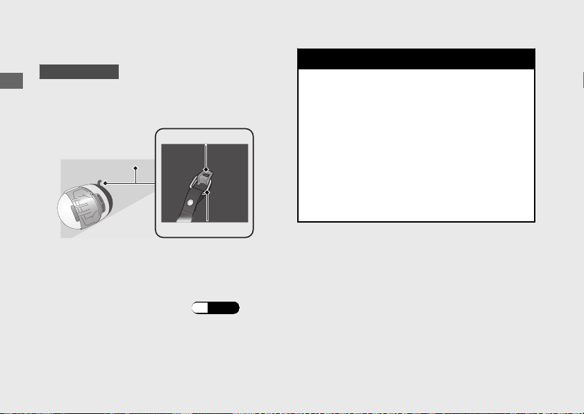
Storage Equipment
Helmet Holder
CBR1000RR/RA
The helmet holders are located on the
underside of the rear seat.
u Use the helmet holder only when parked.
#
Removing the Rear Seat
(P.140)
3WARNING
Riding with a helmet attached to the
holder can interfere with your ability to
safely operate the motorcycle and
could lead to a crash in which you can
be seriously hurt or killed.
Use the helmet holder only while
parked. Do not ride with a helmet
secured by the holder.
20170830152249_31MKF6100_enu_BOOK Page 115 Wednesday, August 30 2017 15:45:50 JST
Operation Guide
112
Helmet holder
Helmet D-ring
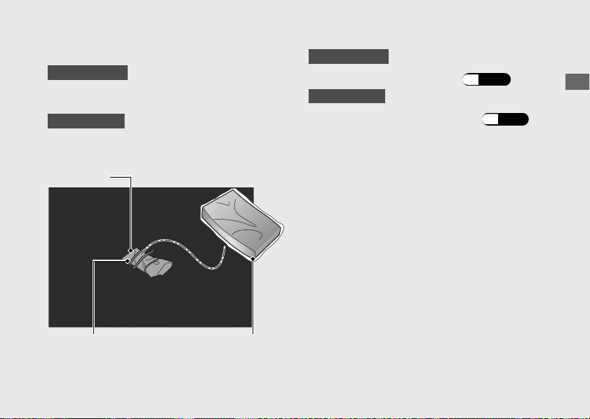
Tool Kit/Document Bag
CBR1000RR/RA
The tool kit and document bag are located
under the rear seat.
CBR1000S1/S2
The tool kit and document bag are located
under the single seat cowl.
CBR1000RR/RA
#
Removing the Rear Seat
(P.140)
CBR1000S1/S2
#
Removing Single Seat Cowl
(P.141)
20170830152249_31MKF6100_enu_BOOK
Page 116 Wednesday, August 30 2017 15:45:50 JST
Operation Guide
113
Rubber strap
Tool kit
Document bag

Importance of Maintenance......................... P. 115
Maintenance Schedule.................................
..P. 117
Maintenance Fundamentals .........................P. 120
Removing & Installing Body
Components...................................................P. 137
Battery.................................................................. P. 137
Front Seat............................................................P. 139
Rear Seat............................................................. P. 140
Single Seat Cowl................................................ P. 141
Under Cowl......................................................... P. 142
Engine Oil..........................................................P. 143
Coolant .............................................................. P. 147
Brakes................................................................. P. 149
Side Stand ......................................................... P. 152
Drive Chain ....................................................... P. 153
Clutch .................................................................P. 157
Throttle .............................................................. P. 161
Other Adjustments.......................................... P. 162
Adjusting the Headlight Aim..........................P. 162
Adjusting the Brake Lever...............................P. 163
Adjusting the Front Suspension ....................P. 164
Adjusting the Rear Suspension...................... P. 167
Adjusting the ÖHLINS Smart EC System.....P. 170
20170830152249_31MKF6100_enu_BOOK Page 117 Wednesday, August 30 2017 15:45:50 JST
Please read “Importance of Maintenance” and “Maintenance Fundamentals” carefully
before attempting any maintenance. Refer to “Specifications” for service data.
An optional larger tool kit may be available.
Check with your Honda dealer's parts department.
Maintenance
Importance of Maintenance
Importance of Maintenance
Keeping your motorcycle well-maintained is
absolutely essential to your safety and to
protect your investment, obtain maximum
performance, avoid breakdowns, and reduce air
pollution. Maintenance is the owner's
responsibility. Be sure to inspect your
motorcycle before each ride, and perform the
periodic checks specified in the Maintenance
Schedule. 2 P. 117
3WARNING
Improperly maintaining your
motorcycle or failing to correct a
problem before you ride can cause a
crash in which you can be seriously hurt
or killed.
Always follow the inspection and
maintenance recommendations and
schedules in this owner's manual.
For information about the exhaust emission and
noise emission requirements of the U.S.
Environmental Protection Agency (EPA), the
California Air Resources Board (CARB), and the
Environment and Climate Change Canada
(ECCC). 2 P. 211
USA
Maintenance, replacement or repair of the
emission control devices and systems may
be performed by any motorcycle repair
establishment or individual using parts
that are “certified” to EPA standards.
20170830152249_31MKF6100_enu_BOOK Page 118 Wednesday, August 30 2017 15:45:50 JST
Maintenance
115

Maintenance Safety
Always read the maintenance instructions
before you begin each task, and make sure that
you have the tools, parts, and skills required.
We cannot warn you of every conceivable
hazard that can arise in performing
maintenance. Only you can decide whether or
not you should perform a given task.
Follow these guidelines when performing
maintenance.
● Stop the engine and remove the key.
● Place your motorcycle on a firm, level
surface using the side stand or a
maintenance stand to provide support.
● Allow the engine, muffler, brakes, and other
high-temperature parts to cool before
servicing as you can get burned.
● Run the engine only when instructed, and
do so in a well-ventilated area.
20170830152249_31MKF6100_enu_BOOK Page 119 Wednesday, August 30 2017 15:45:50 JST
Importance of Maintenance
Maintenance
116

Maintenance Schedule
The maintenance schedule specifies the
maintenance requirements necessary to
ensure safe, dependable performance, and
proper emission control.
Maintenance work should be performed in
accordance with Honda's standards and
specifications by properly trained and
equipped technicians. Your dealer meets all
of these requirements. Keep an accurate
record of maintenance to help ensure that
your motorcycle is properly maintained.
Make sure that whomever performs the
maintenance completes this record.
All scheduled maintenance is considered a
normal owner operating cost and will be
charged to you by your dealer. Retain all
receipts. If you sell the motorcycle, these
receipts should be transferred with the
motorcycle to the new owner.
20170830152249_31MKF6100_enu_BOOK Page 120 Wednesday, August 30 2017 15:45:50 JST
Maintenance
117
Continued
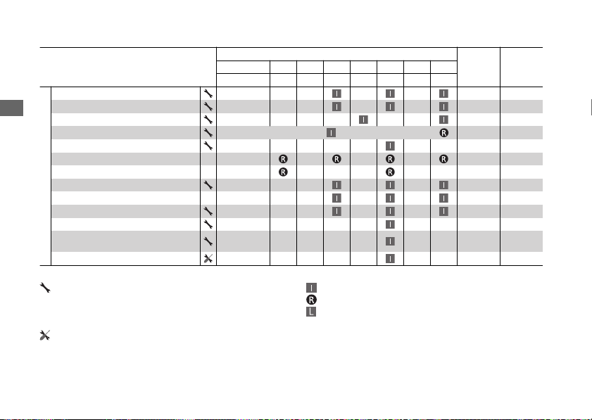
Items
Frequency
*1
Regular
Replace
Refer to
page
× 1,000 mi 0.6 4 8 12 16 20 24
× 1,000 km 1.0 6.4 12.8 19.2 25.6 32.0 38.4
Emission-related Items
Fuel Line
–
Throttle Operation 161
Air Cleaner
*2
–
Spark Plug
Every 16,000 mi (25,600 km): Every 32,000 mi (51,200 km):
–
Valve Clearance –
Engine Oil 1 Year 145
Engine Oil Filter 145
Engine Idle Speed –
Radiator Coolant
*4
3 Years 147
Cooling System –
Secondary Air Supply System –
Evaporative Emission Control System
*3
–
Exhaust Gas Control Actuator Cable –
Maintenance Level Maintenance Legend
:
Intermediate. We recommend service by your dealer, unless
you have the necessary tools and are mechanically skilled.
Procedures are provided in an official Honda Service
Manual (2 P. 217).
:
:
:
Inspect (clean, adjust, lubricate, or replace, if necessary)
Replace
Lubricate
:
Technical. In the interest of safety, have your motorcycle
serviced by your dealer.
20170830152249_31MKF6100_enu_BOOK Page 121 Wednesday, August 30 2017 15:45:50 JST
Maintenance Schedule
Maintenance
118
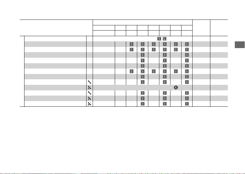
Items
Frequency
*1
Regular
Replace
Refer to
page
× 1,000 mi 0.6 4 8 12 16 20 24
× 1,000 km 1.0 6.4 12.8 19.2 25.6 32.0 38.4
Non-Emission-related Items
Drive Chain
Every 600 mi (1,000 km):
,
153
Brake Fluid
*4
2 Years 149
Brake Pads Wear 150
Brake System 120
Brake light Switch 151
Headlight Aim 162
Clutch System 157
Side Stand 152
Suspension 164
Front Fork Oil (CBR1000S1/S2)
Every 18,000 mi (30,000 km) or 36 months:
–
Nuts, Bolts, Fasteners –
Wheels/Tire 133
Steering Head Bearings –
Notes:
*
1 : At higher odometer reading, repeat at the frequency interval established here.
*
2 : Service more frequently when riding in unusually wet or dusty areas.
*
3 : 50 STATE (meets California).
*
4 : Replacement requires mechanical skill.
20170830152249_31MKF6100_enu_BOOK Page 122 Wednesday, August 30 2017 15:45:50 JST
Maintenance Schedule
Maintenance
119

Maintenance Fundamentals
Pre-ride Inspection
To ensure safety, it is your responsibility to
perform a pre-ride inspection and make sure
that any problem you find is corrected. A pre-
ride inspection is a must, not only for safety, but
because having a breakdown, or even a flat tire,
can be a major inconvenience.
Check the following items before you get on
your motorcycle:
● Tire tread wear and air pressures are within
limits. 2 P. 133
● Lights, horn, and turn signals operate
normally.
● Check the condition of the drive chain.
Adjust slack and lubricate as needed.
2 P. 131
● Combined weight is within load limits.
2 P. 223
● Cargo is secured properly.
● Suspension is adjusted to suit load. 2 P. 164,
2 P. 167
Check the following items after you get on your
motorcycle:
● Throttle action moves smoothly without
binding. 2 P. 161
● Brake lever and pedal operate normally.
● Refuel when needed. 2 P. 14, 2 P. 111
● Engine stop switch functions properly.
2 P. 98
Check the following items at regular intervals:
● Oil level is between the upper and lower
level marks. 2 P. 143
● Brake fluid level is
Front: between the UPPER and LOWER level
marks. 2 P. 149
Rear: between the UPPER and LOWER level
marks. 2 P. 149
● Engine coolant level is between the UPPER
and LOWER level marks. 2 P. 147
● Side stand functions properly. 2 P. 152
20170830152249_31MKF6100_enu_BOOK Page 123 Wednesday, August 30 2017 15:45:50 JST
Maintenance
120
Tires and wheels
Check the air pressure (2 P. 133), examine tread for wear and
damage (2 P. 133), and check the wheels for damage.
Fluid levels
Check the engine oil level (2 P. 143), engine coolant level (2 P. 147
),
and brake fluid level (2 P. 149).
Lights
Check that the headlight, position light, brake light, taillight, turn
signals and license plate light are working properly.
Controls
Check the freeplay of the clutch lever (2 P. 157) and throttle grip
(2 P. 161).
Drive chain
Check the slack (2 P. 153), adjust the slack (2 P. 154), and lubricate
(2 P. 131) as needed.
Fuses Check that you have a full supply of spare fuses.
Nuts & bolts Check the major nuts and bolts, and tighten as needed.
Periodic Checks
You should also perform other periodic
maintenance checks at least once a month
regardless of how often you ride, or more often
if you ride frequently.
Also, check the odometer reading against the
Maintenance Schedule and perform all
maintenance that is due. 2 P. 117
20170830152249_31MKF6100_enu_BOOK Page 124 Wednesday, August 30 2017 15:45:50 JST
Maintenance Fundamentals
Maintenance
121
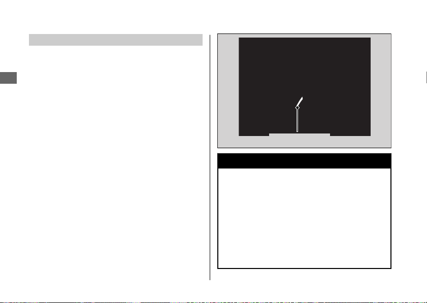
Replacing Parts
Always use Honda Genuine Parts or their
equivalents to ensure reliability and safety.
When ordering colored components, specify
the model name, color, and code mentioned on
the color label.
The color label is attached on the inside of the
left duct.
3WARNING
Installing non-Honda parts may make
your motorcycle unsafe and cause a
crash in which you can be seriously hurt
or killed.
Always use Honda Genuine Parts or
equivalents that have been designed
and approved for your motorcycle.
20170830152249_31MKF6100_enu_BOOK Page 125 Wednesday, August 30 2017 15:45:50 JST
Maintenance Fundamentals
Maintenance
122
Color label
Battery
CBR1000S1/S2
Your motorcycle has a lithium-ion (li-ion)
battery. 2 P. 125
CBR1000RR/RA
Your motorcycle has a maintenance-free type
battery. You do not have to check the battery
electrolyte level or add distilled water. Clean the
battery terminals if they become dirty or
corroded.
Do not remove the battery cap seals. There is
no need to remove the cap when charging.
NOTICE
An improperly disposed of battery can be
harmful to the environment and human health.
Always confirm local regulations for proper
battery disposal instruction.
#
What to do in an emergency
If any of the following occur, immediately see
your doctor.
● Electrolyte splashes into your eyes:
u Wash your eyes repeatedly with cool
water for at least 15 minutes. Using water
under pressure can damage your eyes.
● Electrolyte splashes onto your skin:
u Remove affected clothing and wash your
skin thoroughly using water.
20170830152249_31MKF6100_enu_BOOK Page 126 Wednesday, August 30 2017 15:45:50 JST
Maintenance Fundamentals
Maintenance
123
Continued
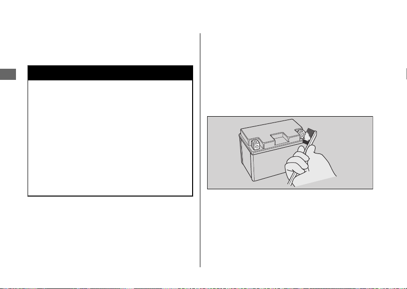
● Electrolyte splashes into your mouth:
u Rinse mouth thoroughly with water, and
do not swallow.
3WARNING
The battery gives off explosive hydrogen
gas during normal operation.
A spark or flame can cause the battery to
explode with enough force to kill or
seriously hurt you.
Wear protective clothing and a face
shield, or have a skilled mechanic do the
battery servicing.
WARNING: Battery posts, terminals, and
related accessories contain lead and lead
compounds.
Wash your hands after handling.
#
Cleaning the Battery Terminals
1.
Remove the battery. 2 P. 137
2.
If the terminals are starting to corrode and
are coated with a white substance, wash
with warm water and wipe clean.
3.
If the terminals are heavily corroded, clean
and polish the terminals with a wire brush or
sandpaper. Wear safety glasses.
4.
After cleaning, reinstall the battery.
The battery has a limited life span. Consult your
dealer about when you should replace the
battery. Always replace the battery with another
maintenance-free battery of the same type.
20170830152249_31MKF6100_enu_BOOK Page 127 Wednesday, August 30 2017 15:45:50 JST
Maintenance Fundamentals
Maintenance
124

#
Charging
If you use electrical accessories that drain the
battery or you do not ride frequently, we
recommend that you charge the battery every
30 days using a charger designed specifically for
your Honda, which can be purchased from your
dealer. Read the information that came with
your battery charger and follow the instructions
on the battery. Avoid using an automobile-type
battery charger, as these can overheat a
motorcycle battery and cause permanent
damage.
Make sure the ignition switch is in the OFF
position before charging the battery.
NOTICE
Improper charging can damage the battery. If
you can’t charge the battery or it appears unable
to hold a charge, contact your dealer.
NOTICE
Jump starting using an automobile battery can
damage your motorcycle's electrical system and
is not recommended. Bump starting is also not
recommended.
NOTICE
Installing non-Honda electrical accessories can
overload the electrical system, discharging the
battery and possibly damaging the system.
Lithium-Ion (Li-Ion) Battery
CBR1000S1/S2
Your motorcycle has a lithium-ion (li-ion)
battery. Clean the battery terminals if they
become dirty or corroded.
NOTICE
An improperly disposed of battery can be
harmful to the environment and human health.
Always confirm local regulations for proper
battery disposal instruction.
20170830152249_31MKF6100_enu_BOOK Page 128 Wednesday, August 30 2017 15:45:50 JST
Maintenance Fundamentals
Maintenance
125
Continued
#
What to do in an emergency
If any of the following occurs, immediately see
your doctor.
● Electrolyte splashes into your eyes:
u Wash your eyes repeatedly with cool
water for at 15 minutes. Using water
under pressure can damage your eyes.
● Electrolyte splashes onto your skin:
u Remove affected clothing and wash your
skin thoroughly using water.
● Electrolyte splashes into your mouth
u Rinse mouth thoroughly with water, and
do not swallow.
3WARNING
The battery contains flammable organic
solvent as electrolyte.
You can be burned or seriously injured
if the battery is handled improperly.
● Keep the battery away from heat,
sparks, and flame.
● Keep the battery out of the reach of
children.
● Do not disassemble or modify the
battery or battery terminals.
● Do not short-circuit the battery with
metal tools or other metal objects.
● Do not subject the battery to
impacts.
20170830152249_31MKF6100_enu_BOOK Page 129 Wednesday, August 30 2017 15:45:50 JST
Maintenance Fundamentals
Maintenance
126
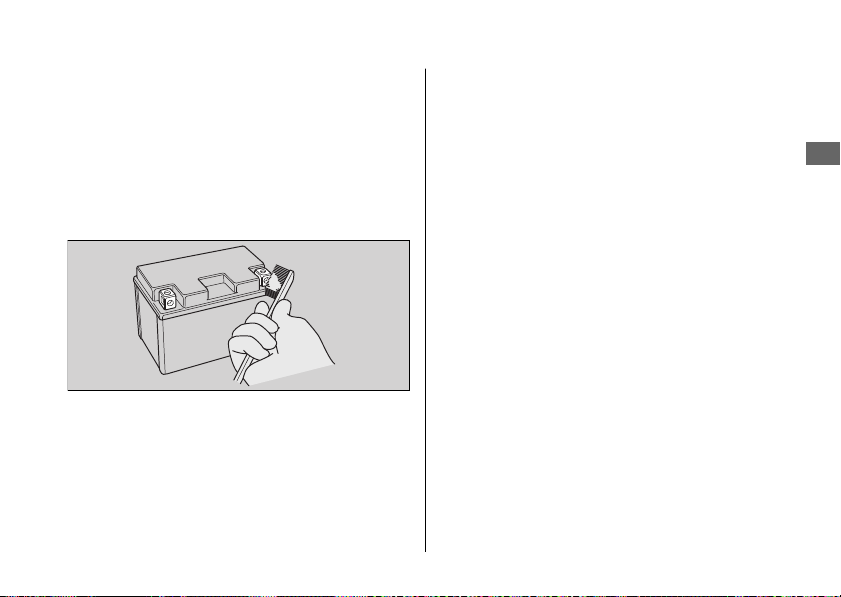
#
Cleaning the Battery Terminals
1.
Remove the battery. 2 P. 137
2.
If the terminals are starting to corrode and
are coated with a white substance, wash
with warm water and wipe clean.
3.
If the terminals are heavily corroded, clean
and polish the terminals with a wire brush or
sandpaper. Wear safety glasses.
4.
After cleaning, reinstall the battery.
The battery has a limited life span. Consult your
dealer about when you should replace the
battery. Always replace the battery with another
lithium-ion (li-ion) battery of the same type.
20170830152249_31MKF6100_enu_BOOK Page 130 Wednesday, August 30 2017 15:45:50 JST
Maintenance Fundamentals
Maintenance
127
Continued

#
Charging
If you use electrical accessories that drain the
battery or you do not ride frequently, we
recommend that you charge the battery every
30 days using a charger recommended by your
lithium-ion (li-ion) battery manufacturer.
Contact your dealer before charging the
battery.
Make sure the ignition switch is in the OFF
position before charging the battery.
NOTICE
Only use a charger recommended by your
lithium-ion (li-ion) battery manufacturer. Using a
battery charger that is not recommended can
cause permanent damage to your battery.
NOTICE
Improper charging can damage the battery. If
you can’t charge the battery or it appears unable
to hold a charge, contact your dealer.
NOTICE
Do not jump-start, as this can damage your
motorcycle's electrical system and battery.
Bump starting is not recommended.
NOTICE
Installing non-Honda electrical accessories can
overload the electrical system, discharging the
battery and possibly damaging the system.
20170830152249_31MKF6100_enu_BOOK Page 131 Wednesday, August 30 2017 15:45:50 JST
Maintenance Fundamentals
Maintenance
128
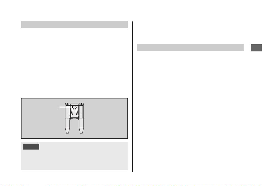
Fuses
Fuses protect the electrical circuits on your
motorcycle. If something electrical on your
motorcycle stops working, check for and
replace any blown fuses. 2 P. 197
#
Inspecting and Replacing Fuses
Turn the ignition switch to the OFF position to
remove and inspect fuses. If a fuse is blown,
replace with a fuse of the same rating. For fuse
ratings, see “Specifications.” 2 P. 225
NOTICE
Replacing a fuse with one that has a higher
rating greatly increases the chance of damage to
the electrical system.
If a fuse fails repeatedly, you likely have an
electrical fault. Have your motorcycle inspected
by your dealer.
Engine Oil
Engine oil consumption varies and oil quality
deteriorates according to riding conditions and
time elapsed.
Check the engine oil level regularly, and add the
recommended engine oil if necessary. Dirty oil or
old oil should be changed as soon as possible.
#
Selecting the Engine Oil
For recommended engine oil, see
“Specifications.” 2 P. 224
If you use non-Honda engine oil, check the
label to make sure that the oil satisfies all of the
following standards:
● JASO T 903 standard
*1
: MA
● SAE standard
*2
: 10W-30
● API classification
*3
: SG or higher
20170830152249_31MKF6100_enu_BOOK Page 132 Wednesday, August 30 2017 15:45:50 JST
Maintenance Fundamentals
Maintenance
129
Continued
Blown fuse
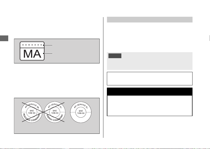
*1.
The JASO T 903 standard is an index for engine
oils for 4-stroke motorcycle engines. There are
two classes: MA and MB. For example, the
following label shows the MA classification.
*2.
The SAE standard grades oils by their viscosity.
*3.
The API classification specifies the quality and
performance rating of engine oils. Use SG or
higher oils, excluding oils marked as “Energy
Conserving” or “Resource Conserving” on the
circular API service symbol.
Brake Fluid
Do not add or replace brake fluid, except in an
emergency. Use only fresh brake fluid from a
sealed container. If you do add fluid, have the
brake system serviced by your dealer as soon as
possible.
NOTICE
Brake fluid can damage plastic and painted surfaces.
Wipe up spills immediately and wash thoroughly.
Recommended brake fluid:
Honda DOT 4 Brake Fluid or equivalent
3WARNING
Clean filler cap before removing. Use
only DOT 4 fluid from a sealed
container.
20170830152249_31MKF6100_enu_BOOK Page 133 Wednesday, August 30 2017 15:45:50 JST
Maintenance Fundamentals
Maintenance
130
Oil code
Oil classification
Not recommended Recommended
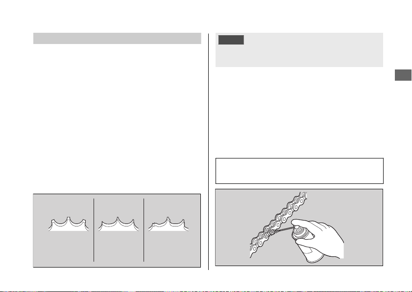
Drive Chain
The drive chain must be inspected and
lubricated regularly. Inspect the chain more
frequently if you often ride on bad roads, ride at
high speed, or ride with repeated fast
acceleration. 2 P. 153
If the chain does not move smoothly, makes
strange noises, has damaged rollers, has loose
pins, has missing O-rings, or kinks, have the
chain inspected by your dealer.
Also inspect the drive sprocket and driven
sprocket. If either has worn or damaged teeth,
have the sprocket replaced by your dealer.
NOTICE
Use of a new chain with worn sprockets will cause
rapid chain wear.
#
Cleaning and Lubricating
After inspecting the slack, clean the chain and
sprockets while rotating the rear wheel. Use a dry
cloth with chain cleaner designed specifically for
O-ring chains, or neutral detergent. Use a soft
brush if the chain is dirty.
After cleaning, wipe dry and lubricate with the
recommended lubricant.
Recommended lubricant:
Pro Honda HP Chain Lube or equivalent
20170830152249_31MKF6100_enu_BOOK Page 134 Wednesday, August 30 2017 15:45:50 JST
Maintenance Fundamentals
Maintenance
131
Continued
Normal
(GOOD)
Worn
(REPLACE)
Damaged
(REPLACE)
Do not use a steam cleaner, a high pressure
cleaner, a wire brush, volatile solvent such as
gasoline and benzene, abrasive cleaner, chain
cleaner or lubricant NOT designed specifically
for O-ring chains as these can damage the
rubber O-ring seals.
Avoid getting lubricant on the brakes or tires.
Avoid applying excess chain lubricant to prevent
spray onto your clothes and the motorcycle.
Recommended Coolant
Pro Honda HP Coolant is a pre-mixed solution
of antifreeze and distilled water.
Concentration:
50% antifreeze and 50% distilled water
A concentration of antifreeze below 40% will
not provide proper corrosion and cold
temperature protection.
A concentration of up to 60% will provide better
protection in colder climates.
NOTICE
Using coolant not specified for aluminum engines
or tap/mineral water can cause corrosion.
20170830152249_31MKF6100_enu_BOOK Page 135 Wednesday, August 30 2017 15:45:50 JST
Maintenance Fundamentals
Maintenance
132
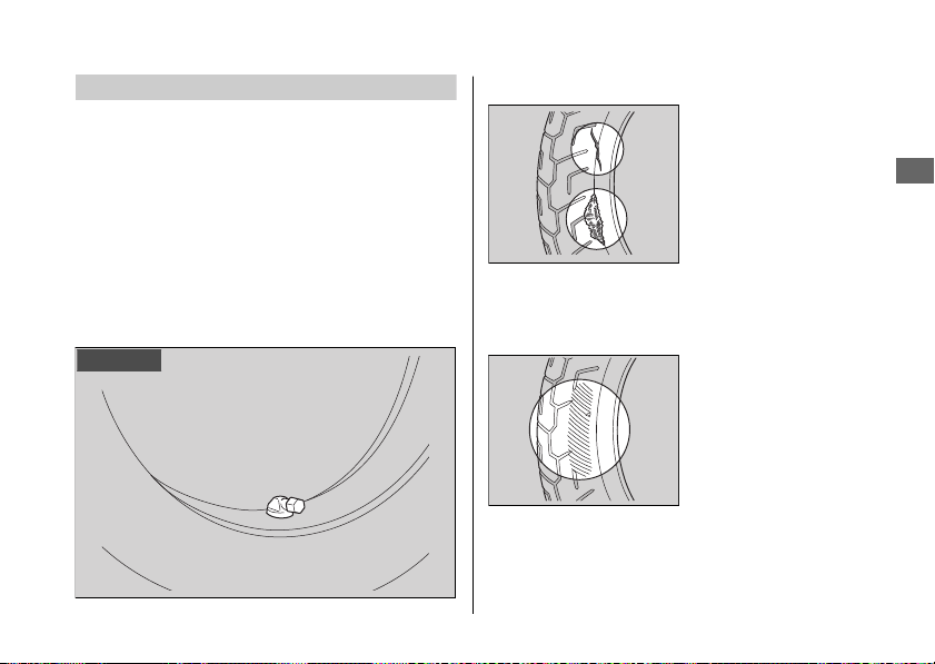
Tires (Inspecting/Replacing)
#
Checking the Air Pressure
Visually inspect your tires and use an air
pressure gauge to measure the air pressure at
least once a month or any time you think the
tires look low. Always check air pressure when
your tires are cold.
Even if the direction of the valve stem is
changed, do not return it to the original
position. Have your motorcycle inspected by
your dealer.
#
Inspecting for Damage
Inspect the tires for
cuts, slits, or cracks that
exposes fabric or
cords, or nails or other
foreign objects
embedded in the side
of the tire or the tread.
Also inspect for any unusual bumps or bulges in
the side walls of the tires.
#
Inspecting for Abnormal Wear
Inspect the tires for
signs of abnormal wear
on the contact surface.
20170830152249_31MKF6100_enu_BOOK Page 136 Wednesday, August 30 2017 15:45:50 JST
Maintenance Fundamentals
Maintenance
133
Continued
Right side
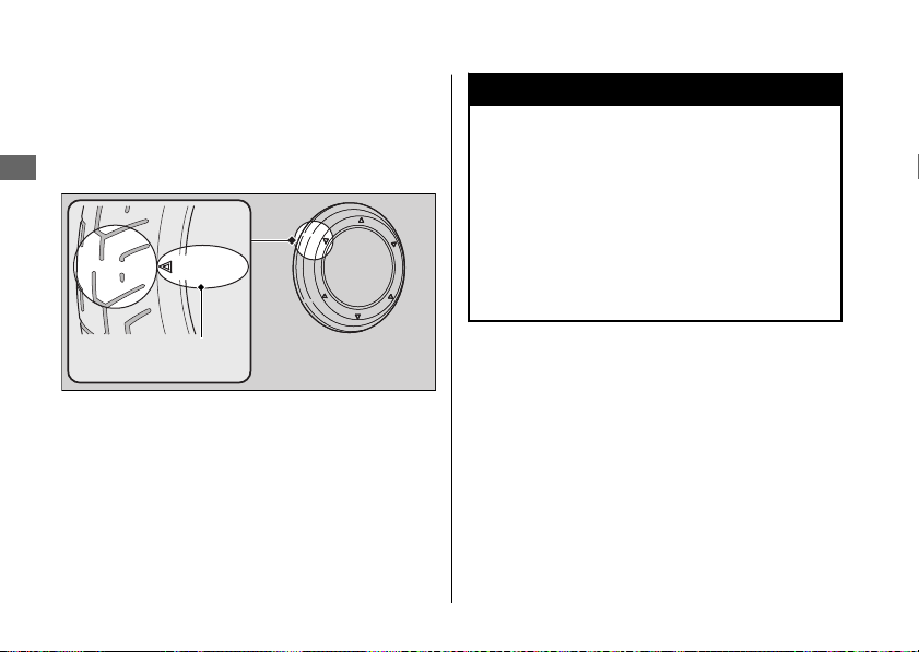
#
Inspecting Tread Depth
Inspect the tread wear indicators. If they
become visible, replace the tires immediately.
For safe riding, you should replace the tires
when the minimum tread depth is reached.
3WARNING
Riding on tires that are excessively worn
or improperly inflated can cause a crash
in which you can be seriously hurt or
killed.
Follow all instructions in this owner's
manual regarding tire inflation and
maintenance.
20170830152249_31MKF6100_enu_BOOK Page 137 Wednesday, August 30 2017 15:45:50 JST
Maintenance Fundamentals
Maintenance
134
Wear indicator
location mark
or TWI

Have your tires replaced by your dealer.
For recommended tires, air pressure and
minimum tread depth, see “Specifications.”
2 P. 224
Follow these guidelines whenever you replace
tires.
● Use the recommended tires or equivalents
of the same size, construction, speed rating,
and load range.
● Have the wheel balanced with Honda
Genuine balance weights or equivalent after
the tire is installed.
● Do not install a tube inside a tubeless tire on
this motorcycle. Excessive heat build-up can
cause the tube to burst.
● Use only tubeless tires on this motorcycle.
The rims are designed for tubeless tires, and
during hard acceleration or braking, a tube-
type tire could slip on the rim and cause the
tire to rapidly deflate.
3WARNING
Installing improper tires on your
motorcycle can adversely affect
handling and stability, and can cause a
crash in which you can be seriously hurt
or killed.
Always use the size and type of tires
recommended in this owner's manual.
20170830152249_31MKF6100_enu_BOOK Page 138 Wednesday, August 30 2017 15:45:50 JST
Maintenance Fundamentals
Maintenance
135
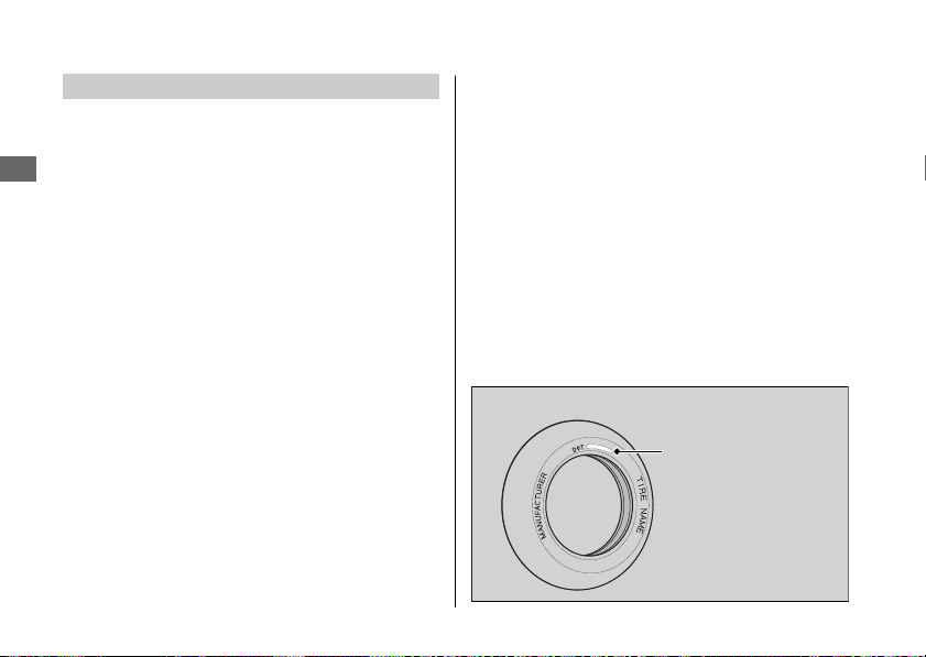
Tire Service Life
The service life of your tires is dependent on
many factors, including, but not limited to,
riding habits, road conditions, vehicle loading,
tire air pressure, maintenance history, speed,
and environmental conditions (even when the
tires are not in use).
In addition to your regular inspections and
maintenance, it is recommended that you have
annual inspections performed once the tires
reach 5 years old. It is also recommended that
all tires be removed from service after 10 years
from the date of manufacture, regardless of
their condition or state of wear.
The last four digits of the TIN (tire identification
number) indicate the date of manufacture.
#
Tire Identification Number (TIN)
The tire identification number (TIN) is a group
of numbers and letters located on the sidewall
of the tire.
a b c
DOT XXXX XXXX 22 09
DOT: This indicates that the tire meets all
requirements of the U.S. Department
of Transportation.
a XXXX:
Factory code
b XXXX:
Tire type code
c 22 09: Date of manufacture (week & year).
Example: week 22 in year 09.
20170830152249_31MKF6100_enu_BOOK Page 139 Wednesday, August 30 2017 15:45:50 JST
Maintenance Fundamentals
Maintenance
136
Tire Labeling Example
Tire identification
number (TIN)
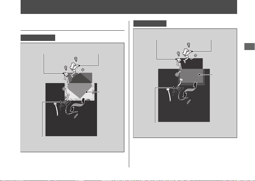
Removing & Installing Body Components
Battery
CBR1000RR/RA
CBR1000S1/S2
20170830152249_31MKF6100_enu_BOOK Page 140 Wednesday, August 30 2017 15:45:50 JST
Maintenance
137
Continued
Rubber strap
Positive terminal
Negative terminal
Battery
Rubber strap
Positive terminal
Negative terminal
Battery

#
Removal
Make sure the ignition switch is in the OFF
position.
1.
Remove the front seat. 2 P. 139
2.
Unhook the rubber strap from left side.
3.
Disconnect the negative - terminal from
the battery.
4.
Disconnect the positive + terminal from
the battery.
5.
Remove the battery taking care not to
drop the terminal nuts.
#
Installation
Install the parts in the reverse order of
removal. Always connect the positive +
terminal first. Make sure that bolts and nuts
are tight.
Make sure the clock information is correct
after the battery is reconnected. 2 P. 70
For proper handling of the battery, see
“Maintenance Fundamentals.” 2 P. 123
“Battery Goes Dead.” 2 P. 193
20170830152249_31MKF6100_enu_BOOK Page 141 Wednesday, August 30 2017 15:45:50 JST
Removing & Installing Body Components u Battery
Maintenance
138
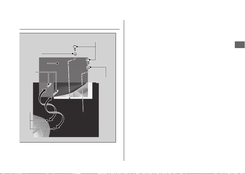
Front Seat
#
Removal
1.
Remove the mounting bolts and washers,
and then pull the front seat back and up.
#
Installation
1.
Install the front seat while inserting the
tabs into the recesses.
2.
Install the washers and mounting bolts.
3.
Tighten the mounting bolts securely.
Make sure that the seat is locked securely
in position by pulling it up lightly.
20170830152249_31MKF6100_enu_BOOK Page 142 Wednesday, August 30 2017 15:45:50 JST
Removing & Installing Body Components u Front Seat
Maintenance
139
Tabs
Front seat
Recesses
Mounting bolts
Washer
Washer
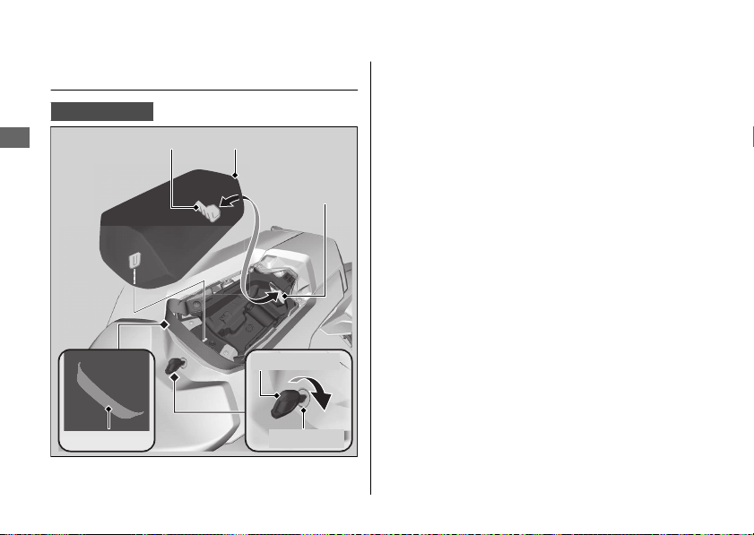
Rear Seat
CBR1000RR/RA
#
Removal
1.
Move the seat strap forward.
2.
Insert the ignition key into the seat lock.
3.
Turn the ignition key clockwise, then pull
the rear seat forward and up.
#
Installation
1.
Insert the tab into the recess.
2.
Push down on the front of the rear seat.
Make sure that the seat is locked securely
in position by pulling it up lightly.
3.
Move the seat strap to its original
position.
The seat locks automatically when closed.
Take care not to lock your key in the
compartment under the rear seat.
20170830152249_31MKF6100_enu_BOOK Page 143 Wednesday, August 30 2017 15:45:50 JST
Removing & Installing Body Components u Rear Seat
Maintenance
140
Rear seat
Seat lock
Ignition key
Tab
Recess
Seat strap
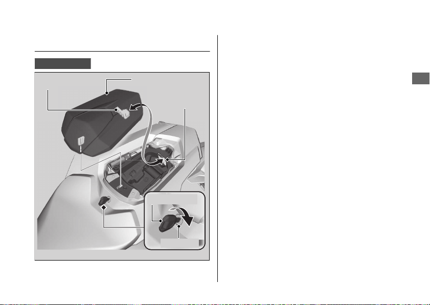
Single Seat Cowl
CBR1000S1/S2
#
Removal
1.
Insert the ignition key into the seat lock.
2.
Turn the ignition key clockwise, then pull
the single seat cowl forward and up.
#
Installation
1.
Insert the tab into the recess.
2.
Push down on the front of the single seat
cowl.
Make sure that the single seat cowl is
locked securely in position by pulling it up
lightly.
The single seat cowl locks automatically when
closed.
Take care not to lock your key in the
compartment under the single seat cowl.
20170830152249_31MKF6100_enu_BOOK Page 144 Wednesday, August 30 2017 15:45:50 JST
Removing & Installing Body Components u Single Seat Cowl
Maintenance
141
Single seat cowl
Tab
Recess
Ignition key
Seat lock
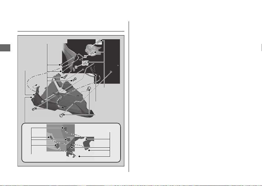
Under Cowl
#
Removal
1.
Remove the pan screws and under cowl
bolts.
2.
Remove the under cowl carefully by
releasing the guides from the hooks of
the middle cowl side as shown in the
illustration.
#
Installation
1.
Install the under cowl using reverse of the
removal procedure.
2.
Route the tubes through the opening of
the lower cowl.
3.
Install and tighten the under cowl bolts
securely.
4.
Install and tighten the pan screws
securely.
20170830152249_31MKF6100_enu_BOOK Page 145 Wednesday, August 30 2017 15:45:50 JST
Removing & Installing Body Components u Under Cowl
Maintenance
142
Pan
screws
Under
cowl bolts
Hooks
Under
cowl
Guides
Tubes
Under cowl bolts
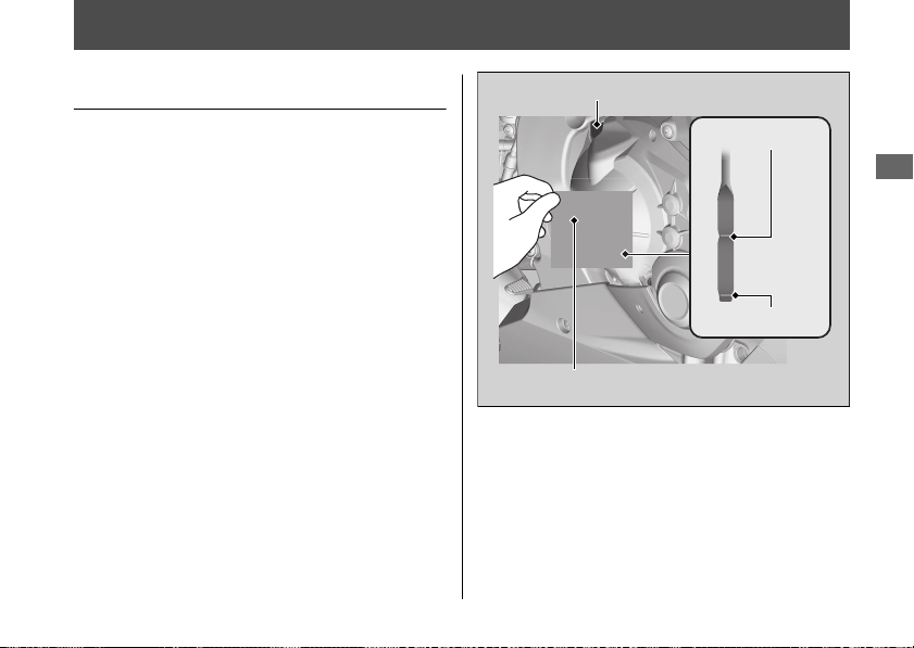
Engine Oil
Checking the Engine Oil
1.
If the engine is cold, idle the engine for 3
to 5 minutes.
2.
Turn the ignition switch to the OFF
position and wait for 2 to 3 minutes.
3.
Place your motorcycle in an upright
position on a firm, level surface.
4.
Remove the dipstick and wipe it clean.
5.
Insert the dipstick until it seats, but don't
screw it in.
6.
Check that the oil level is between the
upper level and lower level marks on the
dipstick.
7.
Securely install the dipstick.
20170830152249_31MKF6100_enu_BOOK Page 146 Wednesday, August 30 2017 15:45:50 JST
Maintenance
143
Oil fill cap
Upper level
Lower level
Dipstick
Adding Engine Oil
If the engine oil is below or near the lower
level mark, add the recommended engine oil.
2 P. 129, 2 P. 224
1.
Remove the oil fill cap. Add the
recommended oil until it reaches the
upper level mark.
u Place your motorcycle in an upright
position on a firm, level surface when
checking the oil level.
u Do not overfill above the upper level
mark.
u Make sure no foreign objects enter the
oil filler opening.
u Wipe up any spills immediately.
2.
Securely reinstall the oil fill cap.
NOTICE
Overfilling with oil or operating with insufficient
oil can cause damage to your engine. Do not mix
different brands and grades of oil. They may
affect lubrication and clutch operation.
For the recommended oil and oil selection
guidelines, see “Maintenance Fundamentals.”
2 P. 129
20170830152249_31MKF6100_enu_BOOK Page 147 Wednesday, August 30 2017 15:45:50 JST
Engine Oil u Adding Engine Oil
Maintenance
144
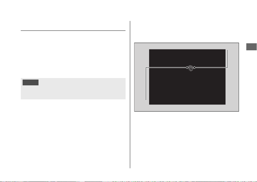
Changing Engine Oil & Filter
Changing the oil and filter requires special
tools. We recommend that you have your
motorcycle serviced by your dealer.
Use a new Honda Genuine oil filter or
equivalent specified for your model.
NOTICE
Using the wrong oil filter can result in serious
damage to the engine.
1.
Remove the under cowl. 2 P. 142
2.
If the engine is cold, idle the engine for 3
to 5 minutes.
3.
Turn the ignition switch to the OFF
position and wait for 2 to 3 minutes.
4.
Place your motorcycle on a firm, level
surface.
5.
Place a drain pan under the drain bolt.
6.
Remove the oil fill cap, drain bolt, and
sealing washer to drain the oil.
20170830152249_31MKF6100_enu_BOOK Page 148 Wednesday, August 30 2017 15:45:50 JST
Engine Oil u Changing Engine Oil & Filter
Maintenance
145
Continued
Sealing washer
Drain bolt
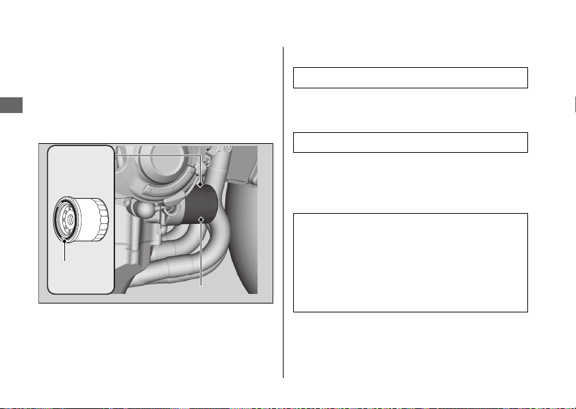
7.
Remove the oil filter with a filter wrench
and let the remaining oil drain out. Make
sure the prior seal is not stuck to the
engine.
u Discard the oil and oil filter at an
approved recycling center.
8.
Apply a thin coat of engine oil to the
rubber seal of a new oil filter.
9.
Install the new oil filter and tighten.
Torque: 19 lbf·ft (26 N·m, 2.7 kgf·m)
10.
Install a new sealing washer onto the
drain bolt. Tighten the drain bolt.
Torque: 22 lbf·ft (30 N·m, 3.1 kgf·m)
11.
Fill the crankcase with the recommended
oil (2 P. 129, 2 P. 224) and install the oil fill
cap.
Required oil
When changing oil & engine oil
filter:
2.9 US qt (2.7 L)
When changing oil only:
2.6 US qt (2.5 L)
12.
Check the oil level. 2 P. 143
13.
Check that there are no oil leaks.
14.
Install the under cowl. 2 P. 142
20170830152249_31MKF6100_enu_BOOK Page 149 Wednesday, August 30 2017 15:45:50 JST
Engine Oil u Changing Engine Oil & Filter
Maintenance
146
Rubber
seal
Oil filter
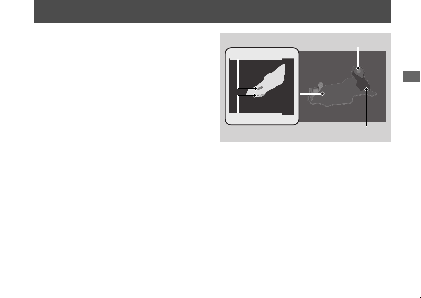
Coolant
Checking the Coolant
Check the coolant level in the reserve tank
while the engine is cold.
1.
Place your motorcycle on a firm, level
surface.
2.
Hold your motorcycle in an upright
position.
3.
Check that the coolant level is between
the UPPER level and LOWER level marks
on the reserve tank.
If the coolant level is dropping noticeably or
the reserve tank is empty, you likely have a
serious leak. Have your motorcycle inspected
by your dealer.
20170830152249_31MKF6100_enu_BOOK Page 150 Wednesday, August 30 2017 15:45:50 JST
Maintenance
147
UPPER level
LOWER level
Reserve tank
Reserve tank cap
Adding Coolant
If the coolant level is below the LOWER level
mark, add the recommended coolant
(2 P. 132) until the level reaches the UPPER
level mark.
Add fluid only from the reserve tank cap and
do not remove the radiator cap.
1.
Remove the reserve tank cap and add
fluid while monitoring the coolant level.
u Do not overfill above the UPPER level
mark.
u Make sure no foreign objects enter the
reserve tank opening.
2.
Securely reinstall the reserve tank cap.
3WARNING
Removing the radiator cap while the
engine is hot can cause the coolant to
spray out, potentially scalding you.
Always let the engine and radiator cool
down before removing the radiator cap.
Changing Coolant
Have your dealer change the coolant unless
you have the proper tools and are
mechanically qualified.
20170830152249_31MKF6100_enu_BOOK Page 151 Wednesday, August 30 2017 15:45:50 JST
Coolant u Adding Coolant
Maintenance
148
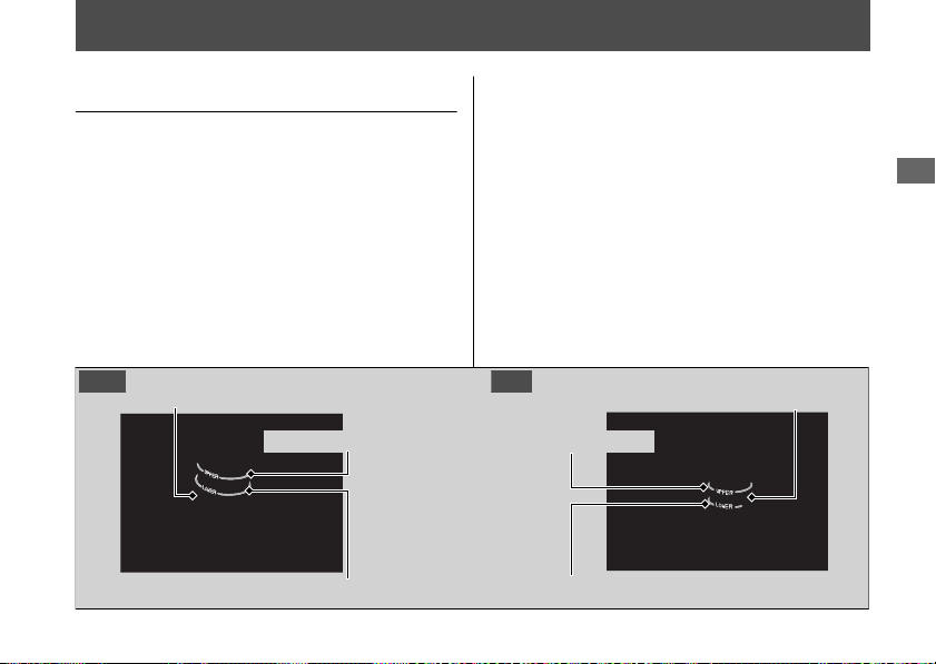
Brakes
Checking Brake Fluid
1.
Place your motorcycle in an upright
position on a firm, level surface.
2.
Check that the brake fluid reservoir is
horizontal and that the fluid level is
between the LOWER level and UPPER
level marks.
If the brake fluid level in either reservoir is
below the LOWER level mark or the brake
lever and pedal freeplay becomes excessive,
inspect the brake pads for wear.
If the brake pads are not worn, you most
likely have a leak. Have your motorcycle
inspected by your dealer.
20170830152249_31MKF6100_enu_BOOK Page 152 Wednesday, August 30 2017 15:45:50 JST
Maintenance
149
Front brake fluid reservoir
UPPER level mark
LOWER level mark
Rear brake fluid reservoir
Front Rear
LOWER level mark
UPPER level mark
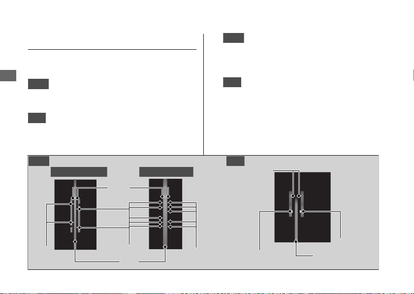
Inspecting the Brake Pads
Check the condition of the brake pad wear
indicators.
Front
The pads need to be replaced if a
brake pad is worn to the bottom of the
indicator.
Rear
The pads need to be replaced if a brake
pad is worn to the indicator.
1.
Front
Inspect the brake pads from in front
of the brake caliper.
u Always inspect both left and right
brake calipers.
2.
Rear
Inspect the brake pads from the rear
right of the motorcycle.
If necessary have the pads replaced by your
dealer.
Always replace both left and right brake pads
at the same time.
20170830152249_31MKF6100_enu_BOOK Page 153 Wednesday, August 30 2017 15:45:50 JST
Brakes u Inspecting the Brake Pads
Maintenance
150
Front Rear
Pads
Disc
Wear
indicator
Pads
Wear indicator
Disc
Wear indicator
Wear indicator
CBR1000RR/RA CBR1000S1/S2
Wear
indicator
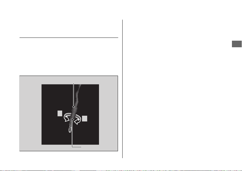
Adjusting the Brake Light
Switch
Check the operation of the brake light switch.
Hold the brake light switch and turn the
adjusting nut in the direction A if the switch
operates too late, or turn the nut in the
direction B if the switch operates too soon.
20170830152249_31MKF6100_enu_BOOK Page 154 Wednesday, August 30 2017 15:45:50 JST
Brakes u Adjusting the Brake Light Switch
Maintenance
151
Brake light switch
Adjusting nut
B
A
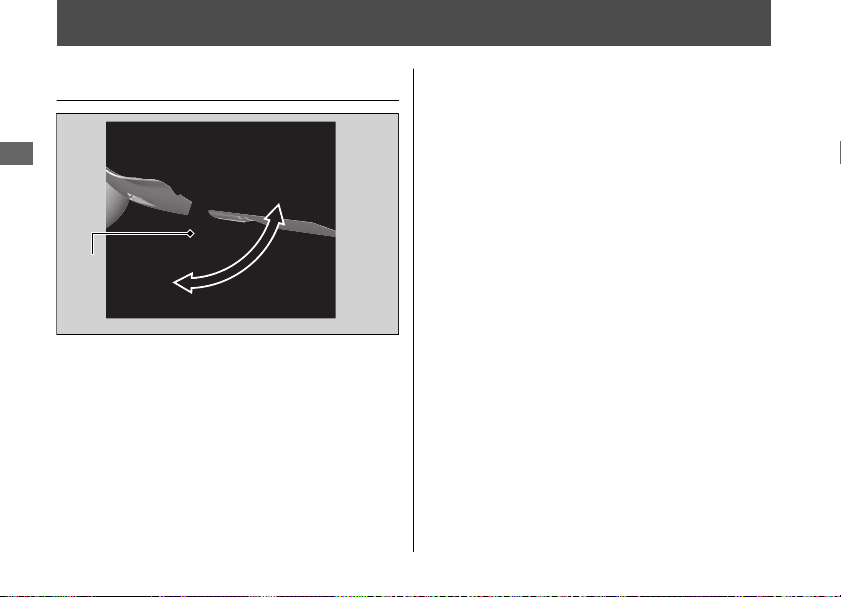
Side Stand
Checking the Side Stand
1.
Check that the side stand operates
smoothly. If the side stand is stiff or
squeaky, clean the pivot area and
lubricate the pivot bolt with clean grease.
2.
Check the spring for damage or loss of
tension.
3.
Sit on the motorcycle, shift the
transmission to Neutral, and raise the side
stand.
4.
Start the engine, pull the clutch lever in,
and shift the transmission into gear.
5.
Lower the side stand all the way. The
engine should stop as you lower the side
stand. If the engine doesn't stop, have
your motorcycle inspected by your dealer.
20170830152249_31MKF6100_enu_BOOK Page 155 Wednesday, August 30 2017 15:45:50 JST
Maintenance
152
Side stand
spring
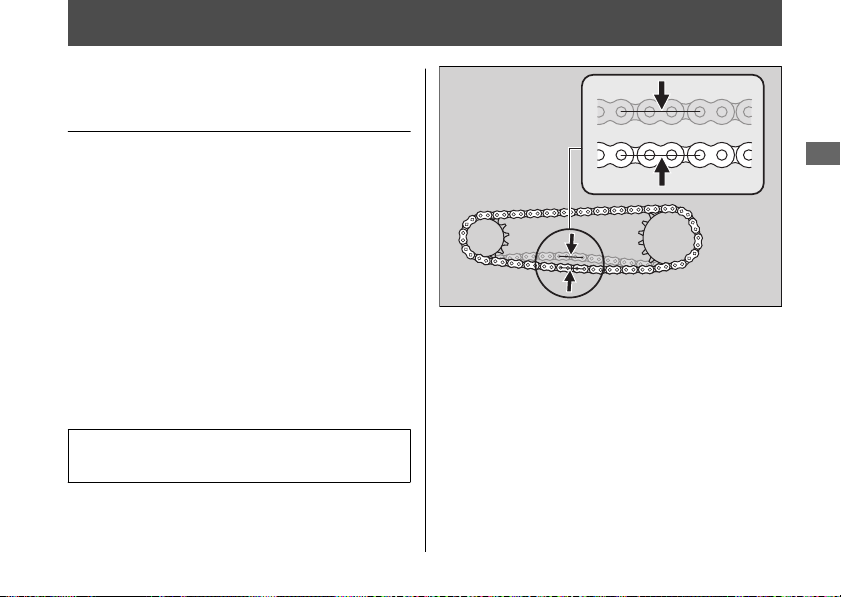
Drive Chain
Inspecting the Drive Chain
Slack
Check the drive chain slack at several points
along the chain. If the slack is not constant at
all points, some links may be kinked and
binding.
Have the chain inspected by your dealer.
1.
Shift the transmission to Neutral. Stop the
engine.
2.
Place your motorcycle on its side stand on
a firm, level surface.
3.
Check the slack in the lower half of the
drive chain midway between the
sprockets.
Drive chain slack:
1.0 - 1.4 in (25 - 35 mm)
u Do not ride your motorcycle if the
slack exceeds 2.0 in (50 mm).
4.
Roll the motorcycle forward and check
that the chain moves smoothly.
5.
Inspect the sprockets. 2 P. 131
6.
Clean and lubricate the drive chain.
2 P. 131
20170830152249_31MKF6100_enu_BOOK Page 156 Wednesday, August 30 2017 15:45:50 JST
Maintenance
153
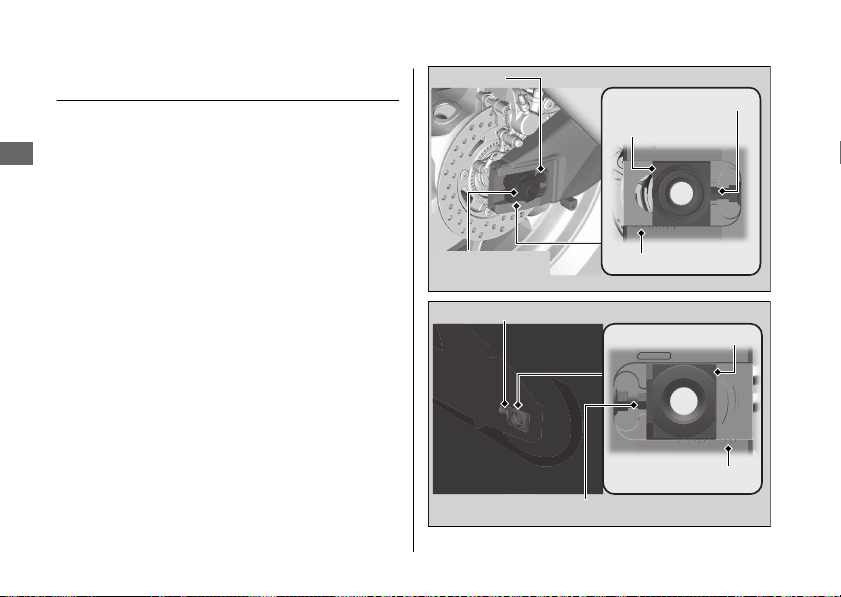
Adjusting the Drive Chain Slack
Adjusting the chain requires special tools.
Have the drive chain slack adjusted by your
dealer.
When adjusting the drive chain slack, be
careful not to damage the wheel speed
sensor and pulser ring.
1.
Shift the transmission to Neutral. Stop the
engine.
2.
Place your motorcycle on its side stand on
a firm, level surface.
3.
Loosen the rear axle nut.
4.
Loosen the lock nuts on both adjusting
bolts.
20170830152249_31MKF6100_enu_BOOK Page 157 Wednesday, August 30 2017 15:45:50 JST
Drive Chain u Adjusting the Drive Chain Slack
Maintenance
154
Lock nut
Adjusting bolt
Rear axle nut/
washer
Adjusting plate
Scale graduations
Adjusting plate
Scale graduations
Lock nut
Adjusting bolt
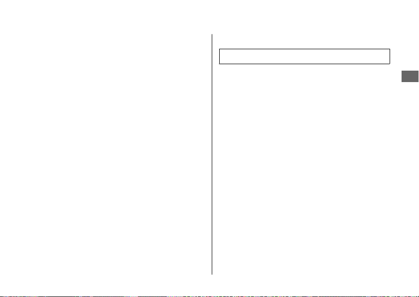
5.
Turn both adjusting bolts an equal
number of turns until the correct drive
chain slack is obtained. Turn the adjusting
bolts counterclockwise to tighten the
chain. Turn the adjusting bolts clockwise
and push the rear wheel toward the front
to provide more slack.
Adjust the slack at a point midway
between the front sprocket and the rear
wheel sprocket.
Check the drive chain slack. 2 P. 153
6.
Check rear axle alignment by making sure
the end of the chain adjusting plate aligns
with the scale graduations on both sides
of the swingarm.
Both marks should correspond. If the axle
is misaligned, turn the right or left
adjusting bolt until the marks are aligned
and recheck chain slack.
7.
Tighten the rear axle nut.
Torque: 100 lbf·ft (135 N·m, 13.8 kgf·m)
8.
Hold the adjusting bolts and tighten the
lock nuts.
9.
Recheck drive chain slack.
If a torque wrench was not used for
installation, see your dealer as soon as
possible to verify proper assembly.
Improper assembly may lead to loss of
braking capacity.
20170830152249_31MKF6100_enu_BOOK Page 158 Wednesday, August 30 2017 15:45:50 JST
Drive Chain u Adjusting the Drive Chain Slack
Maintenance
155
Continued

#
Checking the Drive Chain Wear
Check the chain wear label when adjusting
the drive chain. If the front edge of the
adjusting plate enters the red zone on the
label after the chain has been adjusted to the
proper slack, the chain is excessively worn
and must be replaced.
Chain: RK525ROZ7
If necessary have the drive chain replaced by
your dealer.
20170830152249_31MKF6100_enu_BOOK Page 159 Wednesday, August 30 2017 15:45:50 JST
Drive Chain u Adjusting the Drive Chain Slack
Maintenance
156
Adjusting plate
Red zone
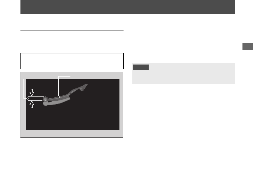
Clutch
Checking the Clutch
#
Checking the Clutch Lever Freeplay
Check the clutch lever freeplay.
Freeplay at the clutch lever:
0.4 - 0.8 in (10 - 20 mm)
Check the clutch cable for kinks or signs of
wear. If necessary have it replaced by your
dealer.
Lubricate the clutch cable with a
commercially available cable lubricant to
prevent premature wear and corrosion.
NOTICE
Improper freeplay adjustment can cause
premature clutch wear.
20170830152249_31MKF6100_enu_BOOK Page 160 Wednesday, August 30 2017 15:45:50 JST
Maintenance
157
Clutch lever
Freeplay
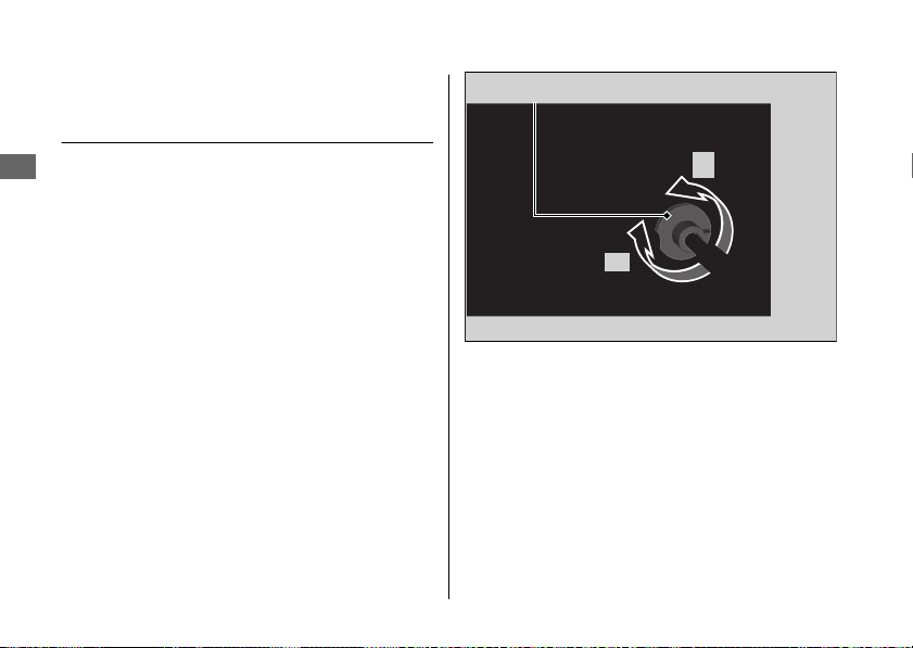
Adjusting the Clutch Lever
Freeplay
#
Upper Adjustment
Attempt adjustment with the upper clutch
cable adjuster first.
Turn the clutch cable adjuster until the
freeplay is 0.4 - 0.8 in (10 - 20 mm).
20170830152249_31MKF6100_enu_BOOK Page 161 Wednesday, August 30 2017 15:45:50 JST
Clutch u Adjusting the Clutch Lever Freeplay
Maintenance
158
Upper clutch cable adjuster
+
-
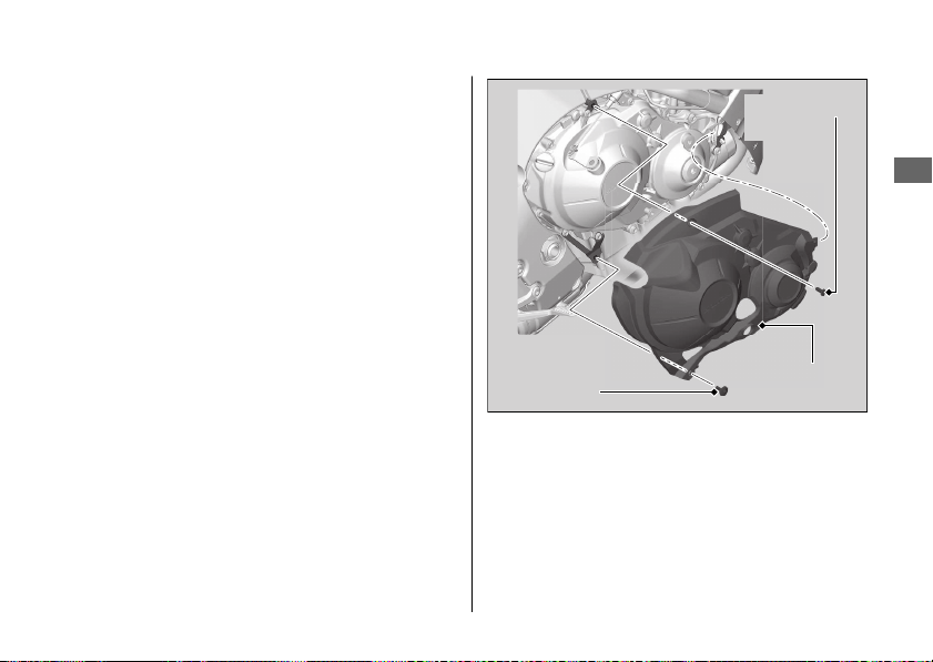
#
Lower Adjustment
If the upper clutch cable adjuster is threaded
out near its limit, or the correct freeplay
cannot be obtained, attempt adjustment with
the lower clutch cable adjusting nut.
1.
Turn the upper clutch cable adjuster all
the way in (to provide maximum freeplay).
2.
Remove the under cowl. 2 P. 142
3.
Remove the pan screw and under cowl
bolt.
4.
Remove the rear under cover.
20170830152249_31MKF6100_enu_BOOK Page 162 Wednesday, August 30 2017 15:45:50 JST
Clutch u Adjusting the Clutch Lever Freeplay
Maintenance
159
Continued
Pan screw
Under cowl
bolt
Rear under
cover
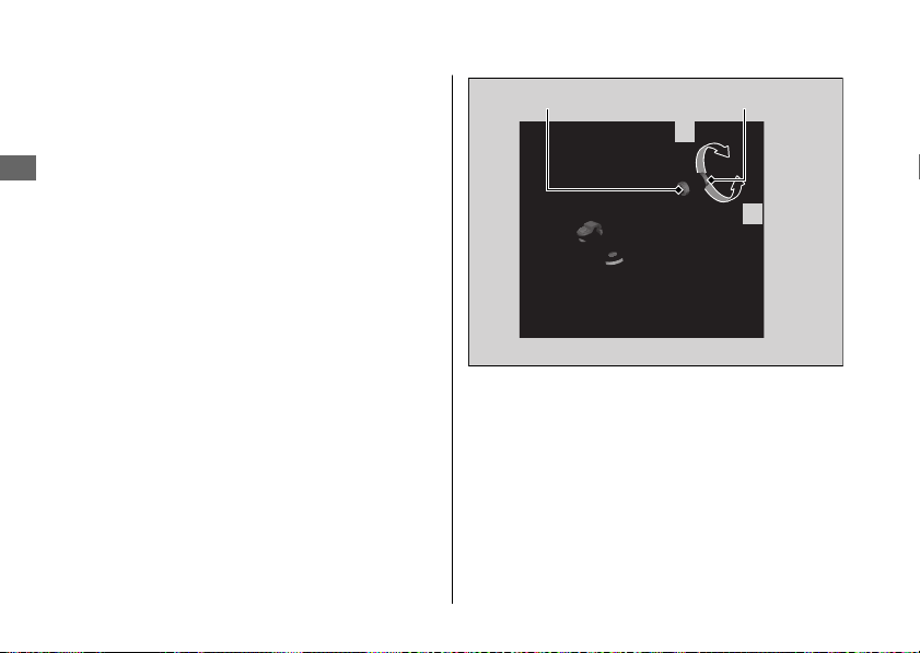
5.
Loosen the lower lock nut.
6.
Turn the adjusting nut until the clutch
lever freeplay is 0.4 - 0.8 in (10 - 20 mm).
7.
Tighten the lower lock nut and check the
clutch lever freeplay.
8.
Install the rear under cover using reverse
of the removal procedure.
9.
Install and tighten the under cowl bolt
and pan screw securely.
10.
Install the under cowl. 2 P. 142
11.
Start the engine, pull the clutch lever in,
and shift into gear. Make sure the engine
does not stall and the motorcycle does
not creep. Gradually release the clutch
lever and open the throttle. Your
motorcycle should move smoothly and
accelerate gradually.
If proper adjustment cannot be obtained or
the clutch does not work correctly, see your
dealer.
20170830152249_31MKF6100_enu_BOOK Page 163 Wednesday, August 30 2017 15:45:50 JST
Clutch u Adjusting the Clutch Lever Freeplay
Maintenance
160
Lower lock nut Adjusting nut
+
–
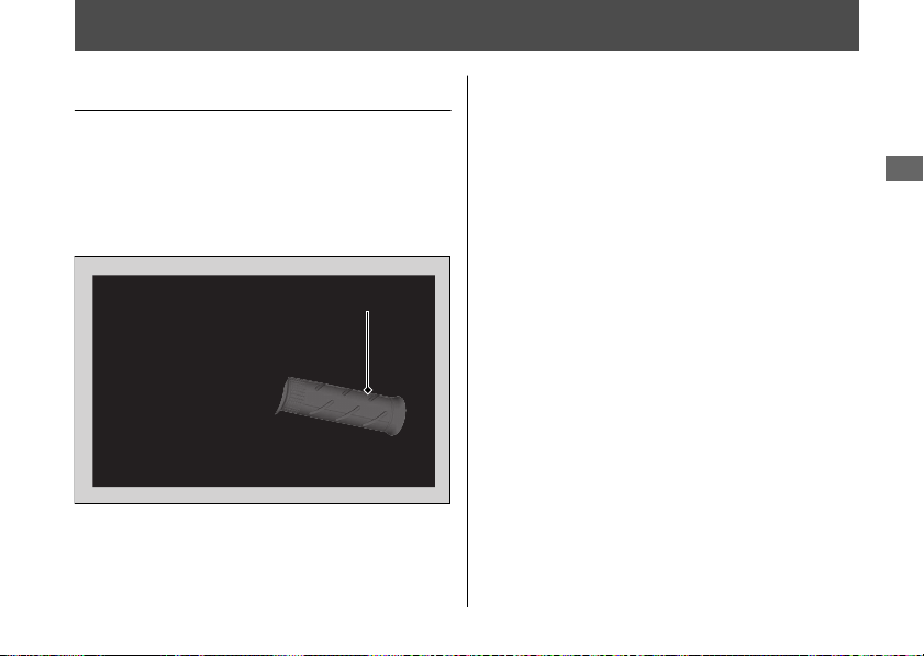
Throttle
Checking the Throttle
With the engine off, check that the throttle
rotates smoothly from fully closed to fully
open. If the throttle does not move smoothly,
close automatically, have the motorcycle
inspected by your dealer.
20170830152249_31MKF6100_enu_BOOK Page 164 Wednesday, August 30 2017 15:45:50 JST
Maintenance
161
Throttle
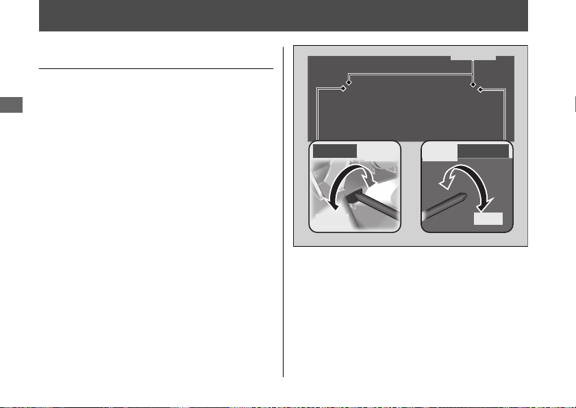
Other Adjustments
Adjusting the Headlight Aim
You can adjust vertical aim of the headlight
for proper alignment. Turn the screw in or
out as necessary using a Phillips screwdriver.
Obey local laws and regulations.
20170830152249_31MKF6100_enu_BOOK Page 165 Wednesday, August 30 2017 15:45:50 JST
Maintenance
162
Raise
Lower
Left side Right side
Raise
Lower
Screws
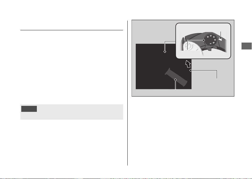
Adjusting the Brake Lever
You can adjust the distance between the tip
of the brake lever and handle grip.
#
Adjustment method
Turn the adjuster until the numbers align with
the index mark while pushing the lever
forward in the desired position.
After adjustment, check that the lever
operates correctly before riding.
NOTICE
Do not turn the adjuster beyond its natural limit.
20170830152249_31MKF6100_enu_BOOK Page 166 Wednesday, August 30 2017 15:45:50 JST
Other Adjustments u Adjusting the Brake Lever
Maintenance
163
Index mark
Adjuster
Forward
Brake lever
Handle grip
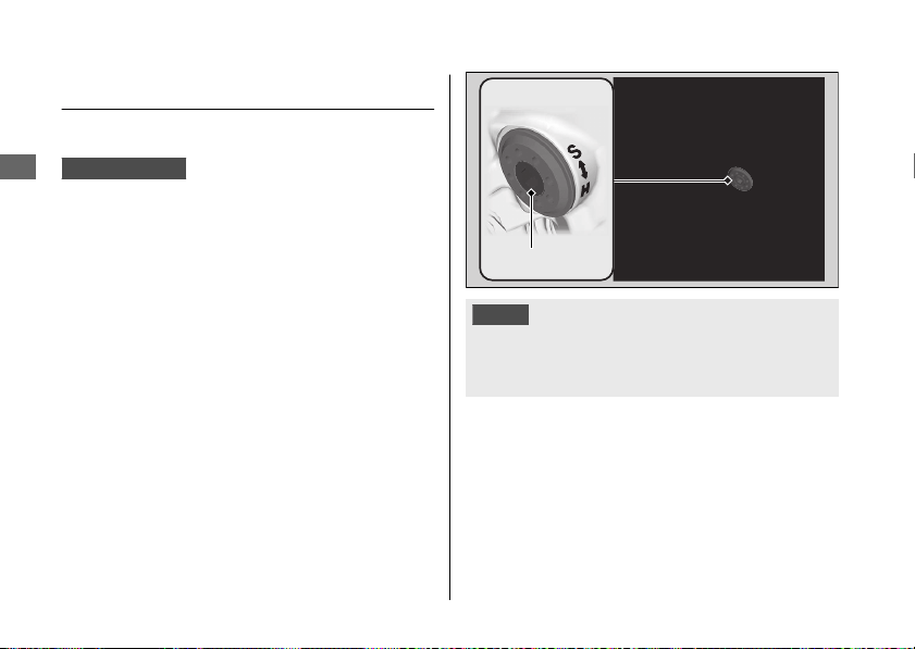
Adjusting the Front Suspension
#
Spring Preload
CBR1000RR/RA
You can adjust the spring preload by the
adjuster to suit the load or the road surface.
The spring preload adjuster has 15 turns.
Turn clockwise to increase spring preload
(hard), or turn counterclockwise to decrease
spring preload (soft). The standard position is
7 1/2 turns from the full soft position.
NOTICE
Do not turn the adjuster beyond its limits.
Adjust both left and right forks to the same
spring preload.
20170830152249_31MKF6100_enu_BOOK Page 167 Wednesday, August 30 2017 15:45:50 JST
Other Adjustments u Adjusting the Front Suspension
Maintenance
164
Adjuster
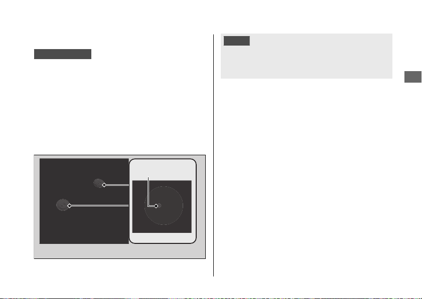
#
Rebound Damping
CBR1000RR/RA
You can adjust the rebound damping by the
TEN adjuster to suit the load or the road
surface.
The TEN adjuster has 5 1/2 turns.
Turn clockwise to increase rebound damping
(hard), or turn counterclockwise to decrease
rebound damping (soft). The standard
position is 4 turns from the full hard position.
NOTICE
Do not turn the adjuster beyond its limits.
Adjust both left and right forks to the same
rebound damping.
20170830152249_31MKF6100_enu_BOOK Page 168 Wednesday, August 30 2017 15:45:50 JST
Other Adjustments u Adjusting the Front Suspension
Maintenance
165
Continued
TEN adjuster
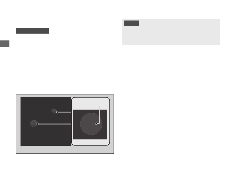
#
Compression Damping
CBR1000RR/RA
You can adjust the compression damping by
the COM adjuster to suit the load or the road
surface.
The COM adjuster has 7 turns.
Turn clockwise to increase compression
damping (hard), or turn counterclockwise to
decrease compression damping (soft). The
standard position is 5 turns from the full hard
position.
NOTICE
Do not turn the adjuster beyond its limits.
Adjust both left and right forks to the same
compression damping.
20170830152249_31MKF6100_enu_BOOK Page 169 Wednesday, August 30 2017 15:45:50 JST
Other Adjustments u Adjusting the Front Suspension
Maintenance
166
COM adjuster
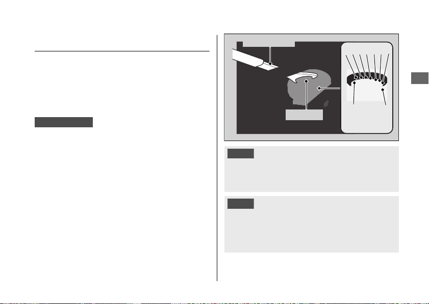
Adjusting the Rear Suspension
Adjusting the suspension requires a pin
spanner. We recommend that you have your
motorcycle serviced by your dealer.
#
Spring Preload
CBR1000RR/RA
You can adjust the spring preload by the
adjuster to suit the load or the road surface.
Turn the adjuster using the pin spanner.
The preload adjuster has 9 positions.
Positions 1 to 3 are for a decrease spring
preload (soft), or turn the position 5 to 9
increase spring preload (hard). The standard
position is 4.
NOTICE
Do not turn the adjuster beyond its limits.
Attempting to adjust directly from 1 to 9 or 9 to 1
may damage the shock absorber.
NOTICE
The rear shock absorber damper unit contains
high pressure nitrogen gas. Do not attempt to
disassemble, service, or improperly dispose of
the damper. See your dealer.
20170830152249_31MKF6100_enu_BOOK Page 170 Wednesday, August 30 2017 15:45:50 JST
Other Adjustments u Adjusting the Rear Suspension
Maintenance
167
Continued
1
2 3 4 5 6 7 8
9
Pin spanner
Adjuster
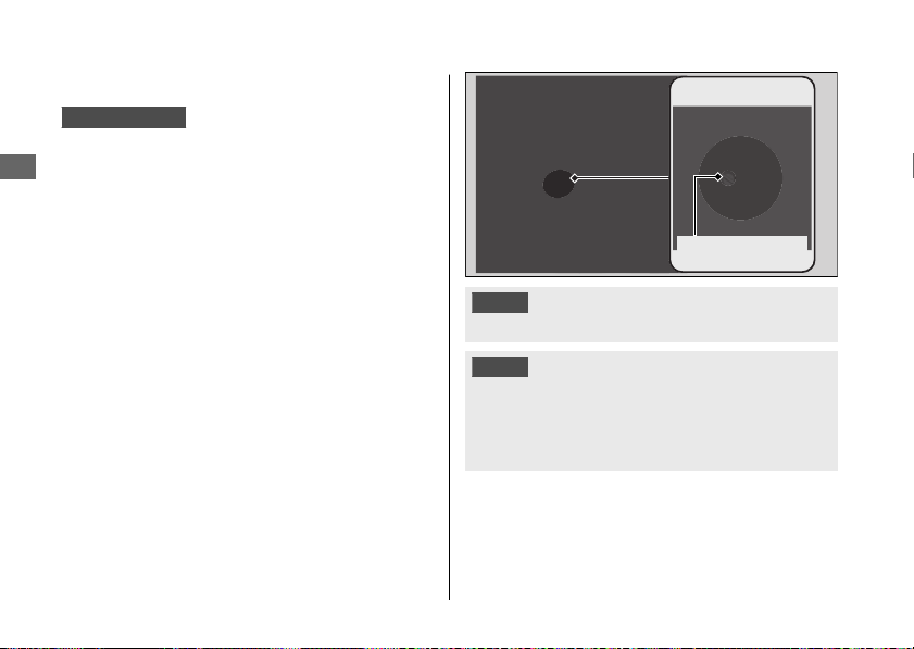
#
Rebound Damping
CBR1000RR/RA
You can adjust the rebound damping by the
TEN adjuster to suit the load or the road
surface.
The TEN adjuster has 4 turns.
Turn clockwise to increase rebound damping
(hard), or turn counterclockwise to decrease
rebound damping (soft).
The standard position is 2 1/2 turns from the
full hard position.
NOTICE
Do not turn the adjuster beyond its limits.
NOTICE
The rear shock absorber damper unit contains
high pressure nitrogen gas. Do not attempt to
disassemble, service, or improperly dispose of
the damper. See your dealer.
20170830152249_31MKF6100_enu_BOOK Page 171 Wednesday, August 30 2017 15:45:50 JST
Other Adjustments u Adjusting the Rear Suspension
Maintenance
168
TEN adjuster
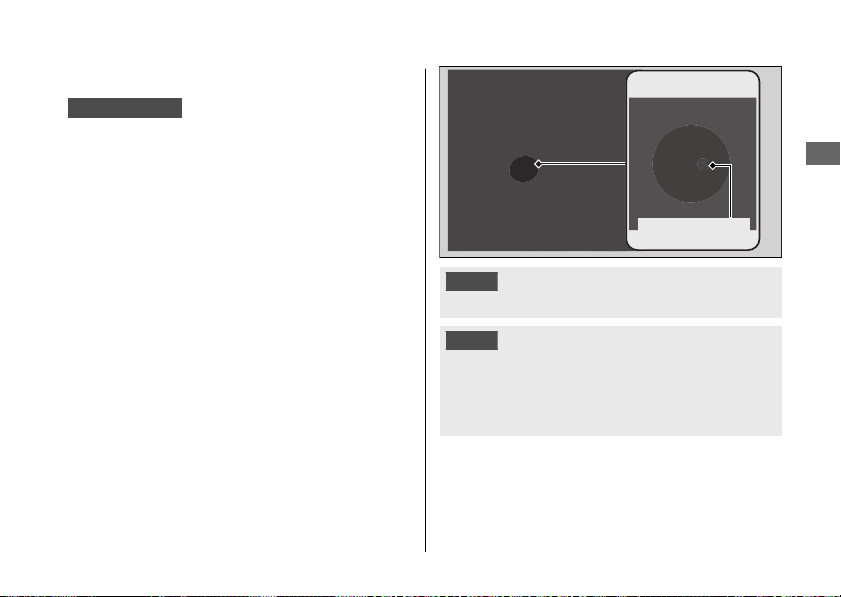
#
Compression Damping
CBR1000RR/RA
You can adjust the compression damping by
the COM adjuster to suit the load or the road
surface.
The COM adjuster has 4 1/2 turns.
Turn clockwise to increase compression
damping (hard), or turn counterclockwise to
decrease compression damping (soft).
The standard position is 3 turns from the full
hard position.
NOTICE
Do not turn the adjuster beyond its limits.
NOTICE
The rear shock absorber damper unit contains
high pressure nitrogen gas. Do not attempt to
disassemble, service, or improperly dispose of
the damper. See your dealer.
20170830152249_31MKF6100_enu_BOOK Page 172 Wednesday, August 30 2017 15:45:50 JST
Other Adjustments u Adjusting the Rear Suspension
Maintenance
169
COM adjuster

Adjusting the ÖHLINS Smart EC
System
CBR1000S1/S2
This model is equipped with the ÖHLINS
Smart EC system.
This system consists of front and rear
suspension and Suspension Control Unit
(SCU).
This system provides pre-programmed
damping characteristics optimized for
different situation for the front and rear
suspension.
The front and rear suspension constantly
determine riding conditions as the SCU
receives signals from the different control
units on the motorcycle. As a result, the
optimum rebound and compression
damping force for road are provided.
The system continually adjusts compression
and rebound damping levels according to
the situation.
You can adjusts the front and rear
suspension preload manually.
ÖHLINS Smart EC is a trademark of ÖHLINS RACING AB, Sweden.
20170830152249_31MKF6100_enu_BOOK Page 173 Wednesday, August 30 2017 15:45:50 JST
Other Adjustments u Adjusting the ÖHLINS Smart EC System
Maintenance
170
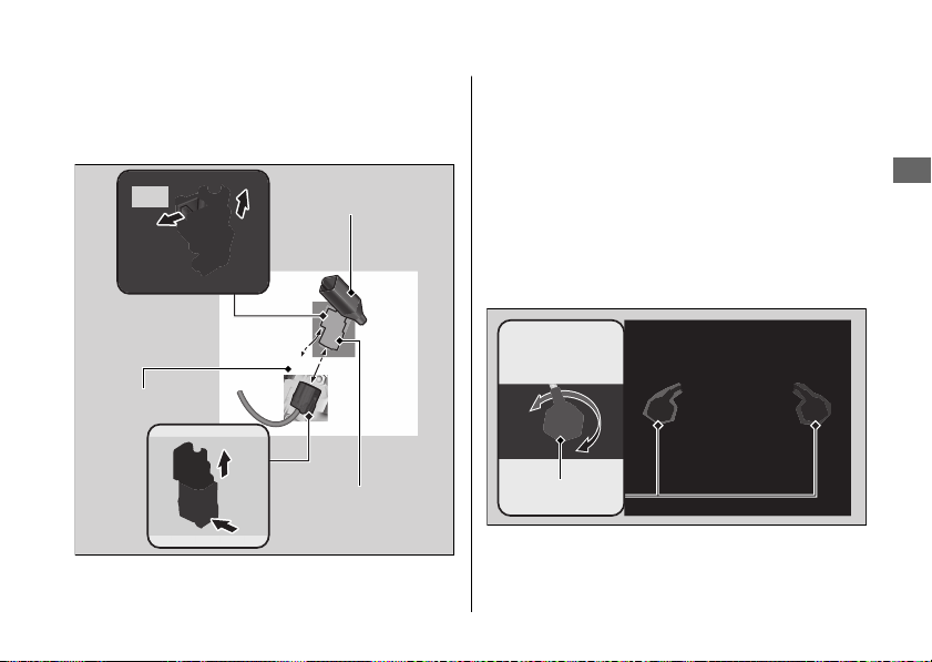
#
Front Spring Preload
You can adjust the spring preload by the
adjuster to suit the load or the road surface.
1.
Make sure the ignition switch is in the OFF
position. 2 P. 99
2.
Slide the connector cover, and then
disconnect the front suspension
connector from the coupler clip.
3.
Disconnect the front suspension
connector.
u Do not remove by pulling on the wire
harness.
20170830152249_31MKF6100_enu_BOOK Page 174 Wednesday, August 30 2017 15:45:50 JST
Other Adjustments u Adjusting the ÖHLINS Smart EC System
Maintenance
171
Continued
Pull
Coupler clip
Push
Connector cover
Front suspension
connector
Adjusters

4.
Turn clockwise to increase spring preload
(hard), or turn counterclockwise to
decrease spring preload (soft).
The standard position is the 4 turns from
the full soft position.
NOTICE
Do not turn the adjuster beyond its limits.
Adjust both left and right forks to the same
spring preload.
5.
After the adjustment, connect the front
suspension connector.
u Be careful not to allow water or dust to
enter the connector.
u Make sure to install the connector
completely.
6.
Connect the front suspension connector
to the coupler clip and then install the
connector cover.
20170830152249_31MKF6100_enu_BOOK Page 175 Wednesday, August 30 2017 15:45:50 JST
Other Adjustments u Adjusting the ÖHLINS Smart EC System
Maintenance
172
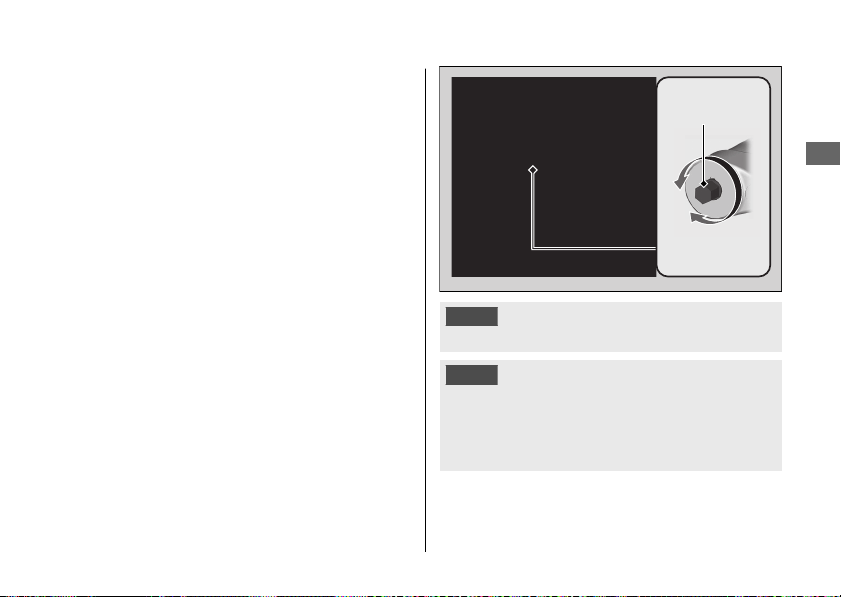
#
Rear Spring Preload
You can adjust the spring preload by the
adjuster knob to suit the load or the road
surface.
Turn clockwise to increase spring preload
(hard), or turn counterclockwise to decrease
spring preload (soft).
The standard position is 8 turns from the full
hard position.
NOTICE
Do not turn the adjuster beyond its limits.
NOTICE
The rear shock absorber damper unit contains
high pressure nitrogen gas. Do not attempt to
disassemble, service, or improperly dispose of
the damper. See your dealer.
20170830152249_31MKF6100_enu_BOOK Page 176 Wednesday, August 30 2017 15:45:50 JST
Other Adjustments u Adjusting the ÖHLINS Smart EC System
Maintenance
173
Continued
S
H
Adjuster
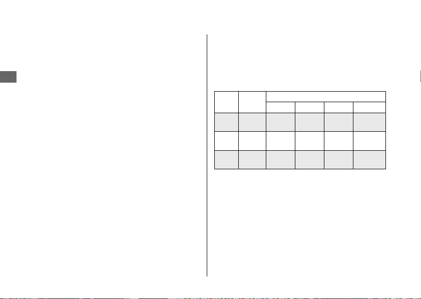
#
Damping Adjustment
You can select A-mode which automatically
adjusts damping according to the riding
situation and MANUAL mode which allows
damping level to be set manually.
A-mode
A-mode will automatically adjust
compression and rebound damping levels
individually for the front fork and rear
suspension to provide desired change in
behavior of the motorcycle.
A-mode provides 3 modes (A1, A2 and A3)
with different riding feel and ride
characteristics for various situations.
Defaults of A-mode can be adjusted using
the ÖHLINS Objective Based Tuning interface
(OBTi).
“OBTi” allows the rider to affect the
characteristics.
Adjustable OBTi support items and riding
situations for each A-mode are as follows.
A-
mode
Situation
OBTi support items
BRAKE ACC CORNER GENERAL
A1
track
riding
A A A A
A2
winding
roads
A N/A N/A A
A3
street
riding
A N/A N/A A
A : Adjustable
N/A : Not adjustable
20170830152249_31MKF6100_enu_BOOK Page 177 Wednesday, August 30 2017 15:45:50 JST
Other Adjustments u Adjusting the ÖHLINS Smart EC System
Maintenance
174
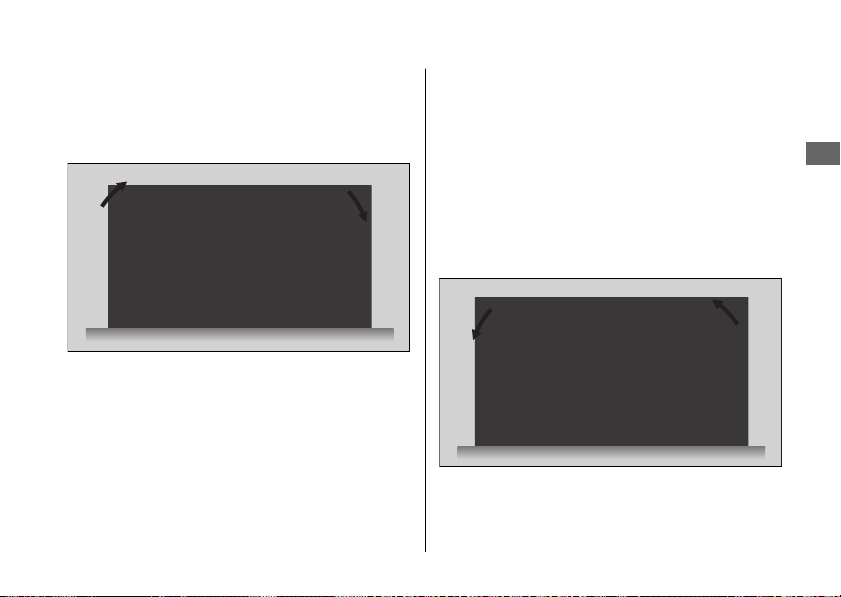
BRAKE:
By adjusting the brake support objective it is
possible to increase (+) or decrease (-) the
pitching resistance during initial braking.
ACC (A1 only):
By adjusting the acceleration objective it is
possible to increase (+) or decrease (-) the
pitching resistance during accelerating.
Direction
(+): Motorcycle feels more stable especially
during hard acceleration out of corner.
(-): Useful to increase weight transfer to
increase rear tire load.
20170830152249_31MKF6100_enu_BOOK Page 178 Wednesday, August 30 2017 15:45:50 JST
Other Adjustments u Adjusting the ÖHLINS Smart EC System
Maintenance
175
Continued

CORNER (A1 only):
By adjusting the corner objective it is possible
to increase (+) or decrease (-) the agile
movements of the while turning.
Direction
(+): More agility especially in middle of
corner.
(-): Good setting for rain or low grip
condition.
GENERAL:
By adjusting the firmness objective it is
possible to increase (+) or decrease (-) the
amount of overall damping levels.
Direction
For A1 mode
(+): Good for high grip tire and high road
surface temperature.
(-): Good setting for rain or low grip
condition.
For A2 and A3 mode
Tuning the objective more towards comfort.
To adjustment the “BRAKE”, “ACC
”,
“CORNER” and “GENERAL”. 2 P. 45
2 P. 51
To select the S mode. 2 P. 102
20170830152249_31MKF6100_enu_BOOK Page 179 Wednesday, August 30 2017 15:45:50 JST
Other Adjustments u Adjusting the ÖHLINS Smart EC System
Maintenance
176

MANUAL mode
The suspension setting can be fixed at a
certain value on compression and rebound
damping of the front and rear suspensions.
The damping of front and rear suspension
cannot be changed by riding behavior
automatically.
MANUAL mode provides 3 modes (M1, M2
and M3).
Preset of M1 is suitable for track riding.
Preset of M2 is suitable for winding roads.
Preset of M3 is suitable for street riding.
Each MANUAL mode allows the following
damping level to be adjusted as desired:
FR COM: Compression damping for front
suspension
FR REB: Rebound damping for front
suspension
RR COM: Compression damping for rear
suspension
RR REB: Rebound damping for rear
suspension
To adjustment the “FR
COM”, “FR REB”,
“RR COM” and “RR REB”. 2 P. 45 2 P. 52
To select the S mode. 2 P. 102
20170830152249_31MKF6100_enu_BOOK Page 180 Wednesday, August 30 2017 15:45:50 JST
Other Adjustments u Adjusting the ÖHLINS Smart EC System
Maintenance
177

Engine Will Not Start......................................P. 179
Overheating (High coolant temperature
indicator is on).............................................
..P. 180
Warning Indicators On or Flashing.............P. 181
Low Oil Pressure Indicator .............................. P. 181
PGM-FI (Programmed Fuel Injection)
Malfunction Indicator Lamp (MIL)............... P. 181
ABS (Anti-lock Brake System) Indicator....... P. 182
HESD (Honda Electronic Steering Damper)
Indicator ............................................................ P. 182
Torque Control Indicator................................. P. 183
Tire Puncture.................................................... P. 184
Electrical Trouble............................................. P. 193
Battery Goes Dead............................................ P. 193
Burned-out Light Bulb ..................................... P. 194
Blown Fuse..........................................................P. 197
20170830152249_31MKF6100_enu_BOOK Page 181 Wednesday, August 30 2017 15:45:50 JST
Troubleshooting

Engine Will Not Start
Starter Motor Operates But
Engine Does Not Start
Check the following items:
● Check the correct engine starting
sequence. 2 P. 108
● Check that there is gasoline in the fuel
tank.
● Check if the PGM-FI malfunction indicator
lamp (MIL) is on.
u If the indicator lamp is on, contact
your dealer as soon as possible.
Starter Motor Does Not
Operate
Check the following items:
● Check the correct engine starting
sequence. 2 P. 108
● Make sure engine stop switch is in the
(Run) position. 2 P. 98
● Check for a blown fuse. 2 P. 197
● Check for a loose battery connection
(2 P. 137) or battery terminal corrosion
(
2 P. 123).
● Check the condition of the battery.
2 P. 193
If the problem continues, have your
motorcycle inspected by your dealer.
20170830152249_31MKF6100_enu_BOOK Page 182 Wednesday, August 30 2017 15:45:50 JST
Troubleshooting
179

Overheating (High coolant temperature indicator is on)
The engine is overheating when the following
occurs:
● High coolant temperature indicator
comes on.
● Acceleration becomes sluggish.
If this occurs, pull safely to the side of the
road and perform the following
procedure.
Extended fast idling may cause the high
coolant temperature indicator to come on.
NOTICE
Continuing to ride with an overheated engine
can cause serious damage to the engine.
1.
Stop the engine using the ignition switch,
and then turn the ignition switch to the
ON position.
2.
Check that the radiator fan is operating,
and then turn the ignition switch to the
OFF position.
If the fan is not operating:
Suspect a fault. Do not start the engine.
Transport your motorcycle to your dealer.
If the fan is operating:
Allow the engine to cool with the ignition
switch in the OFF position.
3.
After the engine has cooled, inspect the
radiator hose and check if there is a leak.
2 P. 147
If there is a leak:
Do not start the engine. Transport your
motorcycle to your dealer.
4.
Check the coolant level in the reserve
tank. 2 P. 147
u Add coolant as necessary.
5.
If 1-4 check normal, you may continue
riding, but closely monitor the high
coolant temperature indicator.
20170830152249_31MKF6100_enu_BOOK Page 183 Wednesday, August 30 2017 15:45:50 JST
Troubleshooting
180
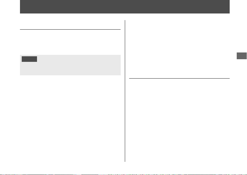
Warning Indicators On or Flashing
Low Oil Pressure Indicator
If the low oil pressure indicator comes on,
pull safely to the side of the road and stop
the engine.
NOTICE
Continuing to ride with low oil pressure can
cause serious damage to the engine.
1.
Check the engine oil level, and add oil as
necessary. 2 P. 143, 2 P. 144
2.
Start the engine.
u Only continue riding if the low oil
pressure indicator goes off.
Rapid acceleration may momentarily cause
the low oil pressure indicator to come on,
especially if the oil is at or near the low level.
If the low oil pressure indicator stays on when
the oil level is at the proper level, stop the
engine and contact your dealer.
If the engine oil level goes down rapidly, your
motorcycle may have a leak or another
serious problem. Have your motorcycle
inspected by your dealer.
PGM-FI (Programmed Fuel
Injection) Malfunction
Indicator Lamp (MIL)
If the indicator comes on while riding, you
may have a serious problem with the PGM-FI
system. Reduce speed and have your
motorcycle inspected by your dealer as soon
as possible.
20170830152249_31MKF6100_enu_BOOK Page 184 Wednesday, August 30 2017 15:45:50 JST
Troubleshooting
181

ABS (Anti-lock Brake System)
Indicator
CBR1000RA/S1/S2
If the indicator operates in one of the
following ways, you may have a serious
problem with the ABS. Reduce your speed
and have your motorcycle inspected by your
dealer as soon as possible.
● Indicator comes on or starts flashing while
riding.
● Indicator does not come on when the
ignition switch is in the ON position.
● Indicator does not go off at speeds above
6 mph (10 km/h).
If the ABS indicator stays on, your brakes will
continue to work as a conventional system,
but without the anti-locking function.
The ABS indicator may flash if you turn the
rear wheel while your motorcycle is lifted off
the ground. In this case, turn the ignition
switch to the OFF position, and then to the
ON position again. The ABS indicator will go
off after your speed reaches 19 mph (30
km/h).
HESD (Honda Electronic
Steering Damper) Indicator
If the indicator comes on while riding, you
may have a serious problem with the HESD.
Reduce speed and have your motorcycle
inspected by your dealer as soon as possible.
20170830152249_31MKF6100_enu_BOOK Page 185 Wednesday, August 30 2017 15:45:50 JST
Warning Indicators On or Flashing u ABS (Anti-lock Brake System) Indicator
Troubleshooting
182

Torque Control Indicator
If the indicator operates in one of the following
ways, you may have a serious problem with
the Torque Control. Reduce your speed and
have your motorcycle inspected by your
dealer as soon as possible.
●
Indicator comes and stays on (solid) while
riding.
●
Indicator does not come on when the
ignition switch is turned to the ON position.
●
Indicator does not go off at speeds above
3 mph (5 km/h).
Even when the Torque Control indicator is on,
your motorcycle will have normal riding ability
without Torque Control function.
u
When the indicator comes on while the
Torque Control is in operation, you will
have to completely close the throttle to
regain normal riding ability.
The Torque Control indicator may come on if
you rotate the rear wheel while your
motorcycle is lifted off the ground. In this case,
turn the ignition switch to the OFF position,
and then to the ON position again. The
Torque Control indicator will go off after your
speed reaches 3 mph (5 km/h).
CBR1000RR
The Torque Control indicator come on when
the front or rear wheel locks. In this case, the
Torque Control will not function.
In this case, turn the ignition switch to the OFF
position, and then to the ON position again.
The Torque Control indicator will go off after
your speed reaches 3 mph (5 km/h).
20170830152249_31MKF6100_enu_BOOK Page 186 Wednesday, August 30 2017 15:45:50 JST
Warning Indicators On or Flashing u Torque Control Indicator
Troubleshooting
183
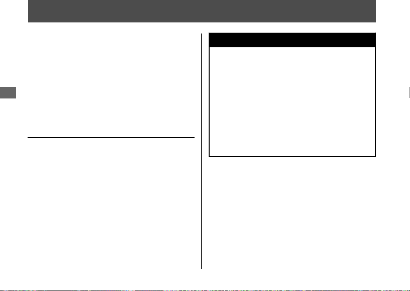
Tire Puncture
Repairing a puncture or removing a wheel
requires special tools and technical expertise.
We recommend you have this type of service
performed by your dealer.
After an emergency repair, always have the
tire inspected/replaced by your dealer.
Emergency Repair Using a Tire
Repair Kit
If your tire has a minor puncture, you can
make an emergency repair using a tubeless
tire repair kit.
Follow the instructions provided with the
emergency tire repair kit.
Riding your motorcycle with a temporary tire
repair is very risky. Do not exceed 30 mph
(50 km/h). Have the tire replaced by your
dealer as soon as possible.
3WARNING
Riding your motorcycle with a
temporary tire repair can be risky. If the
temporary repair fails, you can crash
and be seriously injured or killed.
If you must ride with a temporary tire
repair, ride slowly and carefully and do
not exceed 30 mph (50 km/h) until the
tire is replaced.
20170830152249_31MKF6100_enu_BOOK Page 187 Wednesday, August 30 2017 15:45:50 JST
Troubleshooting
184
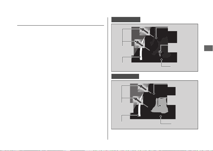
Removing Wheels
Follow these procedures if you need to
remove a wheel in order to repair a
puncture.
When removing and installing the wheel, be
careful not to damage the wheel speed
sensor and pulser ring.
#
Front Wheel
Removal
1.
Place your motorcycle on a firm, level
surface.
2.
Cover the both side of the front wheel
and brake caliper with protective tape or
cloth.
CBR1000RR/RA
CBR1000S1/S2
20170830152249_31MKF6100_enu_BOOK Page 188 Wednesday, August 30 2017 15:45:50 JST
Tire Puncture u Removing Wheels
Troubleshooting
185
Continued
Mounting
bolts
Tape or cloth
Brake caliper
Wheel speed
sensor
Pulser ring
Mounting
bolts
Tape or cloth
Brake caliper
Pulser ring
Wheel speed
sensor
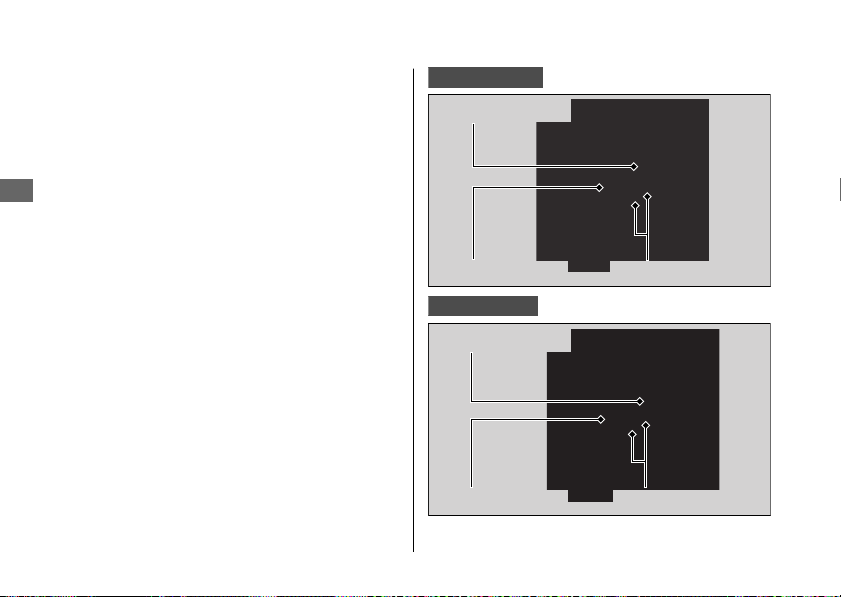
3.
On the right side, remove the mounting
bolts and remove the brake caliper.
4.
On the left side, remove the mounting
bolts and remove the brake caliper.
u Support the brake caliper assembly so
that it doesn't hang from the brake
hose. Do not twist the brake hose.
u Avoid getting grease, oil, or dirt on the
disc or pad surfaces.
u Do not pull the front brake lever while
the brake caliper is removed.
u Take care to prevent the brake caliper
from scratching the wheel during
removal.
5.
Remove the front axle bolt.
6.
Loosen the right axle pinch bolts.
7.
Support your motorcycle securely and
raise the front wheel off the ground using
a maintenance stand or a hoist.
CBR1000RR/RA
CBR1000S1/S2
20170830152249_31MKF6100_enu_BOOK Page 189 Wednesday, August 30 2017 15:45:50 JST
Tire Puncture u Removing Wheels
Troubleshooting
186
Axle pinch boltsFront axle bolt
Right side collar
Axle pinch boltsFront axle bolt
Right side collar
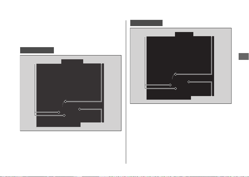
8.
Loosen the left axle pinch bolts.
9.
On the left side, withdraw the front axle
shaft, and remove the side collars and
wheel.
CBR1000RR/RA
CBR1000S1/S2
20170830152249_31MKF6100_enu_BOOK Page 190 Wednesday, August 30 2017 15:45:50 JST
Tire Puncture u Removing Wheels
Troubleshooting
187
Continued
Axle pinch bolts
Front axle shaft
Left side collar
Axle pinch bolts
Front axle shaft
Left side collar
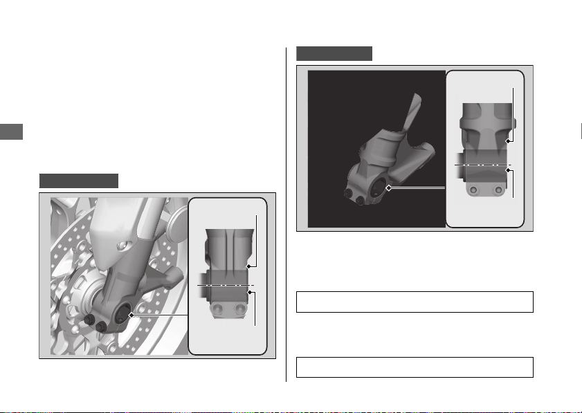
Installation
1.
Attach the side collars to the wheel.
2.
On the left side, place the wheel between
the fork legs and insert the lightly greased
front axle shaft to the end, through the
left fork leg and wheel hub.
3.
Align the end of the front axle shaft with
the surface of the fork leg.
CBR1000RR/RA
CBR1000S1/S2
4.
Tighten the left axle pinch bolts to hold
the axle.
5.
Tighten the axle bolt.
Torque: 58 lbf·ft (79 N·m, 8.1 kgf·m)
6.
Loosen the left axle pinch bolts.
7.
Tighten the right axle pinch bolts.
Torque: 16 lbf·ft (22 N·m, 2.2 kgf·m).
20170830152249_31MKF6100_enu_BOOK Page 191 Wednesday, August 30 2017 15:45:50 JST
Tire Puncture u Removing Wheels
Troubleshooting
188
Surface of
fork leg
End of front
axle shaft
Surface of
fork leg
End of front
axle shaft
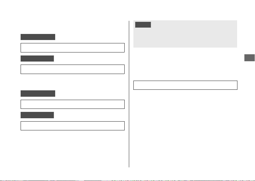
8.
Install the right brake caliper and tighten
the mounting bolts.
CBR1000RR/RA
Torque: 33 lbf·ft (45 N·m, 4.6 kgf·m).
CBR1000S1/S2
Torque: 30 lbf·ft (40 N·m, 4.1 kgf·m).
9.
Install the left brake caliper and tighten
the mounting bolts.
CBR1000RR/RA
Torque: 33 lbf·ft (45 N·m, 4.6 kgf·m).
CBR1000S1/S2
Torque: 30 lbf·ft (40 N·m, 4.1 kgf·m).
u Take care to prevent the brake caliper
from scratching the wheel during
installation.
u Use new mounting bolts when
installing the brake caliper.
NOTICE
When installing a wheel or caliper into original
position, carefully fit the brake disc between the
pads to avoid scratching them.
10.
Lower the front wheel on the ground.
11.
Apply the brake lever several times. Then,
pump the fork several times.
12.
Retighten the left axle pinch bolts.
Torque: 16 lbf·ft (22 N·m, 2.2 kgf·m).
13.
Raise the front wheel off the ground
again, and check that the wheel rotates
freely after you release the brake.
14.
Uncover the protective tape or cloth.
If a torque wrench was not used for
installation, see your dealer as soon as
possible to verify proper assembly.
Improper assembly may lead to loss of
braking capacity.
20170830152249_31MKF6100_enu_BOOK Page 192 Wednesday, August 30 2017 15:45:50 JST
Tire Puncture u Removing Wheels
Troubleshooting
189
Continued
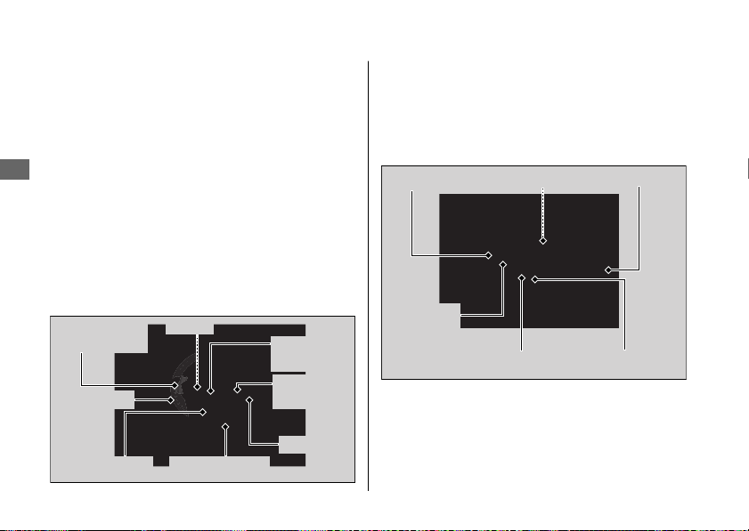
#
Rear Wheel
Removal
1.
Place your motorcycle on a firm, level
surface.
2.
Support your motorcycle securely and
raise the rear wheel off the ground using a
maintenance stand or a hoist.
3.
Loosen the rear axle nut, lock nuts and
turn the adjusting bolts so the rear wheel
can be moved all the way forward for
maximum drive chain slack.
4.
Remove the rear axle nut and washer.
5.
Remove the drive chain from the driven
sprocket by pushing the rear wheel
forward.
6.
Remove the rear axle shaft, adjusting
plates.
20170830152249_31MKF6100_enu_BOOK Page 193 Wednesday, August 30 2017 15:45:50 JST
Tire Puncture u Removing Wheels
Troubleshooting
190
Lock nut
Collar
Washer Rear axle nut
Adjusting
bolt
Adjusting
plate
Wheel speed
sensor
Pulser ring
Rear axle shaft
Lock nut
Drive chain
Adjusting
bolt
Collar
Adjusting plate

7.
Remove the brake caliper bracket, rear
wheel and side collars.
u Support the brake caliper assembly so
that it doesn’t hang from the brake
hose. Do not twist the brake hose.
u Avoid getting grease, oil, or dirt on the
disc or pad surfaces.
u Do not push the brake pedal while the
wheel is removed.
Installation
1.
To install the rear wheel, reverse the
removal procedure.
u Take care to prevent the brake caliper
from scratching the wheel during
installation.
NOTICE
When installing a wheel or caliper into original
position, carefully fit the brake disc between the
pads to avoid scratching them.
20170830152249_31MKF6100_enu_BOOK Page 194 Wednesday, August 30 2017 15:45:50 JST
Tire Puncture u Removing Wheels
Troubleshooting
191
Continued
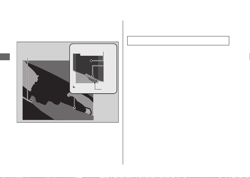
2.
Make sure that the lug on the brake
caliper bracket is positioned in the slot on
the swingarm.
3.
Adjust the drive chain. 2 P. 154
4.
Install and tighten the rear axle nut.
Torque: 100 lbf·ft (135 N·m, 13.8 kgf·m).
5.
After installing the wheel, apply the brake
pedal several times, then check if the
wheel rotates freely. Recheck the wheel if
the brake drags or if the wheel does not
rotate freely.
If a torque wrench was not used for
installation, see your dealer as soon as
possible to verify proper assembly.
Improper assembly may lead to loss of
braking capacity.
20170830152249_31MKF6100_enu_BOOK Page 195 Wednesday, August 30 2017 15:45:50 JST
Tire Puncture u Removing Wheels
Troubleshooting
192
Brake caliper
bracket
Swingarm
Lug
Slot
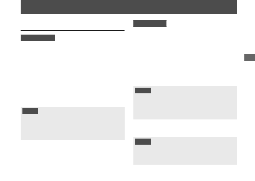
Electrical Trouble
Battery Goes Dead
CBR1000RR/RA
Charge the battery using a motorcycle
battery charger.
Remove the battery from the motorcycle
before charging.
Do not use an automobile-type battery
charger, as these can overheat a motorcycle
battery and cause permanent damage. If the
battery does not recover after recharging,
contact your dealer.
NOTICE
Jump starting using an automobile battery can
damage your motorcycle's electrical system and
is not recommended.
Bump starting is also not recommended.
CBR1000S1/S2
Battery charging is needed.
A battery charger recommended by your
lithium-ion (li-ion) battery manufacturer is
needed for battery charging.
Contact your dealer before charging the
battery.
Remove the battery from the motorcycle
before charging.
NOTICE
Only use a charger recommended by your
lithium-ion (li-ion) battery manufacturer. Using a
battery charger that is not recommended can
cause permanent damage to your battery.
If the battery does not recover after
recharging, contact your dealer.
NOTICE
Do not jump-start, as this can damage your
motorcycle's electrical system and battery.
Bump starting is not recommended.
20170830152249_31MKF6100_enu_BOOK Page 196 Wednesday, August 30 2017 15:45:50 JST
Troubleshooting
193

Burned-out Light Bulb
All light bulbs on the motorcycle are LEDs. If
there is a LED which is not turned on, see
your dealer for servicing.
#
Headlight
The headlights use several LEDs.
If there is a LED which is not turned on, see
your dealer for servicing.
20170830152249_31MKF6100_enu_BOOK Page 197 Wednesday, August 30 2017 15:45:50 JST
Electrical Trouble u Burned-out Light Bulb
Troubleshooting
194
Headlights
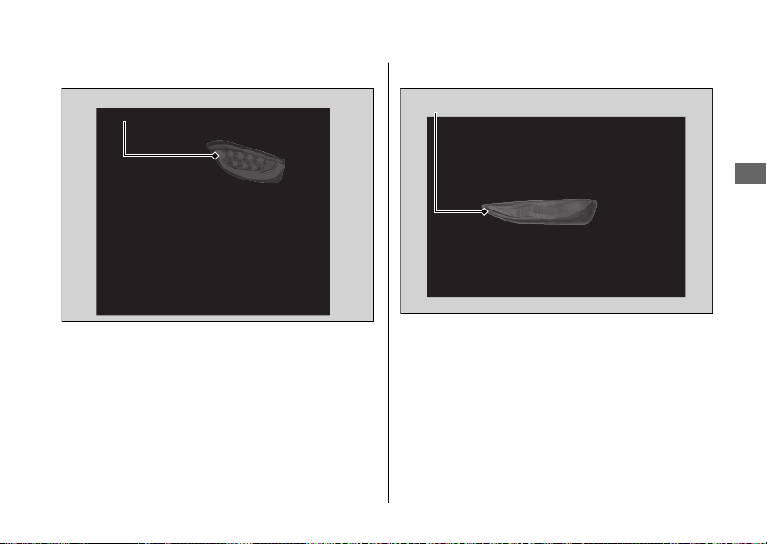
#
Brake light/Taillight
The brake light and taillight uses several
LEDs.
If there is a LED which is not turned on, see
your dealer for servicing.
#
Front Turn Signal Light
The front turn signal light uses several LEDs.
If there is a LED which is not turned on, see
your dealer for servicing.
20170830152249_31MKF6100_enu_BOOK Page 198 Wednesday, August 30 2017 15:45:50 JST
Electrical Trouble u Burned-out Light Bulb
Troubleshooting
195
Continued
Brake light/Taillight
Front turn signal light
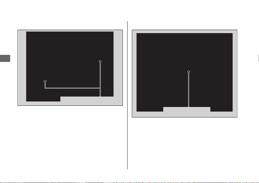
#
Rear Turn Signal Light
The rear turn signal light uses several LEDs.
If there is a LED which is not turned on, see
your dealer for servicing.
#
License Plate Light
The license plate light uses a LED.
If there is a LED which is not turned on, see
your dealer for servicing.
20170830152249_31MKF6100_enu_BOOK Page 199 Wednesday, August 30 2017 15:45:50 JST
Electrical Trouble u Burned-out Light Bulb
Troubleshooting
196
Rear turn signal lights
License plate light
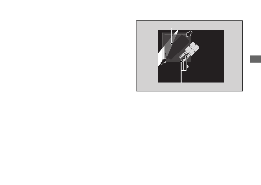
Blown Fuse
Before handling fuses, see “Inspecting and
Replacing Fuses.” 2 P. 129
#
Fuse Box Fuses
1.
Remove the front seat. 2 P. 139
2.
Remove the fuse box cover.
3.
Pull the fuses out one by one with the
fuse puller in the tool kit and check for a
blown fuse. Always replace a blown fuse
with a spare fuse of the same rating.
4.
Reinstall the fuse box cover.
5.
Reinstall the front seat.
20170830152249_31MKF6100_enu_BOOK Page 200 Wednesday, August 30 2017 15:45:50 JST
Electrical Trouble u Blown Fuse
Troubleshooting
197
Continued
Fuse box cover
Spare fuses
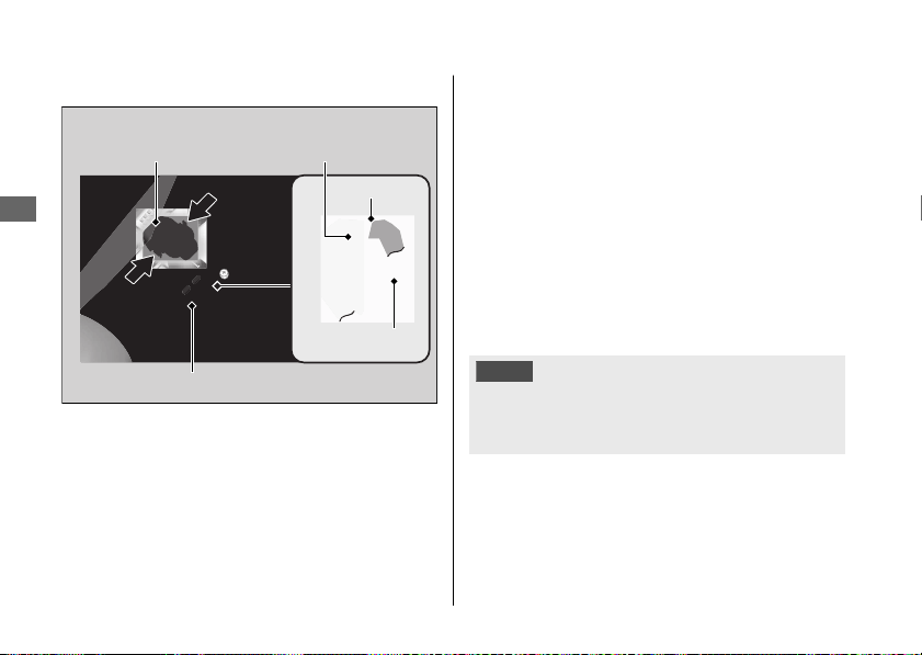
#
Main Fuse & FI Fuse
1.
Remove the front seat. 2 P. 139
2.
Remove the starter magnetic switch
cover.
3.
Pull the main fuse and FI fuse out one by
one and check for a blown fuse. Always
replace a blown fuse with a spare of the
same rating.
u Spare main fuses are provided in the
fuse box. 2 P. 197
4.
Reinstall parts in the reverse order of
removal.
NOTICE
If a fuse fails repeatedly, you likely have an
electrical problem. Have your motorcycle
inspected by your dealer.
20170830152249_31MKF6100_enu_BOOK Page 201 Wednesday, August 30 2017 15:45:50 JST
Electrical Trouble u Blown Fuse
Troubleshooting
198
Starter magnetic switch
Main fuse
FI fuse
Starter magnetic
switch cover
Spare FI fuse

Keys..................................................................... P. 200
Instruments, Controls, & Other Features...P. 201
Caring for Your Motorcycle
..........................P. 203
Storing Your Motorcycle ............................... P. 207
Transporting Your Motorcycle.....................P. 208
You & the Environment .................................P. 209
Vehicle Identification Number.....................P. 210
Emission Control Systems............................. P. 211
Catalytic Converter ......................................... P. 215
Oxygenated Fuels............................................P. 216
Authorized Manuals ....................................... P. 217
Warranty Coverage and Service .................. P. 218
Honda Contacts............................................... P. 220
USA
Reporting Safety Defects..................... P. 222
20170830152249_31MKF6100_enu_BOOK Page 202 Wednesday, August 30 2017 15:45:50 JST
Information
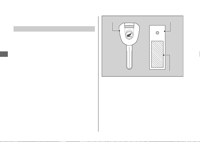
Keys
Ignition Key
This motorcycle has two ignition keys and a key
tag with a key number and a bar code. Store
the spare key and the key tag in a safe location.
To make a duplicate key, take the spare key and
the key tag to your dealer or a locksmith.
If you lose all keys and the key tag, the ignition
switch assembly will probably have to be
removed by your dealer to determine the key
number.
A metal key holder may cause damage to the
area surrounding the ignition switch.
20170830152249_31MKF6100_enu_BOOK Page 203 Wednesday, August 30 2017 15:45:50 JST
Keys
Information
200
Ignition key Key tag
Key number and bar code

Instruments, Controls, &
Other Features
Ignition Switch
Leaving the ignition switch in the ON position
with the engine stopped will drain the battery.
Do not turn the key while riding.
Engine Stop Switch
Do not use the engine stop switch except in an
emergency. Doing so when riding will cause the
engine to suddenly turn off, making riding
unsafe.
If you stop the engine using the engine stop
switch, turn the ignition switch to the OFF
position. Failing to do so will drain the battery.
Odometer
The display locks at 999,999 when the read-out
exceeds 999,999.
Tripmeter
The tripmeters return to 0.0 when each read-
out exceeds 9,999.9.
Document Bag
CBR1000RR/RA
The owner’s manual, registration, and insurance
information can be stored in the plastic
document bag on the underside of the rear
seat. 2 P. 113, 2 P. 140
CBR1000S1/S2
The owner’s manual, registration, and insurance
information can be stored in the plastic
document bag on the underside of the single
seat cowl. 2 P. 113, 2 P. 141
20170830152249_31MKF6100_enu_BOOK Page 204 Wednesday, August 30 2017 15:45:50 JST
Instruments, Controls, & Other Features
Information
201
Continued

Ignition Cut-off System
A banking (lean angle) sensor automatically
stops the engine and fuel pump if the
motorcycle falls over. To reset the sensor, you
must turn the ignition switch to the OFF position
and back to the ON position before the engine
can be restarted.
HESD
The Honda Electronic Steering Damper (HESD)
automatically controls the steering damper
characteristics in accordance with vehicle speed
and acceleration.
HESD Indicator Comes On 2 P. 182
Assist-slipper Clutch System
The assist-slipper clutch system helps to prevent
the rear tire from locking up when the
deceleration of your motorcycle produces a
strong engine braking effect. It also makes the
clutch lever operation feel lighter.
Use only MA classification engine oil for your
motorcycle. Using engine oil other than MA
classification oil could result in damage to the
assist-slipper clutch system.
Throttle by Wire System
This model is equipped with a Throttle by Wire
System.
Do not put magnetized items or items
susceptible to magnetic interference near the
right handlebar switches.
20170830152249_31MKF6100_enu_BOOK Page 205 Wednesday, August 30 2017 15:45:50 JST
Instruments, Controls, & Other Features
Information
202
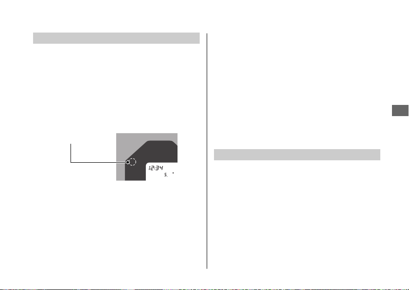
Automatic Brightness Control
The backlight brightness of the meter will be
controlled automatically when “AUTO” is
selected on the brightness setting.
Ambient brightness is detected by the
photosensor.
Do not damage or cover the photosensor.
Otherwise, the automatic brightness control
may not work properly.
Caring for Your Motorcycle
Frequent cleaning and polishing is important to
ensure the life of your Honda. A clean
motorcycle makes it easier to spot potential
problems.
In particular, seawater and salts used to prevent
ice on roads promote the formation of
corrosion. Always wash your motorcycle
thoroughly after riding on coastal or treated
roads.
Washing
Allow the engine, muffler, brakes, and other
high-temperature parts to cool before washing.
1.
Rinse your motorcycle thoroughly using a
low pressure garden hose to remove loose
dirt.
2.
If necessary, use a sponge or a soft towel
with mild cleaner to remove road grime.
u Clean the windscreen, headlight lens,
panels, and other plastic components
with extra care to avoid scratching them.
20170830152249_31MKF6100_enu_BOOK Page 206 Wednesday, August 30 2017 15:45:50 JST
Caring for Your Motorcycle
Information
203
Continued
Photosensor

Avoid directing water into the air cleaner,
muffler, and electrical parts.
3.
Thoroughly rinse your motorcycle with
plenty of clean water and dry with a soft,
clean cloth.
4.
After the motorcycle dries, lubricate any
moving parts.
u Make sure that no lubricant spills onto
the brakes or tires. Brake discs, pads,
drum or shoes contaminated with oil will
suffer greatly reduced braking
effectiveness and can lead to a crash.
5.
Lubricate the drive chain immediately after
washing and drying the motorcycle.
6.
Apply a coat of wax to prevent corrosion.
u Avoid products that contain harsh
detergents or chemical solvents. These
can damage the metal, paint, and plastic
on your motorcycle.
Keep the wax clear of the tires and
brakes.
u If your motorcycle has any matte painted
parts, do not apply a coat of wax to the
matte painted surface.
#
Washing Precautions
Follow these guidelines when washing:
● Do not use high-pressure washers:
u High-pressure water cleaners can
damage moving parts and electrical
parts, rendering them inoperable.
u Water in the air intake can be drawn into
the throttle body and/or enter the air
cleaner.
● Do not direct water at the muffler:
u Water in the muffler can prevent starting
and causes rust in the muffler.
● Dry the brakes:
u Water adversely affects braking
effectiveness. After washing, apply the
brakes intermittently at low speed to
help dry them.
● Do not direct water under the seat:
u Water in the under seat compartment
can damage your documents and other
belongings.
20170830152249_31MKF6100_enu_BOOK Page 207 Wednesday, August 30 2017 15:45:50 JST
Caring for Your Motorcycle
Information
204

●
CBR1000S1/S2
Do not direct water under the single seat
cowl:
u Water in the under single seat cowl
compartment can damage your
documents and other belongings.
● Do not direct water at the air cleaner:
u Water in the air cleaner can prevent the
engine from starting.
● Do not direct water near the headlight:
u The headlight's inside lens may fog
temporarily after washing or while riding
in the rain. This does not impact the
headlight function.
However, if you see a large amount of
water or ice accumulated inside the
lens(es), have your vehicle inspected by
your dealer.
● Do not use wax or polishing compounds on
matte painted surface:
u Use a soft cloth or sponge, plenty of
water, and a mild detergent to clean
matte painted surfaces. Dry with a soft
clean cloth.
20170830152249_31MKF6100_enu_BOOK Page 208 Wednesday, August 30 2017 15:45:50 JST
Caring for Your Motorcycle
Information
205
Continued
Aluminum Components
Aluminum will corrode from contact with dirt,
mud, or road salt. Clean aluminum parts
regularly and follow these guidelines to avoid
scratches:
● Do not use stiff brushes, steel wool, or
cleaners containing abrasives.
● Avoid riding over or scraping against curbs.
Panels
Follow these guidelines to prevent scratches
and blemishes:
● Wash gently using a soft sponge and plenty
of water.
● To remove stubborn stains, use diluted
detergent and rinse thoroughly with plenty
of water.
● Avoid getting gasoline, brake fluid, or
detergents on the instruments, panels, or
headlight.
Windscreen
Using plenty of water, clean the windscreen with
a soft cloth or sponge. (Avoid using detergents
or any kind of chemical cleaner on the
windscreen.) Dry with a soft, clean cloth.
NOTICE
To avoid possible scratching or other damage, use
only water and a soft cloth or sponge to clean the
windscreen.
For a dirtier windscreen, use a diluted neutral
detergent with a sponge and plenty of water.
Make sure to wash off all the detergent.
(Detergent residue may cause windscreen
cracks.)
Replace the windscreen if scratches cannot be
removed and they obstruct clear vision.
Take care to keep battery electrolyte, brake
fluid, or other chemical solvents off the
windscreen and screen garnish. They will
damage the plastic.
20170830152249_31MKF6100_enu_BOOK Page 209 Wednesday, August 30 2017 15:45:50 JST
Caring for Your Motorcycle
Information
206

Exhaust Pipe and Muffler
The exhaust pipe and muffler are titanium and
stainless steel but may become stained by mud
or dust.
To remove mud or dust, use a wet sponge and
a liquid kitchen abrasive, then rinse well with
clean water. Dry with chamois or a soft towel.
If necessary, remove heat stains by using a
commercially available fine texture compound.
Then rinse by the same manner as removing
mud or dust.
NOTICE
Even though the exhaust is made of titanium and
stainless steel, it can become stained. Remove all
marks and blemishes as soon as they are noticed.
Storing Your Motorcycle
If you store your motorcycle outdoors, you
should consider using a full-body motorcycle
cover.
If you won't be riding for an extended period,
follow these guidelines:
● Wash your motorcycle and wax all painted
surfaces (except matte painted surfaces).
Coat chrome pieces with rust-inhibiting oil.
● Lubricate the drive chain. 2 P. 131
● Place your motorcycle on a maintenance
stand and position a block so that both tires
are off the ground.
● After rain, remove the body cover and allow
the motorcycle to dry.
20170830152249_31MKF6100_enu_BOOK Page 210 Wednesday, August 30 2017 15:45:50 JST
Storing Your Motorcycle
Information
207
Continued
● Remove the battery (2 P. 137) to prevent
discharge. Fully charge the battery and then
place it in a shaded, well-ventilated area.
u If you leave the battery in place,
disconnect the negative
- terminal to
prevent discharge.
After removing your motorcycle from storage,
inspect all maintenance items required by the
Maintenance Schedule.
USA
For more information about storage, refer
to the Honda Winter Storage Guide, available
from your dealer.
Canada
For more information about storage,
visit our website at www.honda.ca and look up
“Storage Tips” under the “Honda Warranty” in
the Warranty tab for your Model.
Transporting Your
Motorcycle
If your motorcycle needs to be transported, it
should be carried on a motorcycle trailer or a
flatbed truck or trailer that has a loading ramp
or lifting platform, and motorcycle tie-down
straps. Never try to tow your motorcycle with a
wheel or wheels on the ground.
NOTICE
Towing your motorcycle can cause serious
damage to the transmission.
20170830152249_31MKF6100_enu_BOOK Page 211 Wednesday, August 30 2017 15:45:50 JST
Transporting Your Motorcycle
Information
208

You & the Environment
Owning and riding a motorcycle can be
enjoyable, but you must do your part to protect
the environment.
Choose Sensible Cleaners
Use a biodegradable detergent when you wash
your motorcycle. Avoid aerosol spray cleaners
that contain chlorofluorocarbons (CFCs) which
damage the atmosphere's protective ozone
layer.
Recycle Wastes
Put oil and other toxic wastes in approved
containers and take them to a recycling center.
Call your local or state office of public works or
environmental services to find a recycling center
in your area, and to get instructions on how to
dispose of non-recyclable wastes. Do not place
used engine oil in the trash, or pour it down a
drain or on the ground. Used oil, gasoline,
coolant, and cleaning solvents contain poisons
that can hurt refuse workers and contaminate
drinking water, lakes, rivers, and oceans.
20170830152249_31MKF6100_enu_BOOK Page 212 Wednesday, August 30 2017 15:45:50 JST
You & the Environment
Information
209
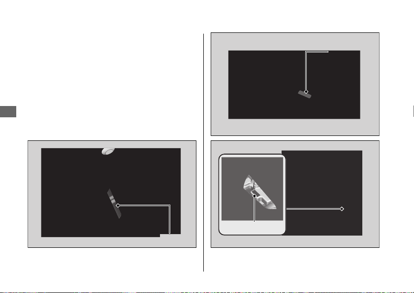
Vehicle Identification
Number
The VIN and engine serial number uniquely
identify your motorcycle and are required in
order to register your motorcycle. They may
also be required when ordering replacement
parts.
You should record these numbers and keep
them in a safe place.
20170830152249_31MKF6100_enu_BOOK Page 213 Wednesday, August 30 2017 15:45:50 JST
Vehicle Identification Number
Information
210
VIN
VIN
Engine number
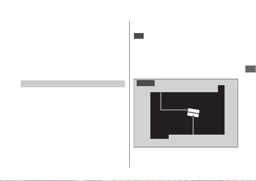
Emission Control Systems
Your motorcycle engine emits combustion
byproducts, including carbon monoxide (CO),
oxides of nitrogen (NOx), and hydrocarbons
(HC). Gasoline evaporation also emits
hydrocarbons. Controlling the production of
NOx, CO, and HC is important for the
environment.
Exhaust Emission Requirements
The U.S. Environmental Protection Agency
(EPA), the California Air Resources Board
(CARB), and Environment and Climate Change
Canada (ECCC) require that your motorcycle
comply with applicable exhaust, crankcase, and
fuel permeation emission standards during its
useful life, when operated and maintained
according to the instructions provided.
CARB also requires that your motorcycle
comply with applicable evaporative emission
requirements during its useful life, when
operated and maintained according to the
instructions provided.
USA
Compliance with the terms of the
Distributor's Warranties for Honda Motorcycle
Emission Control Systems is necessary in order
to maintain a valid emissions system warranty.
The Vehicle Emission Control Information label
is located on the left side of the swingarm.
20170830152249_31MKF6100_enu_BOOK Page 214 Wednesday, August 30 2017 15:45:50 JST
Emission Control Systems
Information
211
Continued
Canada
Vehicle emission control
information label
Vehicle emission control
information label

Noise Emission Requirements
The EPA requires that motorcycles built after
January 1, 1983 comply with applicable noise
emission standards for one year or 3,730 miles
(6,000 km) after the time of purchase when
operated and maintained according to the
instructions provided.
Exhaust Emission Control System
The exhaust emission control system includes
the following components that should not need
adjustment, although periodic inspection by
your dealer is recommended.
#
PGM-FI System
The PGM-FI (programmed fuel injection) system
uses sequential multiport fuel injection, and is
comprised of air intake, engine control, fuel
control, and exhaust control subsystems. The
engine control module (ECM) uses sensors to
determine how much air enters the engine, and
then controls how much fuel to inject.
#
Ignition Timing Control System
The ignition timing control system adjusts the
ignition timing to reduce the amount of HC,
CO, and NOx produced.
#
Secondary Air Injection System
The secondary air injection system adds filtered
air into the exhaust gas to help improve
emission control performance.
#
Catalytic Converters
The exhaust system contains one or more
catalytic converters. Catalytic converters use a
catalyst to convert most of the harmful exhaust
gas compounds into harmless compounds.
Evaporative Emission Control System
50 STATE (meets California)
An evaporative emissions control system uses a
canister filled with charcoal to adsorb fuel vapor
from the fuel tank while the engine is off. The
vapor is drawn into the engine and burned
while riding.
20170830152249_31MKF6100_enu_BOOK Page 215 Wednesday, August 30 2017 15:45:50 JST
Emission Control Systems
Information
212

Crankcase Emissions Control System
The engine is equipped with a closed crankcase
system to prevent discharging crankcase
emissions into the atmosphere.
Blow-by gas is returned to the combustion
chamber through the air cleaner housing and
throttle body.
Fuel Permeation Emission Control
The fuel tank, fuel hoses, and fuel vapor charge
hoses use fuel permeation control technologies
to prevent fuel vapor emissions. Tampering with
these components to reduce or defeat the
effectiveness of the fuel permeation
technologies is prohibited.
Noise Emission Control System
#
TAMPERING WITH THE NOISE CONTROL
SYSTEM IS PROHIBITED:
U. S. federal law prohibits, and Canadian
provincial laws may prohibit, the following acts
or the causing thereof: (1) The removal or
rendering inoperative by any person, other than
for purposes of maintenance, repair or
replacement, of any device or element of
design incorporated into any new vehicle for
the purpose of noise control prior to its sale or
delivery to the ultimate purchaser or while it is
in use; or (2) the use of the vehicle after such
device or element of design has been removed
or rendered inoperative by any person.
20170830152249_31MKF6100_enu_BOOK Page 216 Wednesday, August 30 2017 15:45:50 JST
Emission Control Systems
Information
213
Continued

#
AMONG THOSE ACTS PRESUMED TO
CONSTITUTE TAMPERING ARE THE
FOLLOWING ACTS:
● Removal of, or puncturing the muffler,
baffles, header pipes or any other
component which conducts exhaust gases.
● Removal of, or puncturing of any part of the
intake system.
● Lack of proper maintenance.
● Removing or disabling any emissions
compliance component, or replacing any
compliance component with a noncompliant
component.
Problems Affecting Motorcycle Exhaust
Emissions
Have your motorcycle inspected and repaired
by your dealer if you experience any of the
following symptoms:
● Hard starting or stalling after starting
● Rough idling
● Misfiring or backfiring during acceleration
● Poor engine performance and poor fuel
economy
20170830152249_31MKF6100_enu_BOOK Page 217 Wednesday, August 30 2017 15:45:50 JST
Emission Control Systems
Information
214

Catalytic Converter
This motorcycle is equipped with a three-way
catalytic converter. The catalytic converter
contains precious metals that serve as catalysts
in high temperature chemical reactions that
convert hydrocarbons (HC), carbon monoxide
(CO), and oxides of nitrogen (NOx) in the
exhaust gasses into safe compounds.
A defective catalytic converter contributes to air
pollution and can impair your engine's
performance. A replacement unit must be an
original Honda part or equivalent.
Follow these guidelines to protect your
motorcycle's catalytic converter.
● Always use unleaded gasoline. Leaded
gasoline will damage the catalytic converter.
● Keep the engine in good running condition.
A poorly running engine can cause the
catalytic converter to overheat causing
damage to the converter or the motorcycle.
● If your engine is misfiring, backfiring, stalling,
or otherwise not running properly, stop
riding and turn off the engine. Have your
motorcycle serviced as soon as possible.
20170830152249_31MKF6100_enu_BOOK Page 218 Wednesday, August 30 2017 15:45:50 JST
Catalytic Converter
Information
215

Oxygenated Fuels
Some conventional fuels blended with alcohol
or an ether compound are available in some
locales to help reduce emissions to meet clean
air standards. These gasolines are collectively
referred to as oxygenated fuels. If you plan to
use oxygenated fuel, check that it is unleaded
and meets the minimum octane rating and
blend requirement.
The following fuel blends are EPA-approved
and have been approved for use in your
motorcycle:
● Ethanol (ethyl alcohol) up to 10% by volume.
u Gasoline containing ethanol may be
marketed under the name Gasohol.
● Methanol (methyl alcohol) up to 5% by
volume that contain cosolvents and
corrosion inhibitors to protect the fuel
system. Never use a blend containing more
than 5%.
If you accidentally fill your fuel tank with an
oxygenated fuel containing higher percentages,
you may experience performance problems. To
resolve the problem, have your dealer drain the
fuel tank and replace with the correct fuel. Fuel
system or performance problems resulting from
the use of an oxygenated fuel containing higher
percentages are not covered by your warranty.
NOTICE
Improper use of oxygenated fuels can damage
metal, rubber, and plastic parts of your fuel
system.
Oxygenated fuel can also damage paint.
Damage caused by spilled fuel is not covered by
warranty.
If you notice any undesirable operating
symptoms or performance problems, try a
different brand of gasoline.
20170830152249_31MKF6100_enu_BOOK Page 219 Wednesday, August 30 2017 15:45:50 JST
Oxygenated Fuels
Information
216
Publication Item No. Description
61MKF01 2018 CBR1000RR/RA/S1/S2 Service Manual
61CSM00 Common Service Manual
S9507
USA
Winter Storage Guide
31MKF610 2018 CBR1000RR/RA/S1/S2 Owner’s Manual
Authorized Manuals
USA
The Service Manual used by your
authorized dealer is available from your Honda
dealer or Helm, Inc.
Canada
See your dealer to order authorized
manuals.
Also available, but not necessary to service your
model, is the Honda Common Service Manual,
which explains basic service information for
various systems on Honda motorcycles,
scooters, and ATV.
USA
The Winter Storage Guide in conjunction
with the Owner's Manual and Service Manual
can help you prepare your Honda motorcycle,
scooter, ATV, and SxS for winter storage.
These Honda manuals are written for the
professional technician. However, if you possess
the proper tools, observe the safety standards,
and are mechanically capable, you should find
them easy to use.
Special Honda tools are necessary for some
procedures.
USA
Order On-Line: www.helminc.com
Order Toll Free: 1-888-CYCLE93
(1-888-292-5393)
(NOTE: For Credit Card Orders Only)
Monday - Friday 8:00 AM - 6:00 PM EST
20170830152249_31MKF6100_enu_BOOK Page 220 Wednesday, August 30 2017 15:45:50 JST
Authorized Manuals
Information
217
Warranty Coverage and
Service
Coverage
Your new Honda is covered by the following
warranties:
● Motorcycle Limited Warranty
● Emission Control System Warranty
●
USA
Noise Control Warranty
The responsibilities, restrictions, and exclusions
that apply to these warranties are explained in
the Warranties Booklet given to you by your
Honda dealer at the time of purchase. Always
keep your Honda owner's card with your
Warranties Booklet.
Canada
Please refer to the Warranty Booklet
posted on our website at www.honda.ca.
It is important to realize that your warranty
applies only to defects in material or
workmanship of your Honda. Your warranty
coverage does not apply to the normal wear
and deterioration associated with use of the
motorcycle.
Your warranty coverage is not voided if you
perform your own maintenance. However,
failures that occur due directly to improper
maintenance are not covered by these
warranties.
USA
You can extend almost all of your warranty
coverage through the Honda Protection Plan.
For more information, see your Honda dealer.
20170830152249_31MKF6100_enu_BOOK Page 221 Wednesday, August 30 2017 15:45:50 JST
Warranty Coverage and Service
Information
218

Service
Please remember that maintenance
recommended in the Maintenance Schedule is
not included in your warranty coverage.
If you believe you have a problem with your
motorcycle, call the service department of your
Honda dealer. Make an appointment for an
inspection and diagnosis. You will be asked to
authorize that inspection, and your dealer will
return the results of the inspection. If a problem
exists and is covered under warranty, your
dealer will perform the warranty repairs. If you
have any questions about your warranty
coverage or the nature of the repair, talk to the
Service Manager of your Honda dealer.
If a misunderstanding occurs and you aren't
satisfied with your dealer's handling of the
situation, we suggest you discuss your problem
with the appropriate member of the
dealership's management team. If you are still
not satisfied, contact the owner of the
dealership or their designated representative.
20170830152249_31MKF6100_enu_BOOK Page 222 Wednesday, August 30 2017 15:45:50 JST
Warranty Coverage and Service
Information
219

Honda Contacts
American Honda Motor Co., Inc.
If you wish to contact Honda directly to
comment on your experiences with your
motorcycle or with your dealer, please send
your comments to the following address:
Motorcycle Division,
American Honda Motor Co., Inc.,
P.O. Box 2200, Torrance,
CA 90509-2200
Mailstop: 100-4C-7B,
Telephone: (866) 784-1870.
Canada
Honda Canada Inc.
Customer Relations Department,
180 Honda Boulevard
Markham, Ontario
L6C 0H9
Telephone: (888) 946-6329
Fax: (877) 939-0909
E-mail: [email protected]
Please include the following information in your
letter:
● Name, address, and telephone number
● Product model, year, and VIN
● Date of purchase
● Dealer name and address
We will likely ask your Honda dealer to respond,
or possibly acknowledge your comments
directly.
20170830152249_31MKF6100_enu_BOOK Page 223 Wednesday, August 30 2017 15:45:50 JST
Honda Contacts
Information
220

Your Honda Dealer
The service department of your Honda dealer
offers trained personnel to perform regular
maintenance and most repairs. It has the latest
available service information from Honda and
also handles warranty inspections and repairs.
The parts department offers Honda Genuine
Parts, Pro Honda products, Honda Genuine
Accessories (USA only), and Honda accessories
and products (Canada only) that provide the
same quality that went into your motorcycle.
USA
The sales department offers the Honda
Protection Plan to extend almost all of your
warranty coverage.
Your Honda dealer can also supply information
about, riding events, and information about
safety training available in your local area, and
the Honda Rider's Club of America (USA only).
Honda Rider's Club of America (HRCA)
The Honda Rider's Club of America (HRCA)
sponsors local riding chapters at Authorized
Honda Dealerships across the country.
20170830152249_31MKF6100_enu_BOOK Page 224 Wednesday, August 30 2017 15:45:50 JST
Honda Contacts
Information
221

USA
Reporting Safety
Defects
If you believe that your vehicle has a
defect which could cause a crash or
could cause injury or death, you should
immediately inform the National
Highway Traffic Safety Administration
(NHTSA) in addition to notifying
American Honda Motor Co., Inc.
If NHTSA receives similar complaints, it
may open an investigation, and if it
finds that a safety defect exists in a
group of vehicles, it may order a recall
and remedy campaign. However,
NHTSA cannot become involved in
individual problems between you, your
dealer, or American Honda Motor Co.,
Inc.
To contact NHTSA, you may call the
Vehicle Safety Hotline toll-free at:
1-888-327-4236
(TTY: 1-800-424-9153); go to
http://www.safercar.gov;
or write to:
Administrator, NHTSA,
1200 New Jersey Avenue, SE.,
Washington, DC 20590.
You can also obtain other information
about motor vehicle safety from:
http://www.safercar.gov.
20170830152249_31MKF6100_enu_BOOK Page 225 Wednesday, August 30 2017 15:45:50 JST
Reporting Safety Defects
Information
222
Specifications
■ Main Components
Overall length 81.3 in (2,065 mm)
Overall width 28.3 in (720 mm)
Overall height 44.3 in (1,125 mm)
Wheelbase 55.3 in (1,405 mm)
Minimum ground
clearance
5.1 in (130 mm)
Caster angle 23.3°
Trail 3.8 in (96 mm)
Curb weight
CBR1000RR
430 lb (195 kg)
CBR1000RA
USA model
434 lb (197 kg)
CBR1000RA
Canada model
432 lb (196 kg)
CBR1000S1
USA model
432 lb (196 kg)
CBR1000S1
Canada model
430 lb (195 kg)
CBR1000S2
430 lb (195 kg)
Maximum weight
capacity
CBR1000RR/RA
*1
366 lb (166 kg)
CBR1000S1/S2
*2
243 lb (110 kg)
Passenger capacity
CBR1000RR/RA
Rider and 1
passenger
CBR1000S1/S2
Rider only (no
passenger)
Minimum turning radius
10.5 ft (3.20 m)
Displacement 61.0 cu-in (1,000 cm
3
)
Bore x stroke
2.99 x 2.17 in (76.0 x 55.1 mm)
Compression ratio 13.0:1
Fuel
Unleaded gasoline
Recommended: 91 PON or higher
Tank capacity 4.28 US gal (16.2 L)
Battery
CBR1000RR/RA
YTZ7S
12 V-6 Ah (10 HR)
CBR1000S1/S2
HY93 lithium-ion (li-ion)
12 V-4.5 Ah (20 HR)
Gear ratio
1st 2.285
2nd 1.777
3rd 1.500
4th 1.333
5th 1.214
6th 1.137
Reduction ratio
(primary / final)
1.717 / 2.688
*1 : Including rider, passenger, all luggages, and accessories
*2 : Including rider, all luggages, and accessories
20170830152249_31MKF6100_enu_BOOK Page 226 Wednesday, August 30 2017 15:45:50 JST
Specifications
223

■ Service Data
Tire size
Front 120/70ZR17M/C (58W)
Rear 190/50ZR17M/C (73W)
Tire type Radial, tubeless
Recommended
tire
Front
CBR1000RR/RA
BRIDGESTONE
S21F E
DUNLOP
D214F Y
CBR1000S1
BRIDGESTONE
RS10F N
PIRELLI
DIABLO
SUPERCORSA SP
CBR1000S2
PIRELLI
DIABLO
SUPERCORSA SP
Rear
CBR1000RR/RA
BRIDGESTONE
S21R E
DUNLOP
D214 Y
CBR1000S1
BRIDGESTONE
RS10R N
PIRELLI
DIABLO
SUPERCORSA SP
CBR1000S2
PIRELLI
DIABLO
SUPERCORSA SP
Tire air pressure
Front 36 psi (250 kPa, 2.50 kgf/cm
2
)
Rear 42 psi (290 kPa, 2.90 kgf/cm
2
)
Minimum tread
depth
Front 0.06 in (1.5 mm)
Rear 0.08 in (2.0 mm)
Spark plug (standard)
CBR1000RR/RA/
S1
IMR9E-9HES (NGK)
or
VUH27ES (DENSO)
CBR1000S2
SILMAR10C9S
(NGK)
Spark plug gap
0.03 - 0.04 in (0.8 - 0.9 mm)
Idle speed
(non-
adjustable)
1,200 ± 100 rpm
Recommended
engine oil
API Service Classification SG or higher except
oils labeled as energy conserving or resource
conserving on the circular API service label,
SAE 10W-30, JASO T 903 standard MA, Pro
Honda GN4 4-stroke oil (USA & Canada) or
Honda 4-stroke oil, or an equivalent
motorcycle oil
Engine oil
capacity
After
draining
2.6 US qt (2.5 L)
After
draining &
engine oil
filter
change
2.9 US qt (2.7 L)
After
disassembly
3.6 US qt (3.4 L)
Recommended
brake fluid
Honda DOT 4 Brake Fluid
20170830152249_31MKF6100_enu_BOOK Page 227 Wednesday, August 30 2017 15:45:50 JST
Specifications
Specifications
224
Cooling system
capacity
2.94 US qt (2.78 L)
Recommended
coolant
Pro Honda HP Coolant
Recommended
drive chain
lubricant
Pro Honda HP Chain Lube or equivalent
Drive chain slack 1.0 - 1.4 in (25 - 35 mm)
Standard drive
chain
RK525ROZ7
No. of links 116
Standard
sprocket size
Drive sprocket 16T
Driven sprocket 43T
■ Bulbs
Headlight LED
Brake light/Taillight LED
Front turn signal light LED
Rear turn signal light LED
License plate light LED
■ Fuses
Main fuse 30 A
Other fuse
CBR1000RR
20 A, 15 A, 10 A
CBR1000RA/S1/
S2
30 A, 20 A, 15 A, 10 A
■ Torque Specifications
Engine oil drain
bolt
22 lbf·ft (30 N·m, 3.1 kgf·m)
Oil filter 19 lbf·ft (26 N·m, 2.7 kgf·m)
Front wheel axle
bolt
58 lbf·ft (79 N·m, 8.1 kgf·m)
Front wheel brake
caliper mounting
bolt
CBR1000RR/RA
33 lbf·ft (45 N·m, 4.6 kgf·m)
CBR1000S1/S2
30 lbf·ft (40 N·m, 4.1 kgf·m)
Front wheel axle
pinch bolt
16 lbf·ft (22 N·m, 2.2 kgf·m)
Rear wheel axle
nut
100 lbf·ft (135 N·m, 13.8
kgf·m)
20170830152249_31MKF6100_enu_BOOK Page 228 Wednesday, August 30 2017 15:45:50 JST
Specifications
Specifications
225
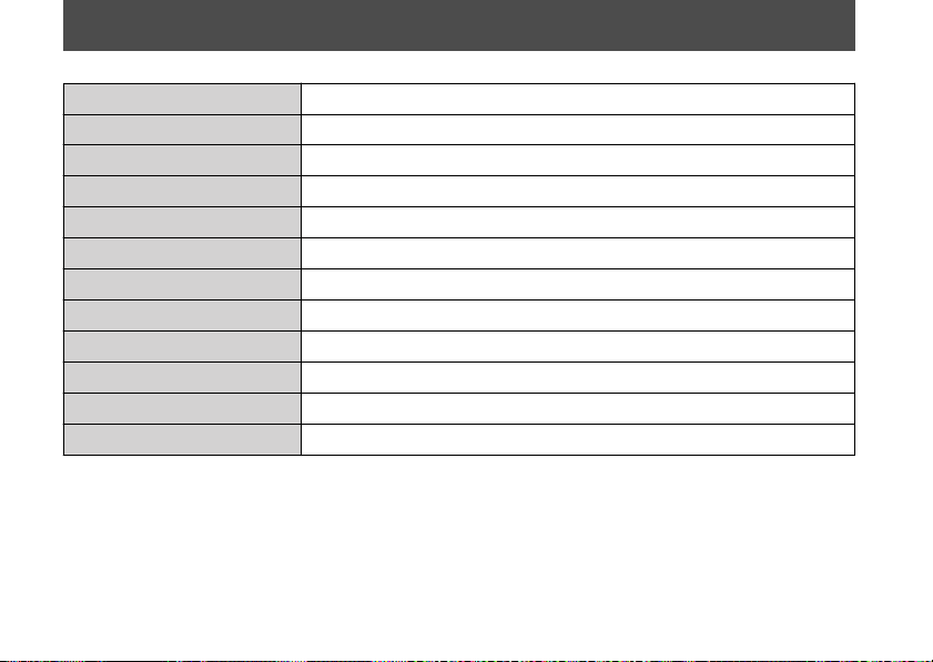
Information Record
VIN
Engine No.
Color Label & Code
Owner's Name
Address
City/State
Phone
Dealer's Name
Address
City/State
Phone
Service Manager
20170830152249_31MKF6100_enu_BOOK Page 229 Wednesday, August 30 2017 15:45:50 JST
226

Index
A
ABS (Anti-lock Brake System)....................... 13
ABS (Anti-lock Brake System)
Indicator
.................................................. 94, 182
Accessories........................................................ 16
B
Background....................................................... 63
Battery ..................................................... 123, 137
Battery Voltage ................................................ 40
Blank Display .................................................... 41
Brake Light Switch......................................... 151
Brakes
Fluid ........................................................... 130, 149
Lever Adjustment............................................. 163
Pad Wear........................................................... 150
Braking ............................................................... 12
Brightness ................................................. 62, 203
Bulb
Brake light/Taillight ......................................... 195
Front Turn Signal Light................................... 195
Headlight ........................................................... 194
License Plate Light........................................... 196
Rear Turn Signal Light .................................... 196
C
Caring for Your Motorcycle ........................ 203
Catalytic Converter........................................ 215
CBR Logo ........................................................... 40
Circuit Mode ..................................................... 24
Clear Data.......................................................... 57
Clock ................................................................... 22
Clutch System................................................. 157
Coolant .................................................... 132, 147
Coolant Temperature Gauge ........................ 26
D
Damping Adjustment ................................... 174
Date..................................................................... 41
Date & Time ...................................................... 70
Display
Background ......................................................... 63
Brightness ............................................................ 62
Display Mode...................................................... 59
Favorite................................................................. 65
Shift Indicator...................................................... 61
User Letter ........................................................... 64
Drive Chain...................................................... 153
DTC...................................................................... 84
20170830152249_31MKF6100_enu_BOOK Page 230 Wednesday, August 30 2017 15:45:50 JST
Index
227

E
EB Value ........................................................... 103
Electrical Trouble
........................................... 193
Engine
Number.............................................................. 210
Oil............................................................... 129, 143
Oil Filter.............................................................. 145
Overheats .......................................................... 180
Starting............................................................... 108
Stop Switch........................................ 99, 108, 201
Stopping...................................................... 99, 201
Will Not Start .................................................... 179
Environment ................................................... 209
Equipment
Owner’s Manual...................................... 113, 201
Tool Kit ............................................................... 113
F
Favorite .............................................................. 65
Flooded Engine .............................................. 108
Front Seat ........................................................ 139
Front Suspension .................................. 164, 170
Fuel
Recommended................................................. 111
Tank Capacity ................................................... 111
Fuel Mileage Meter ......................................... 75
Function
Quick Shifter........................................................ 46
Suspension A1, A2 and A3............................... 51
Suspension M1, M2 and M3............................ 52
Fuses......................................................... 129, 197
G
Gasohol ............................................................ 216
Gasoline ........................................................... 111
Gear Position Indicator .................................. 23
General
Date & Time........................................................ 70
Restore Default................................................... 76
Units ...................................................................... 71
H
Hazard Switch................................................... 98
Headlight Aim ................................................ 162
Headlight Dimmer Switch ............................. 98
Helmet Holder................................................ 112
HESD (Honda Electronic Steering
Damper) .................................................. 95, 182
20170830152249_31MKF6100_enu_BOOK Page 231 Wednesday, August 30 2017 15:45:50 JST
Index
228

High Beam Indicator....................................... 94
High Coolant Temperature
Indicator.................................................. 94,
180
Honda Contacts ............................................. 220
Horn Button ...................................................... 98
I
Ignition Cut-off System
Banking Sensor................................................. 202
Side Stand ......................................................... 152
Ignition Key..................................................... 200
Ignition Switch ................................ 99, 108, 201
Indicators........................................................... 93
INFO 1 Display .................................................. 28
INFO 2 Display.................................................. 31
INFO 3 Display.................................................. 39
Information Record....................................... 226
Instruments ....................................................... 22
L
Labels.................................................................... 8
LAP Button.................................................. 24, 98
Lap Data............................................................. 56
Lap Time
Clear Data............................................................ 57
Lap Data............................................................... 56
Lap Timer..................................................... 24, 86
Left Turn Signal Indicator.............................. 93
Lithium-Ion Battery....................................... 125
Load Limits........................................................ 17
Loading Guidelines.......................................... 17
Low Fuel Indicator........................................... 94
Low Oil Pressure Indicator.................... 93, 181
M
Maintenance
Fundamentals ................................................... 120
Importance........................................................ 115
Safety.................................................................. 116
Schedule ............................................................ 117
Maximum Weight Limit ................................. 17
Mechanic Mode ............................................... 60
Mileage .............................................................. 73
Modifications.................................................... 16
Multi-Information Display ...................... 23, 25
N
Neutral Indicator ............................................. 94
20170830152249_31MKF6100_enu_BOOK Page 232 Wednesday, August 30 2017 15:45:50 JST
Index
229

O
Odometer...............................................
... 29, 201
ÖHLINS Smart EC System............................ 170
Oil
Engine ....................................................... 129, 143
Overheating .................................................... 180
Oxygenated Fuels.......................................... 216
P
P Value ............................................................. 103
Parking ............................................................... 14
Parts Location................................................... 18
Passing Light Control Switch........................ 98
PGM-FI (Programmed Fuel Injection)
Malfunction Indicator Lamp (MIL).... 95, 181
Photosensor.................................................... 203
Pop-up Information
Failure ................................................................... 92
Helpful .................................................................. 91
Maintenance ....................................................... 91
Protective Apparel........................................... 10
Q
Quick Shifter ...................................... 46, 84, 110
Quick Shifter Indicator ................................... 23
R
Rear Seat.......................................................... 140
Rear Suspension.................................... 167, 170
Recommended
Coolant............................................................... 132
Fuel...................................................................... 111
Oil ........................................................................ 129
Refueling ......................................................... 111
Removal
Battery ................................................................ 137
Front Seat .......................................................... 139
Rear Seat............................................................ 140
Single Seat Cowl .............................................. 141
Under Cowl ....................................................... 142
Repair Kit ......................................................... 184
Reporting Safety Defects............................. 222
Restore Default ................................................ 76
Riding Mode ................................................... 101
Riding Precautions .......................................... 12
Right Turn Signal Indicator........................... 93
20170830152249_31MKF6100_enu_BOOK Page 233 Wednesday, August 30 2017 15:45:50 JST
Index
230

S
S Mode..........................................................
... 103
Safety Labels ....................................................... 8
Safety Precautions........................................... 10
Service
DTC........................................................................ 84
Maintenance ....................................................... 80
Quick Shifter........................................................ 84
Sports Kit ECU..................................................... 85
Suspension........................................................... 83
Setting Mode
Display ........................................................... 42, 58
Function......................................................... 42, 45
General .......................................................... 42, 69
Lap Time........................................................ 42, 55
Service............................................................ 42, 79
Sports Kit.............................................................. 42
Shift Indicator................................................... 61
Shift Indicator Set Value ................................ 40
Shift Indicators........................................... 93, 96
Shifting Gears................................................. 109
Side Stand ....................................................... 152
Side Stand Ignition Cut-off System .......... 152
Specifications.................................................. 223
Speedometer .................................................... 22
Sports Kit ECU .................................................. 85
Start Button .............................................. 99, 108
Starting the Engine ....................................... 108
Stopping Engine...................................... 99, 201
Storage
Equipment......................................................... 112
Owner’s Manual...................................... 113, 201
Tool Kit ............................................................... 113
Storing Your Motorcycle ............................. 207
Street Mode ...................................................... 22
Suspension ........................................................ 83
Suspension A1, A2 and A3............................. 51
Suspension M1, M2 and M3.......................... 52
Switches ............................................................. 98
T
T Value ............................................................. 103
Tachometer ....................................................... 22
Tachometer Red Zone.................................... 22
Temperature ..................................................... 74
Throttle.................................................... 161, 202
Throttle Grip Angle ......................................... 40
20170830152249_31MKF6100_enu_BOOK Page 234 Wednesday, August 30 2017 15:45:50 JST
Index
231

Tires
Air Pressure....................................................... 133
Puncture
............................................................. 184
Replacing.................................................. 133, 184
Torque Control Indicator............................... 93
Torque Control OFF Indicator....................... 93
Transporting Your Motorcycle................... 208
Tripmeter................................................... 29, 201
Troubleshooting ............................................ 178
Turn Signal Switch........................................... 98
U
Units.................................................................... 71
User Letter................................................... 41, 64
V
Vehicle Identification Number................... 210
W
Warranty Coverage and Service ................ 218
Washing Your Motorcycle........................... 203
Weight Limit ..................................................... 17
Wheels
Front Removal .................................................. 185
Rear Removal.................................................... 190
20170830152249_31MKF6100_enu_BOOK Page 235 Wednesday, August 30 2017 15:45:50 JST
Index
232
California Proposition 65 Warning
3WARNING
Operating, servicing and maintaining a passenger vehicle or off-
road vehicle can expose you to chemicals including engine
exhaust, carbon monoxide, phthalates, and lead, which are
known to the State of California to cause cancer and birth
defects or other reproductive harm. To minimize exposure, avoid
breathing exhaust, do not idle the engine except as necessary,
service your vehicle in a well-ventilated area and wear gloves or
wash your hands frequently when servicing your vehicle. For
more information go to
www.P65Warnings.ca.gov/passenger-vehicle.
20170830152249_31MKF6100_enu_BOOK Page 236 Wednesday, August 30 2017 15:45:50 JST