McIntosh Laboratory, Inc. 2 Chambers Street Binghamton, New York 13903-2699 Phone: 607-723-3512 www.mcintoshlabs.com
C2700
Tube Preamplifier
Owner’s Manual

2
Your decision to own this McIntosh C2700 Tube Pre-
amplifier ranks you at the very top among discrimi-
nating music listeners. You now have “The Best.” The
McIntosh dedication to “Quality,” is assurance that
you will receive many years of musical enjoyment
from this unit.
Please take a short time to read the information in
this manual. We want you to be as familiar as pos-
sible with all the features and functions of your new
McIntosh.
Copyright 2019 © by McIntosh Laboratory, Inc.
Table of Contents
Thank You
Please Take A Moment
Technical Assistance
If at any time you have questions about your McIntosh
product, contact your McIntosh Dealer who is familiar
with your McIntosh equipment and any other brands
that may be part of your system. If you or your Dealer
wish additional help concerning a suspected problem,
you can receive technical assistance for all McIntosh
products at:
McIntosh Laboratory, Inc.
2 Chambers Street
Binghamton, New York 13903
Phone: 607-723-3512
Fax: 607-724-0549
Customer Service
If it is determined that your McIntosh product is in
need of repair, you can return it to your Dealer. You
can also return it to the McIntosh Laboratory Service
Department. For assistance on factory repair return
procedure, contact the McIntosh Service Department
at:
McIntosh Laboratory, Inc.
2 Chambers Street
Binghamton, New York 13903
Phone: 607-723-3515
Fax: 607-723-1917
The serial number, purchase date and McIntosh Dealer
name are important to you for possible insurance
claim or future service. The spaces below have been
provided for you to record that information:
Serial Number: _______________________________
Purchase Date: _______________________________
Dealer Name: ________________________________
Safety Instructions .............................................................. 2
(Separate Sheet)..........................Important Additional
............................................Operation Information Guide
Thank You and Please Take a Moment .............................. 2
Technical Assistance and Customer Service ...................... 2
Table of Contents ................................................................ 2
General Information ........................................................... 3
Trademark and License Information .................................. 3
Connector and Cable Information ...................................... 3
Introduction ........................................................................ 4
Performance Features ......................................................... 4
Dimensions ......................................................................... 5
Installation .......................................................................... 6
Connections:
Rear Panel Connections, Connecting Components .........7-8
Rear Panel Connections (Separate Sheet) ...................Mc2B
Connecting Components (Separate Sheets) ...............Mc1A,
......................................................................... Mc1B, Mc2A
Input Assignment Chart (Separate Sheet) ................. Mc5A,
......................................................................................Mc5B
Vacuum Tube Power:
Switching Power On to the C2700 Preamplifier ................. 9
Important Safety Information is supplied in a separate document “Important Additional Operation Information Guide”
Remote Control:
HR085 Remote Control Push-buttons ............................... 10
How to use the HR085 Remote Control ............................ 11
Front Panel:
Front Panel Displays, Controls, Push-buttons
and Jack .............................................................................. 12
Setup:
How to Operate the Setup Mode ....................................... 13
Default Settings ................................................................. 13
Fir mware Version .............................................................. 13
Input Settings ..................................................................... 13
Rename Input ..................................................................... 14
Output Settings .................................................................. 15
Power Control Triggers 1, 2, 3 and 4 ................................. 16
Data Ports, Passthru, HDMI (ARC) and (CEC) ................ 17
Lip Sync Mode (ARC) and Digital Gain ........................... 18
Comm Port Baud Rate ....................................................... 19
Remote Control Codes, IR Sensor .................................... 19
Power Mode, Factory Reset .............................................. 20
Operation:
How to Operate the C2700 ................................................22
Trim, Bass and Treble Tone, Mode and Meter Lights .. 22-24
Tube Lights, Display Illumination, Phono Ajustments,
HXD Mode ........................................................................25
Mute, Tone Controls, Output 1&2, Trim, Output Meter
Passthru, Headphone Jack .................................................26
How to make a Recording, Optical and Coaxial Inputs
USB Input Operation and Driver Installation
and Installing the Software ............................................... 27
USB Connection, Windows Sound Setting
Control Panel Settings, USB Music Playback ................... 28
Reset of Microprocessors ..................................................29
Additional Information:
Specifications..................................................................... 30
Packing Instruction ............................................................ 31
3
General Information, Trademark and License Information, and Connector Information
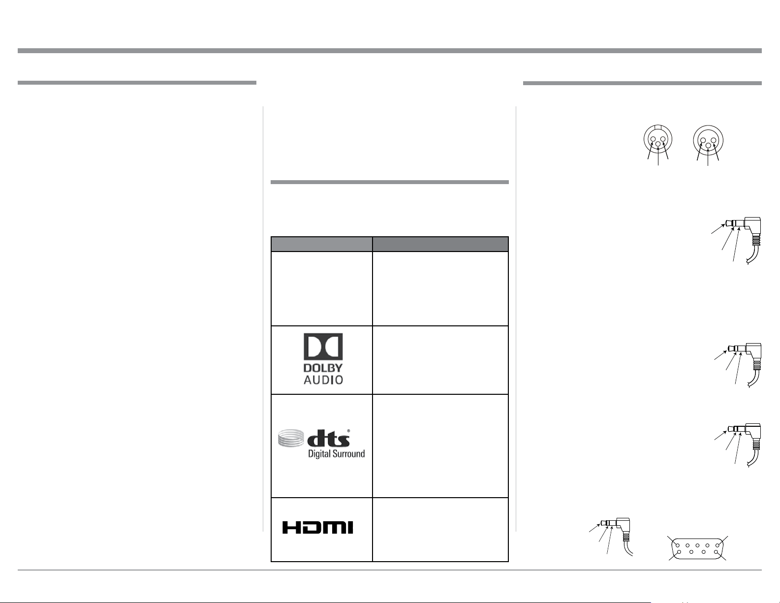
Connector and Cable Information
XLR Connectors
Pin configuration for the XLR Balanced Input and Out-
put Connector. Refer to the diagrams for connections:
PIN 1: Shield/Ground
PIN 2: + Input/Output
PIN 3: - Input/Output
Power Control and Trigger Connectors
The C2700 Power Control Out, Trigger and PASSTHRU
Output Jacks send Power On/Off Sig-
nals (+12 volt/0 volt) when connected
to other Components. An additional
connection is for controlling McIn-
tosh Power Amplifiers Output Meters.
A 3.5mm stereo mini phone plug is
used for connection to the Power Control (Trigger) and
PASSTHRU Output.
Note: The Six Foot Cables are available from the McIn-
tosh Parts Department. Part No. 170-202.
Data Port Connectors
The C2700 Data Out Ports send Re-
mote Control Signals to Source Com-
ponents. A 3.5mm stereo mini phone
plug is used for connection.
IR IN Port Connectors
The IR IN Port also uses a 3.5mm stereo
mini phone plug and allows the connec-
tion of other brand IR Receivers to the
C2700.
RS232 Data Port Cable
The RS232 Data Cable is a 3.5mm stereo mini phone
plug to a subminiature DB 9 connector:
Data
Signal
N/C
Data
Ground
PIN 2 PIN 1
PIN 3
PIN 1
PIN 2
PIN 3
1. Refer to pages 7-8 for component(s) connection to
the C2700 Preamplifier.
2. Do not apply AC Power to the C2700 and other
Component(s) until they are connected to the
C2700 so operational malfunctioning does not oc-
cur.
3. Balanced and Unbalanced Inputs and Outputs can
be mixed. For example, you may connect signal
sources to Unbalanced Inputs and send signals
from the Balanced Outputs. You can also use Bal-
anced and Unbalanced Outputs simultaneously,
connected to different Power Amplifiers.
4. The C2700 internal Digital to Analog Converter
Circuitry is designed to decode PCM, DSD and
DTS Digital Signals. The Coaxial and Optical
Digital Audio Inputs are for PCM Digital Signals,
Dolby Signals and DTS Signals. The C2700 also
decodes USB and HDMI (ARC) Digital Signals.
Other Digital Audio Signal Format Types will
cause the Audio Outputs of the C2700 to be muted
and the Front Panel Information Display will indi-
cate an error message.
5. The Audio Sound is measured in units called Deci-
bels and “dB” is the abbreviation.
6. The McIntosh C2700 is factory configured for im-
mediate use. It can also be customized to comple-
ment the components making up your system.
Refer to the C2700 “Setup Mode” starting on page
13 for additional information.
7. The Remote Control Supplied with the C2700 Pre-
amplifier is capable of operating other components.
For additional information go to www.mcintosh-
labs.com.
8. The IR Input is configured for non-McIntosh IR
sensors such as a Xantech Model HL85BK Kit. Use
a Connection Block such as a Xantech Model ZC21
when two or more IR sensors need to be connected
General Information
Power
Control
Meter
Illumination
Control
Ground
Main, Triggers 1-4
and PA SSTH RU
to the C2700. The signal from a connected External
IR Sensor will have priority over the signal from
the Front Panel IR Sensor.
9. For additional information on the C2700 and other
McIntosh Products please visit the McIntosh Web
Site at www.mcintoshlabs.com.
IR Data
Control
Ground
N/C
Data In
(DB9-pin2)
Ground
(DB9-pin5)
Data Out
(DB9-pin3)
PIN 1
PIN 6
PIN 5
PIN 9
DB9
(male connector)
The McIntosh C2700 incorporates copyright protected
technology that is protected by U.S. patents and other
intellectual property rights. The C2700 uses the fol-
lowing Technologies:
Trademark License Information
ASIO is a trademark and
software of Steinberg Media
Technologies GmbH
Manufactured under license
from Dolby Laboratories. Dolby,
Dolby Audio, and the double-D
symbol are trademarks of Dolby
Laboratories.
For DTS patents, see http://
patents.dts.com. Manufactured
under license from DTS, Inc.
DTS, the Symbol, DTS and
the Symbol together, and
Digital Surround are registered
trademarks and/or trademarks
of DTS, Inc. in the United
States and/or other countries.
DTS, Inc. All Rights Reserved.
The terms HDMI, HDMI
High-Denition Multimedia
Interface, and the HDMI Logo
are trademarks or registered
trademarks of HDMI Licensing
Administrator, Inc.
Trademark and License Information
HIGH-DEFINITION MULTIMEDIA INTERFACE
TM

4
Introduction
Performance Features
Introduction and Performance Features
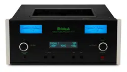
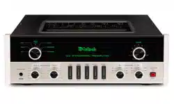
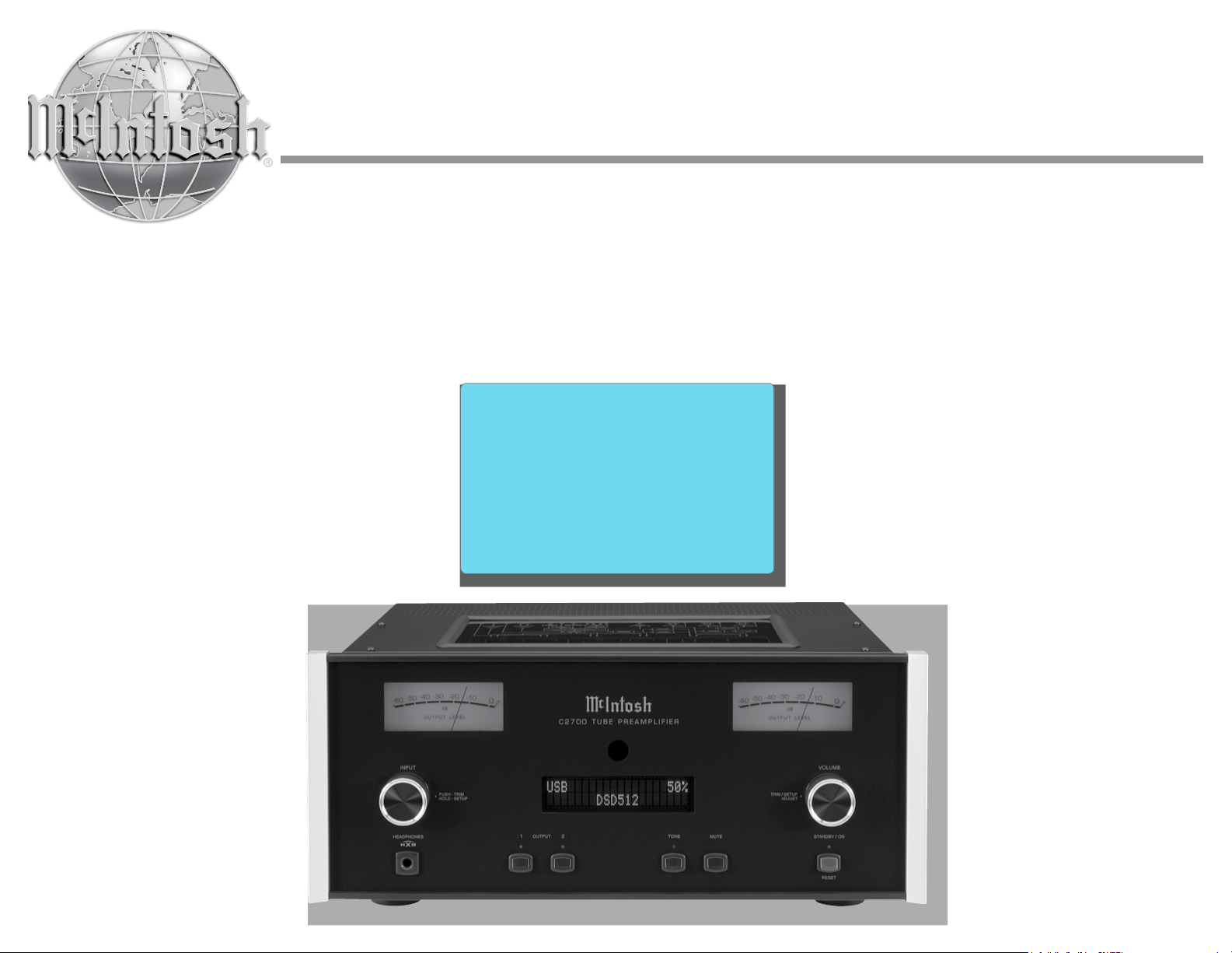
The McIntosh C2700 Tube Preamplifier is one of the
finest Preamplifiers ever created with connections for
both analog and digital sources. The C2700 Outputs
have the ability to drive multiple Power Amplifiers.
The C2700 reproduction is sonically transparent and
absolutely accurate. The McIntosh Sound is “The
Sound of the Music Itself.”
• Electromagnetic Input Switching with Level Trim
Adjustment
Digital Logic Circuits drive Electromagnetic Switches
on all Inputs and operating functions for reliable,
noiseless, distortion free switching. The Analog Inputs
can be matched in level, preventing abrupt changes in
volume levels.
• Moving Coil and Moving Magnet Phono Inputs
The C2700 has two precision Phono Preamplifier
Circuits, one for Moving Coil Phono Cartridges and
the other for Moving Magnet Cartridges. Both phono
inputs have selectable loading. The circuits use the
latest designs providing the lowest possible noise and
distortion. The close tolerance resistors and capacitors
used in the RIAA Correction Equalization Circuitry
provides an extremely flat frequency response.
• Digital Audio Inputs
The Digital Inputs decode PCM and DSD Signals
from external sources. Coaxial, Optical and HMDI In-
puts process Digital Signals up to 192kHz with 24-Bit
resolution. The Digital MCT Input Circuitry directly
decodes SACD/CD signals from an external Trans-
port component. The USB Input for streaming audio
processes Digital Signals up to 384kHz with 32Bit
resolution, decodes up to DSD512 Digital Signals and
DXD 24Bit with a sampling rate up to 384kHz.
• Balanced Inputs
The Balanced Inputs allow the connection of a source
component using long cable lengths without a loss in
sound quality.
• Precision Tracking Volume Control
Volume levels are controlled by a Precision Balanced
Digitally Controlled Attenuator System with an Opti-
cal Encoder Rotary Control. This assures a 0.1dB
tracking accuracy between channels. There are 214
individual 0.5dB volume level steps with no noise as
the volume level is changed.
• Variable Rate Volume and Balance Controls
The C2700 Preamplifier’s Volume and Balance Con-
trol Circuitry provides an ideal rate of change with
control rotation.
• Electronic Tone Controls with Bypass
Electronic Bass and Treble Circuitry allow volume
level adjustments for low and high frequencies in
precise one Decibel Steps. The C2700 remembers the
Tone Control Circuitry Bypass Option for each input.
• HXD
®
for Headphones
The C2700 Headphone Crossfeed Director Circuitry
(HXD
® )
improves the sound localization for Head-
phone Listening. HXD
TM
restores the directionality
component of the spatial sound stage normally heard
with Loudspeaker listening.
• Alphanumeric Fluorescent Display
The Front Panel Information Display indicates the
Source Selection, Volume/Balance Levels and Setup
Mode Selections. The display intensity is adjustable.
• PASSTHRU Mode
The Automatic PASSTHRU Mode allows the C2700
to become part of a Home Theater Multichannel
Sound System.
• Remote Control with External Sensor Input
The Remote Control provides control of the C2700
operating functions and McIntosh Source Components
connected to it. Enjoy your McIntosh System from
another room in your home by connecting an external
sensor.
• Power Control Output and Trigger Assignment
A Power Control connection for convenient Turn-On
of McIntosh Power Amplifiers, Source Components
and Accessories is included. The Power Control Trig-
ger Ouputs may be assigned to activate when a given
Input/Output is selected.
• Special Power Supply
Fully regulated Power Supplies and a special R-Core
Power Transformer ensure stable noise free operation
even though the power line varies.
• LED Front Panel Illumination
The even Illumination of the Front Panel is accom-
plished by multiple extra long life Light Emitting
Diodes (LEDs) arranged with a special orientation.
• Glass Front Panel and Super Mirror Chassis
Finish
The famous McIntosh Illuminated Glass Front Panel
and the Stainless Steel Chassis with Super Mirror
Finish ensures the pristine beauty of the C2700 will be
retained for many years.
HXD
®
is a registered trademark of McIntosh Laboratory, Inc.
5
Dimensions
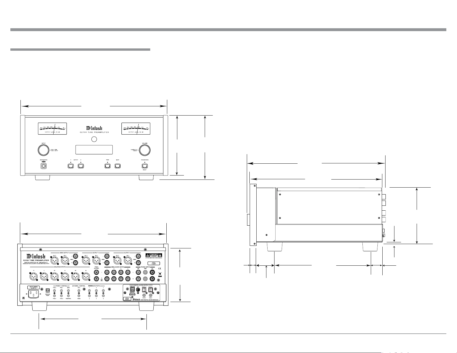
Dimensions
The following dimensions can assist in determining
the best location for your C2700. There is additional
information on the next page pertaining to installing
the C2700 into cabinets.
17-1/2"
44.5cm
6-3/8"
16.2cm
7-5/8"
19.4cm
13 -1/4"
33.7cm
17-1/8"
43.5cm
7-1/8"
18.1cm
16-1/2"
41.9cm
3/16"
0.5cm
13/16"
2.1cm
6-9/16"
16.7cm
10-9/16"
26.8cm
14-1/2"
36.8cm
2"
5.1cm
1-15/16"
4.9cm
Front View of the C2700
Rear View of the C2700
Side View of the C2700
USB 35%
DSD256
6
Installation
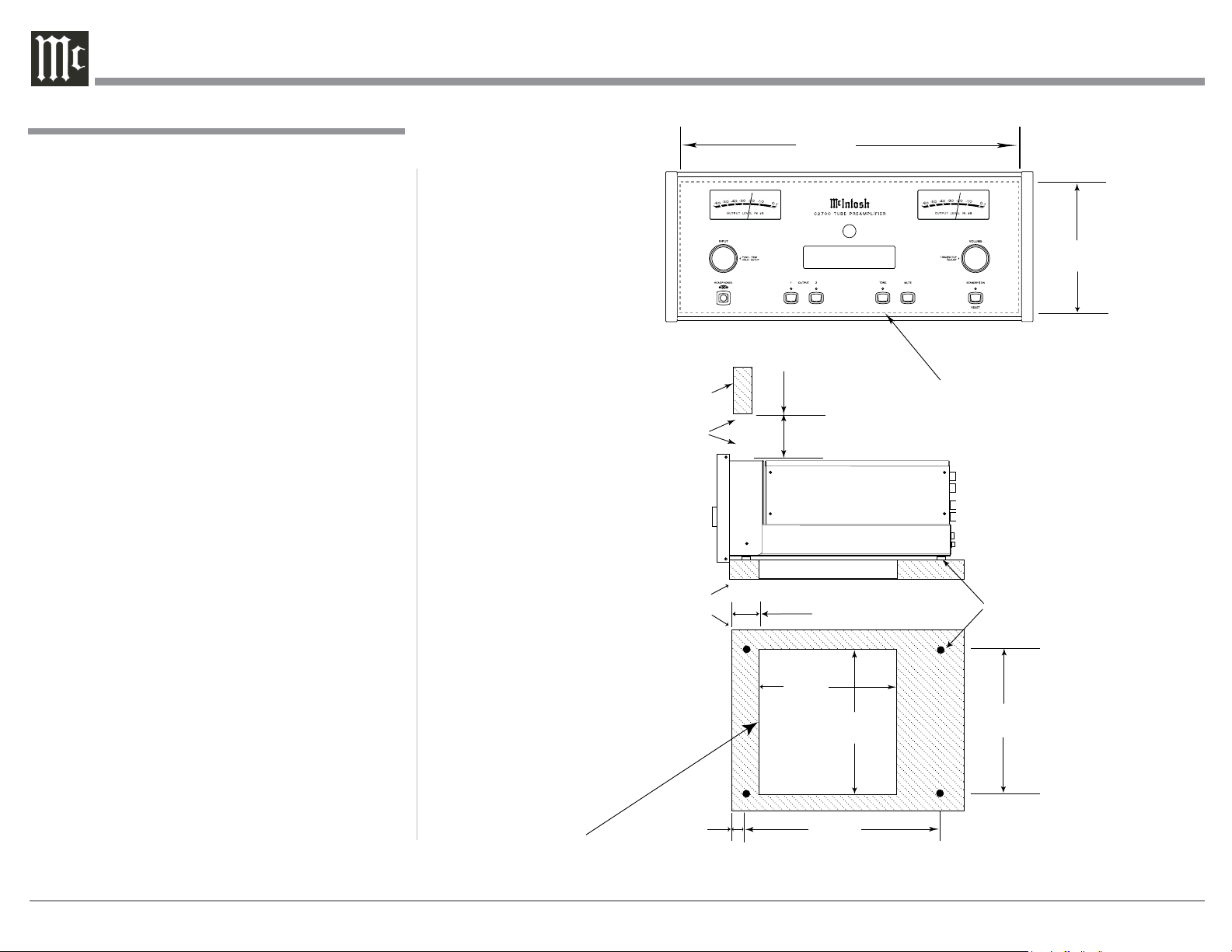
Installation
The C2700 can be placed upright on a table or shelf,
standing on its four feet. It also can be custom in-
stalled in a piece of furniture or cabinet of your
choice. The four feet may be removed from the bottom
of the C2700 when it is custom installed as outlined
below. The four feet together with the mounting
screws should be retained for possible future use if the
C2700 is removed from the custom installation and
used free standing. The required panel cutout, ventila-
tion cutout and unit dimensions are shown.
Always provide adequate ventilation for your
C2700. Cool operation ensures the longest possible
operating life for any electronic instrument. Do not
install the C2700 directly above a heat generating
component such as a high powered amplifier. If all
the components are installed in a single cabinet, a
quiet running ventilation fan can be a definite asset in
maintaining all the system components at the coolest
possible operating temperature.
A custom cabinet installation should provide the
following minimum spacing dimensions for cool
operation.
Allow at least 6 inches (15.2cm) above the top, 2
inches (5.1cm) below the bottom and 1 inch (2.5cm)
on each side of the Preamplifier, so that airflow is not
obstructed. Allow 20 inches (50.8cm) depth behind the
front panel. Allow 1-7/16 inch (3.7cm) in front of the
mounting panel for knob clearance. Be sure to cut out
a ventilation hole in the mounting shelf according to
the dimensions in the drawing.
6-5/8"
16.84cm
17-3/16"
43.66cm
Cutout Opening for Custom Mounting
C2700 Front Panel
Custom Cabinet Cutout
Cutout
Opening
for
Ventilation
Cutout Opening for Ventilation
Support
Shelf
Chassis
Spacers
C2700 Side View
in Custom Cabinet
12-5/16"
31.27cm
Note: Center the cutout Horizontally
on the unit. For purposes of
clarity, the above illustration
is not drawn to scale.
C2700 Bottom View
in Custom Cabinet
15"
38.10cm
9-1/8"
23.18cm
2-1/4"
5.72cm
15"
38.10cm
1-1/16"
2.70cm
USB 35%
DSD256
Cabinet
Front
Panel
6"
15.2cm
Opening
for Ventilation
7
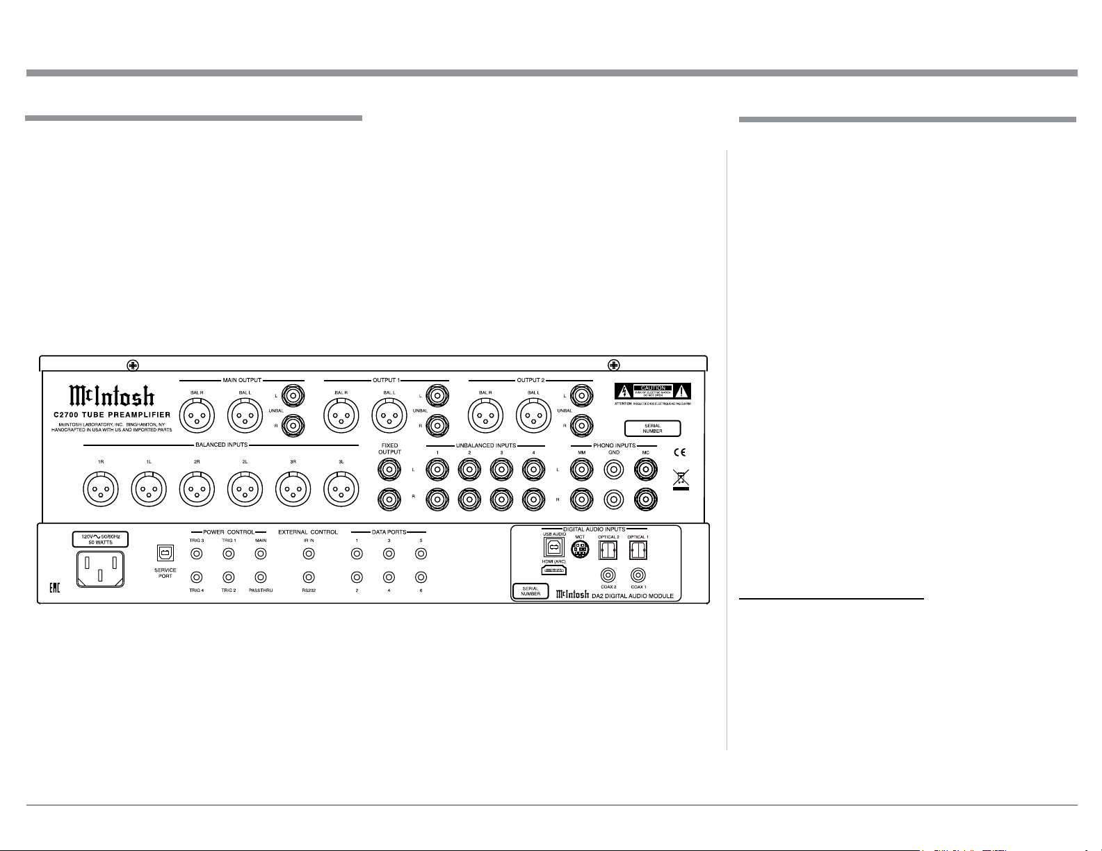
Connecting Components
The identification of Rear Panel Connections for the
C2700 Tube Preamplifier is located on a separate
folded sheet contained in the Owner’s Manual Packet.
Refer to separate sheet “Mc2B” for the Rear Panel
Connections.
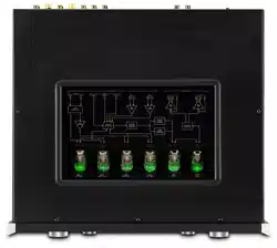
Rear Panel Connections
C2700 Audio Preamplifer Rear Panel
The C2700 has the ability to automatically switch
power On/Off to Source Components via the Power
Control connections. The Data Port Connections allow
for the remote operation of basic functions using the
C2700 Remote Control HR085. With an external sen-
sor connected to the C2700, remote control operation
of the system is possible from another room and/or
when the C2700 is located in a cabinet with the doors
closed.
The connection instructions below, together with
the C2700 Input/Output/Control Connection Diagrams
located on the separate folded sheets “Mc1A/1B and
Mc2A”, are an example of a typical audio system.
Your system may vary from this, however the actual
components would be connected in a similar manner.
For additional information refer to “Connector and
Cable Information” on page 3.
Notes: 1. The C2700 allows renaming of the Audio Inputs
Names as indicated on the Front Panel Infor-
mation Display. Example, “UNBAL 1” may be
changed to “TUNER” or your own personal
preference. Refer to Setup “Renaming Input” on
page 14.
2. For convenience, an “Input Assignment Chart”
on a separate sheet “Mc5A/5B” has been pro-
vided to keep track of changes.
Power Control Connections:
1. Connect a Control Cable from the C2700 POWER
CONTROL MAIN Jack to the Power Control In
on the Turntable.
2. Connect a Control Cable from the Turntable Pow-
er Control Out Jack to the Digital Audio Player
Trigger In Jack.
3. Connect a Control Cable from the Digital Audio
Player Trigger Out Jack to the SACD Transport
Power Control In Jack.

8
Rear Panel Connections and Connecting Components
4. Connect a Control Cable from the SACD Trans-
port Power Control Out Jack to the Tuner Power
Control In Jack.
5. Connect a Control Cable from the Tuner Power
Control Out Jack to the Media Bridge Pwr Ctrl
(Power Control) In Jack.
6. Connect a Control Cable from the C2700 POWER
CONTROL TRIG (Trigger) 1 Jack to the Power
Amplifier Power Control In Jack.
Notes: 1. If two separate Power Amplifiers are used
(Left and Right Channels), connect the Power
Control Output of the first Amplifier to the
Power Control Input on the second Amplifier.
2. By the defaut settings, POWER CONTROL
Triggers 1 and 2 will be active when the
C2700 OUTPUT 1 and/or 2 is selected by the
Front Panel or Remote Control Push-buttons.
7. Optionally, connect a Control Cable from the
C2700 POWER CONTROL TRIG (Trigger) 2 Jack
to the Power Amplifier (Secondary Room) Power
Control In Jack.
8. Connect any additional Components in a similar
manner, as outlined in steps 1 thru 5.
Data Control Connections:
9. Connect a Control Cable from the C2700 DATA
PORTS 2 Jack to the TUNER Data In Jack.
Note: To have source components (e.g. Tuner) respond
only to their specific “Function Commands”
issued by the Remote Control, it is first neces-
sary to change the Data Ports Default settings
for the “Tuner” Input. Refer to Setup “Data Port
Assignment”on page 16.
10. Connect a Control Cable from the C2700 CD
DATA PORT 3 Jack to the SACD/CD Transport
Data In Jack.
11. Connect a Control Cable from the C2700 DATA
PORT 1 Jack to the Media Bridge Data In Jack.
12. Connect any additional McIntosh Components in a
similar manner, as outlined in steps 9 thru 11.
Sensor Connection:
13. Connect a Control Cable from the C2700 IR Input
Connector to the external Sensor. For additional
information, refer to “General Information” note 8
on page 3.
Audio Connections:
14. Connect an Audio Cable from the C2700 UN-
BALANCED INPUT 1 (Tuner) Jacks to the Tuner
Unbalanced Output Jacks.
15. Using the “DIN Cable-Twisted Pair” cable (sup-
plied with a MCT Transport) from the C2700 MCT
DIGITAL AUDIO INPUT connector to the SACD/
CD Transport DIN Output connector.
16. Connect an XLR Audio Cable from the C2700
BALANCED INPUT 1 connectors to the Media
Bridge Balanced Output connectors.
17. Connect a Digital Coaxial Cable from the C2700
DIGITAL AUDIO INPUT COAXIAL 1 Jack to
the Digital Audio Player Digital Coax Output Jack.
18. Connect the Audio Cables coming from the Turn-
table to the C2700 MC PHONO INPUT Jacks.
Note: If the Turntable has a Moving Magnet Car-
tridge, connect the audio cables to the C2700
MM PHONO INPUT instead of the MC Input.
19. Connect XLR Audio Cables from the C2700 BAL-
anced OUTPUT 1 connectors (Left and Right) to
the Power Amplifiers (Primary Room) Balanced
(Left and Right) Inputs.
20. Optionally, connect Audio Cables from the C2700
UNBalanced OUTPUT 2 connectors (Left and
Right) to the Power Amplifier (Secondary Room)
UNBalanced (Left and Right) Inputs.
21. Connect any additional McIntosh Components in a
similar manner, as outlined in steps 14 thru 20.
Optional “PassThru” Connections:
22. Connect XLR Audio Cables from the A/V Pro-
cessor, Front Channels (Left and Right) Balanced
Output connectors to the C2700 BALANCED
INPUT 3 connectors.
Note: Refer to Setup “PASSTHRU” on page 17 to acti-
vate the BALANCED 3 Input.
23. Connect a Control Cable from the C2700
PASSTHRU Jack to A/V Processor Power Control
Zone ZA Jack.
Optional USB Connection:
24. Connect a USB cable with (Type A to Type B)
connectors from the C2700 USB DIGITAL AU-
DIO INPUT connector to an available USB con-
nector on the computer.
Optional HDMI (ARC) Connection:
25. Connect a HDMI cable with connectors from the
C2700 HDMI (ARC) DIGITAL AUDIO INPUT
connector to an available HDMI (ARC) connector
on the TV/Monitor.
Ground Connections:
26. Connect the Ground Cable coming from the Turn-
table to the C2700 PHONO INPUT GND Binding
Post.
AC Power Cord Connections:
27. Connect the C2700 to a live AC Outlet using the
supplied Power Supply Cord.
9
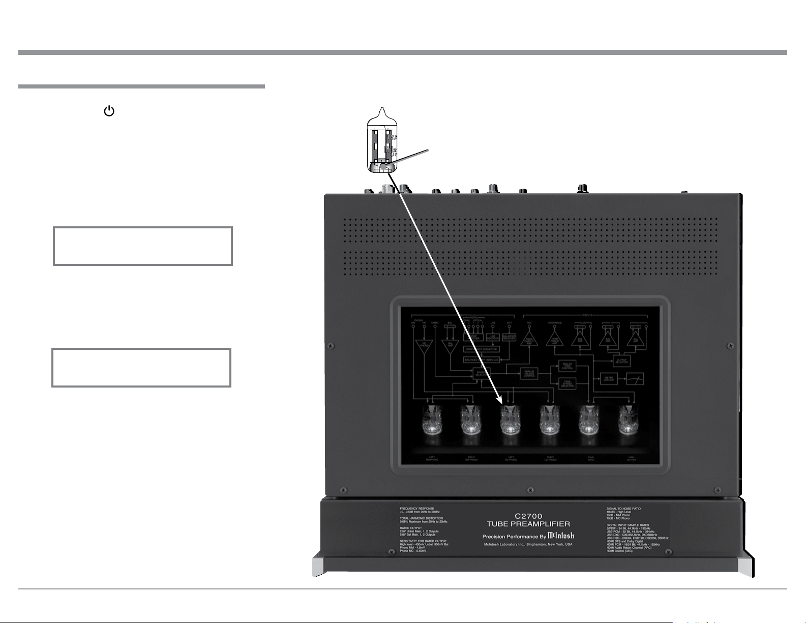
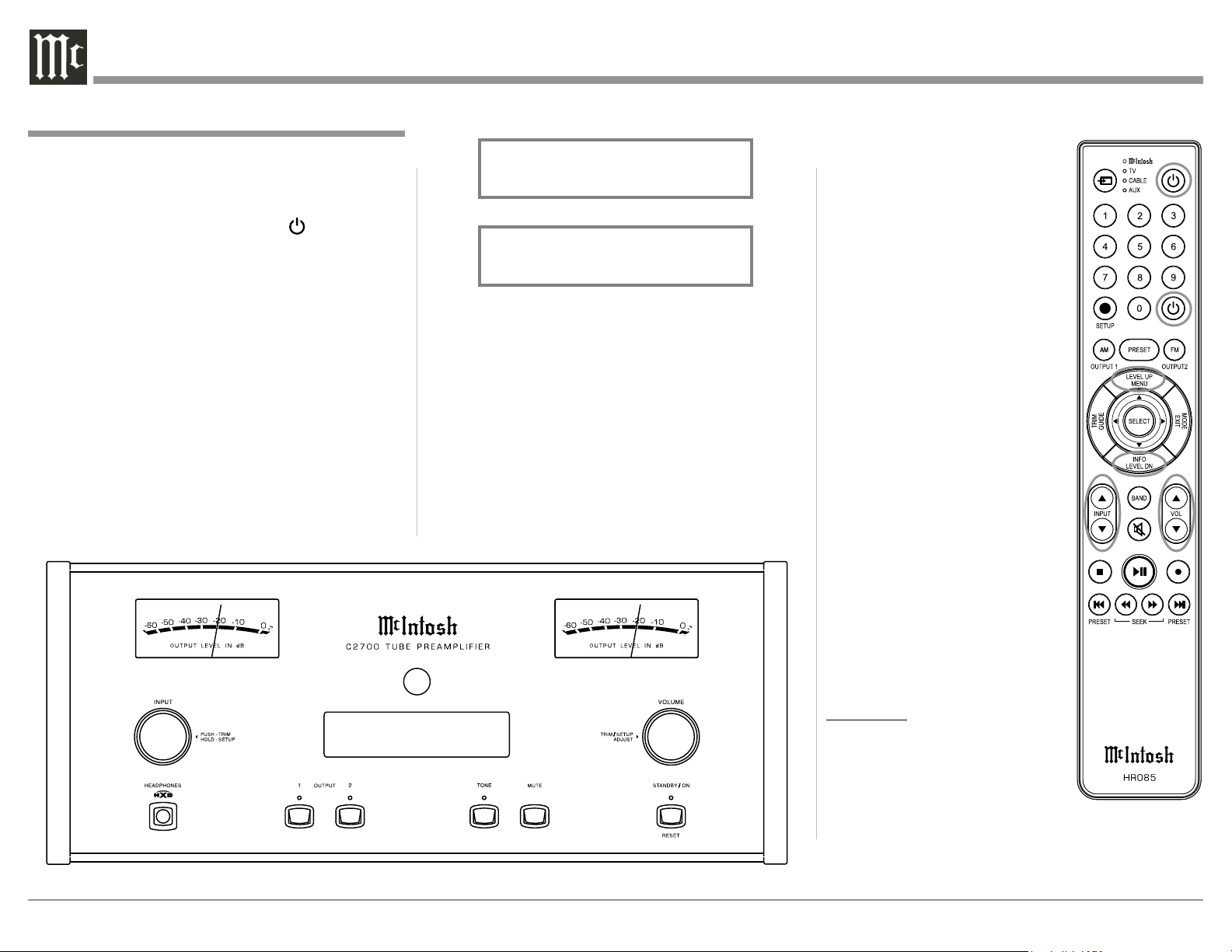
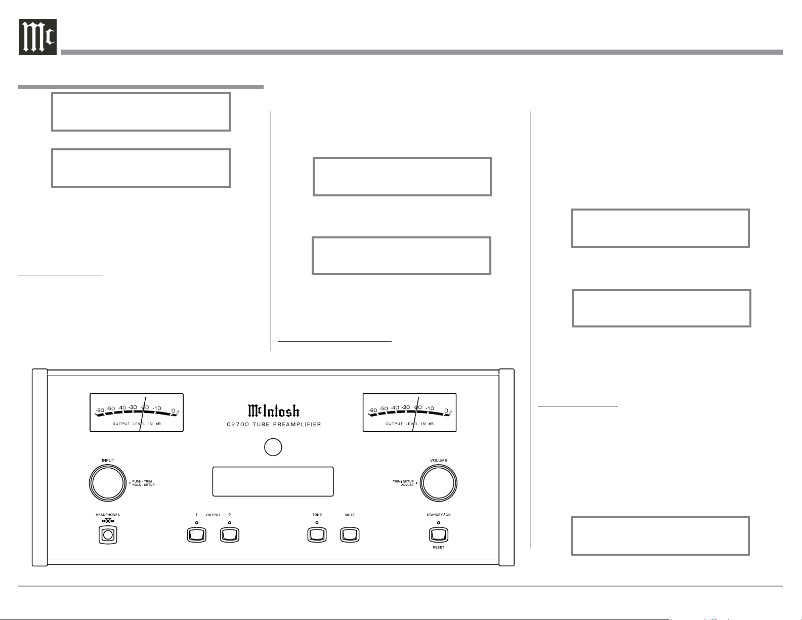
Press the STANDBY/ON Push-button on the Front
Panel or press the (Power ON) Push-button on
the Remote Control to switch On the C2700. The
C2700 will go through a TUBE WARMUP cycle (15
seconds), with the Audio Muted. Refer to illustration
figure A.
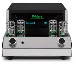
Referring to Figure B, the Tubes in the C2700 glow an
amber color and a brief startup initialization with the
Front Panel Information Display indicating “C2700,
TUBE WARMUP”. Refer to figure B.
The illumination of the Tubes will now glow a green
color; this is followed by the last Input Source listened
to and the volume setting indication starting at zero
and then increasing to the last used volume setting.
Refer to figure C.
Switching Power On to the C2700 Tube Preamplifer
C2700 Switch Power On
LED Illumination Color:
Orange - Warmup Mode and
Green - Normal Operation
Preamplifier Small Signal
Vacuu m Tube
Figure B
C2700
Tube Warmup
Figure C
BAL 1 15%
Figure A
10
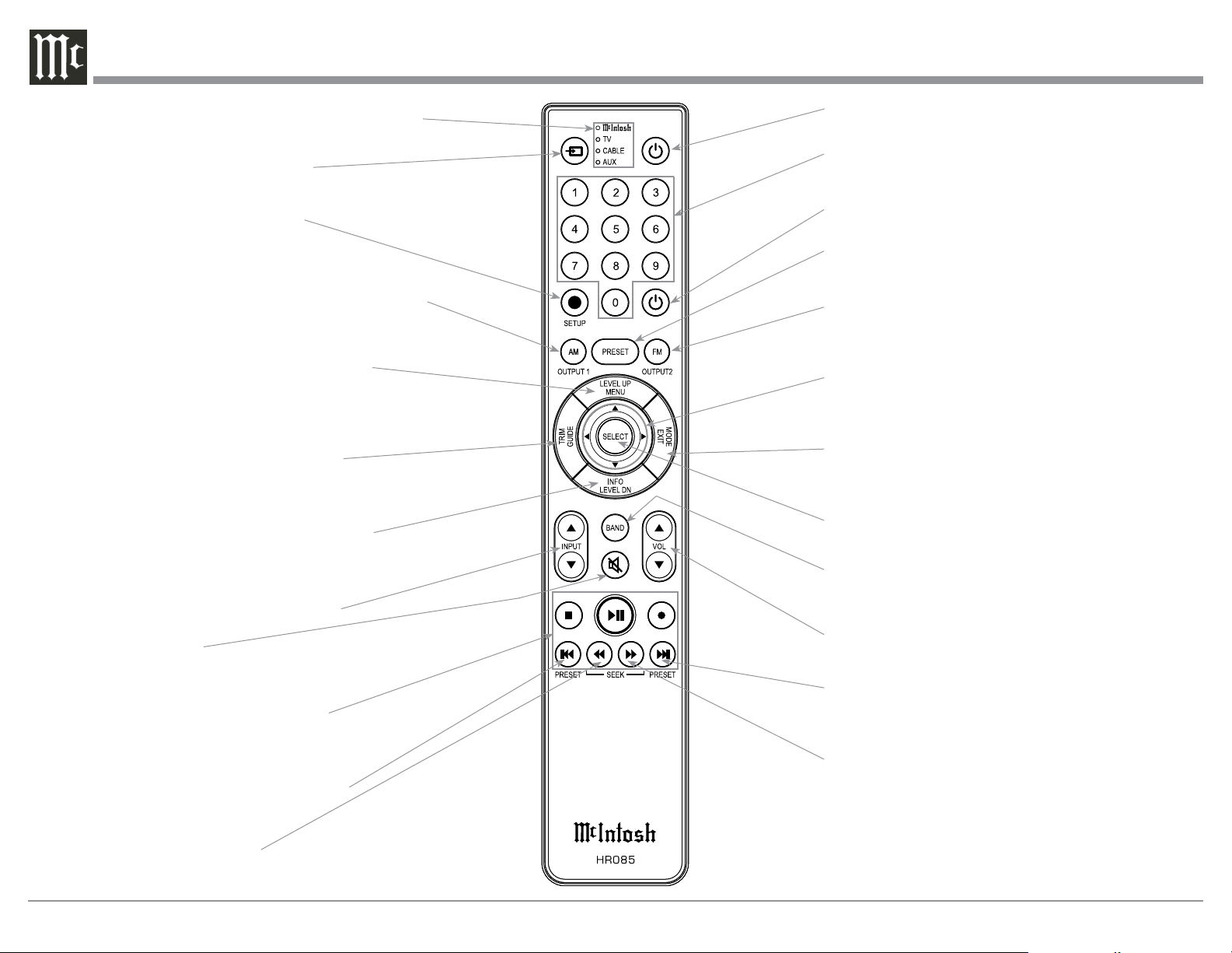
Note: Push-buttons whose function is not identified
above are for use with other McIntosh Products.
Press to Power the Preamplifier ON
Use to select tuner presets, direct ac-
cess an AM/FM Station Frequency,
disc tracks or any numbered operation
Mutes the audio
Adjusts the VOLume level up or down
Selects FM Tuner Operating Functions, select Output
2 when used with the SETUP/shift Push-button and
Track Selection on certain McIntosh CD Players
LEDs illuminate during the time a remote command
is sent and when programming the remote control
Press the Trim Push-button and then the
LEVEL UP Push-button to select and adjust
various functions. MENU is used with Mc-
Intosh Models displaying choices on a video
screen
Scrolls through the available INPUTS
Used to SELECT/Enter the indicated choice
Use p and q to tune Up or Down the AM/FM
Dial, use u and t for the next or previous HD
Radio Program (were applicable)
Activates the TRIM Mode. GUIDE is
used with McIntosh Models displaying
instructions on a video screen
Press to change broadcast bands on a
connected Tuner. Select certain functions
on a variety of McIntosh Models
Select the DEVICE to issue a remote
control command to
Direct access to stored Tuner PRESETS when
used with the numeric Push-buttons (0 thru 9)
Press the Trim Push-button and then the
LEVEL DOWN Push-button to select and
adjust various functions. INFO is used with
McIntosh Models displaying information on
a video screen
Selects transport functions of STOP,
PLAY/PAUSE, RECORD, BACK for
the previous-selection, FAST-RE-
VERSE, FAST-FORWARD and NEXT
for the next selection
Selects Previous Tuner Station PRESET
Tuner scans Down the dial
to SEEK the next Station
Selects Next Tuner Station PRESET
Tuner scans Up the dial to
SEEK the next Station
EXIT the TRIM Menu and is used with McIntosh
Models displaying information or choices on a video
screen
SETUP Push-button is used as a
“Shift Key” to select a function
with blue color nomenclature
HR085 Remote Control Push-Buttons
Selects AM Tuner Operating Functions, select Output
1 when used with the SETUP/shift Push-button and
Track Selection on certain McIntosh CD Players
Press to Power the Preamplifier OFF

11
How to use the HR085 Remote Control
How to use the Remote Control
The supplied C2700 Remote Control (HR085) is ca-
pable of directly controlling the functions of contem-
porary McIntosh Source Components connected to the
C2700 via the Data Ports.
Notes: 1. If at any time the C2700 seems unresponsive
to the HR085 Remote Control Commands,
press the DEVICE Push-button to select
first.
2. For additional information on using the
HR085 Remote Control with the McIntosh
Model, please refer to the “How to Operate”
starting on page 22.
3. For additional information on assigning the
Data Ports, refer to “How to Setup” on page
13.
Trim
Press the TRIM Push-button until the desired Trim
function (Balance, Trim Level, etc.) appears on the
C2700 Front Panel Display, then press the LEVEL Up
or Down Push-button to adjust the Trim setting.
Note: Press the TRIM Push-button to recall the last Trim
function selected. For additional information on
using the Trim Functions refer to “How to Oper-
ate” pages 22-26.
Output Selection
Press the BLUE (Setup) Push-button followed by
the AM (Output 1) or FM (Output 2) Push-button, to
control the Rear Panel Audio OUTPUTS 1, 2 (ON or
OFF) and Power Control TRIG 1 / TRIG 2.
Note: For additional information on assigning the Out-
puts (1 and 2) and Power Control Triggers (1 and
2) refer to page 16.
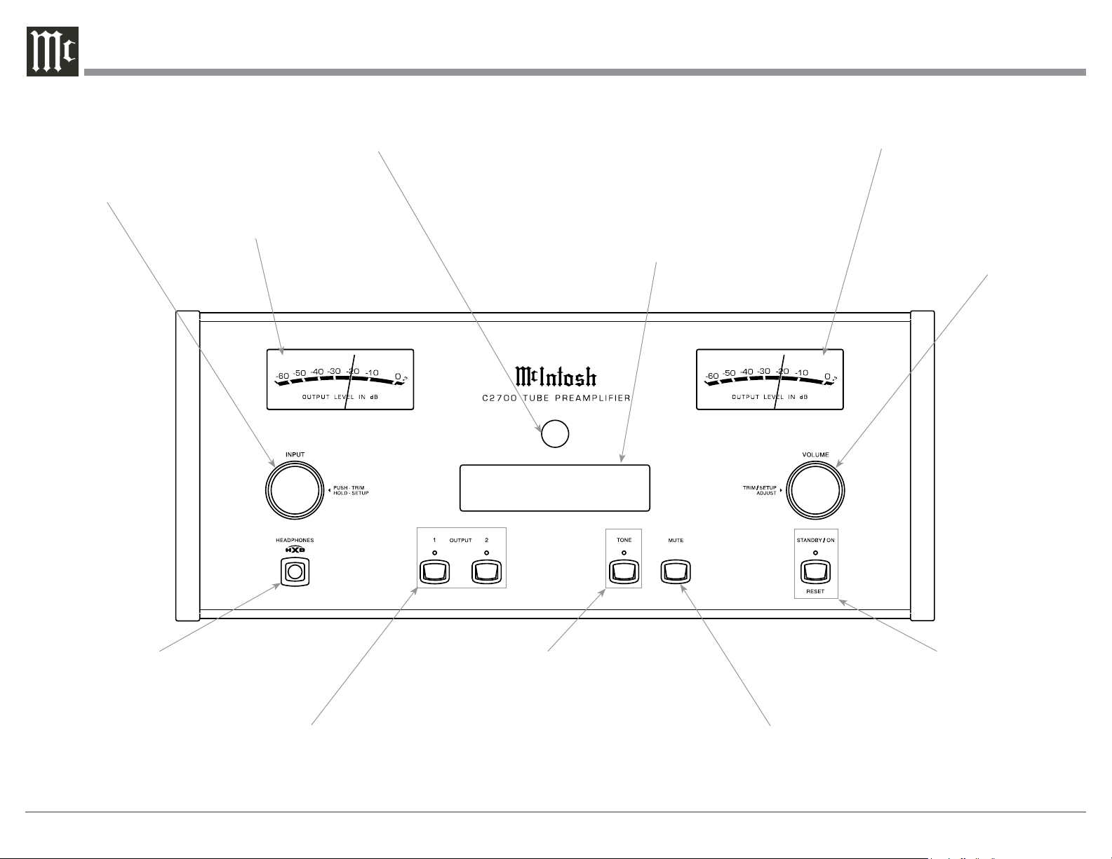
12
USB 35%
DSD256
IR Sensor receives
commands from a
Remote Control
STANDBY/ON Push-button
with indicator, switches the
C2700 ON or OFF (Standby)
and resets the microprocessors
VOLUME Control allows ad-
justment of the listening level
for both channels. Also used
to change the various TRIM
and SETUP Functions
Connection for low impedance
dynamic headphones, for private
listening
MUTE Push-button mutes
the audio from the Loud-
speakers and Headphones
INPUT Control used to
select a source for listening
and recording. The control is
also used to enter the TRIM
or SETUP Modes and select
the various functions
Meter indicates the
Right Channel Output
of the Preamplifier
Meter indicates the
Left Channel Output
of the Preamplifier
OUTPUT 1 and 2 Push-buttons
with indicators, switch the
Preamplifier Outputs 1 and 2
On or Off
INFORMATION DISPLAY indicates
the Sources, Volume, other Audio
Settings, Operational Functions and
Setup Mode Settings
Front Panel Displays, Controls, Push-buttons and Jack
TONE Push-button with indicator,
push to activate the Tone Control
Circuitry for the current Input
Source
13
the Setup Mode.
1. Press and hold in the INPUT Control to enter
Setup Mode.
2. Referring to the Front Panel Information Display-
the number after the character “V” is the Firm-
ware number. Refer to figure 2.
To view the second Firmware Number, which is for
the Digital Audio Circuitry of the C2700, perform the
following steps:
3. Press and hold in the INPUT Control to enter
Setup Mode.
4. Rotate the INPUT Control until the Front Panel
Information Display indicates “DA2 Firmware,
V1.00” (or higher Digital Audio Firmware ver-
sion). Refer to figure 4.
5. To exit the Setup Mode, press the INPUT Control.
4. To exit from the SETUP Mode, press and hold in
the INPUT Control and the Front Panel Display
will revert back to its normal display. Refer to
figure 1.
Your McIntosh C2700 has been factory configured for
default operating settings that will allow immediate
enjoyment of superb audio without the need for fur-
ther adjustments. If you wish to make changes to the
factory default settings, a Setup Feature is provided to
customize the operating settings using the Front Panel
Information Display. Refer to the C2700 Front Panel
Illustration on the previous page while performing the
following steps.
Note: If the C2700 is currently On, proceed to step 2.
1. Press the STANDBY/ON Push-button on the Front
Panel or press the (Power ON) Push-button on
the Remote Control to switch On the C2700. Refer
to page 9 for information about Switching Power
On to the C2700. After the C2700 goes through
its startup, the Front Panel Information Display
indicates the last used source and volume setting.
This is followed by the volume setting indication
starting at zero and then increasing to the last used
volume setting. Refer to figure 1.
2. Press and hold in the INPUT Control until the
Front Panel Information Display indicates “C2700,
V1.00 - S/N: AHM____” (or higher Firmware
version). Refer to figure 2.
3. Rotate the INPUT Control to select the next
Setup Mode Menu item, “SETUP: Inputs, (Hold
INPUT)”. Refer to figure 3. Continue to rotate
the INPUT CONTROL to view the other SETUP
Mode Options.
How to Operate the Setup Mode
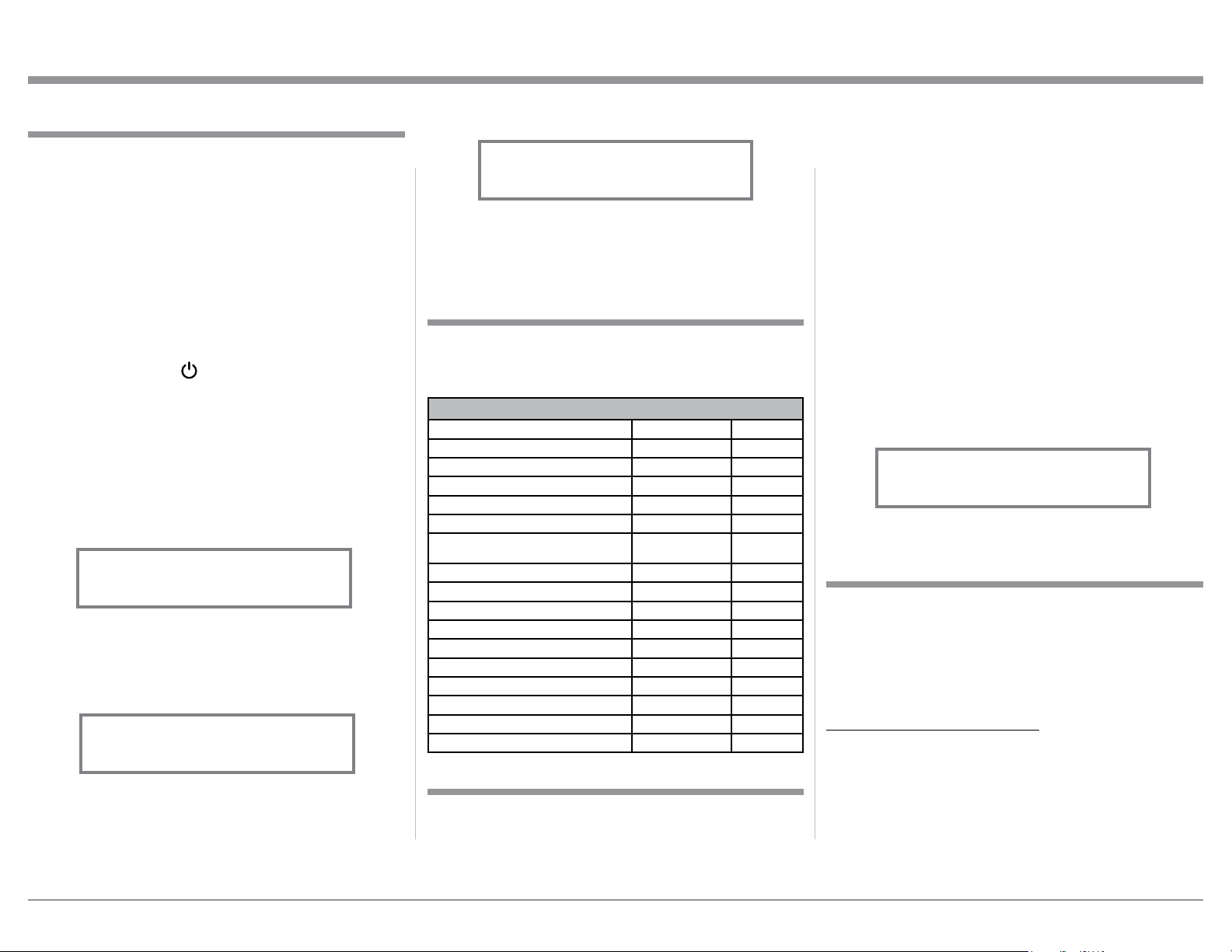
The Default Settings Chart below indicates the Func-
tion Name, Default Setting and the Page Number for
additional information.
Default Settings
Firmware Version
Setup
Figure 2
C2700 V1.00
S/N: AHM____
Figure 1
BAL 1 15%
The C2700 provides the ability to switch unused
INPUTS Off (or back On if they have been previously
switched Off). The default INPUT Names can be
changed to match the name of the component con-
nected to it or any other custom name desired (within
10 Characters).
INPUT SWITCHED ON/OFF:
In the following example, the UNBAL 4 Input will be
switched Off.
Note: When an INPUT is swiched Off, its name will
no longer appear on the Front Panel Informa-
tion Display when using the INPUT Control
(Front Panel or Remote Control).
1. Press and hold in the INPUT Control to enter the
SETUP MODE. Refer to figure 3.
Input Settings
Figure 3
SETUP: Inputs
(Hold INPUT)
Default Settings
Function Name Setting Page No.
C2700 V1.00 13
DA2 V1.00 13
INPUTS On / Rename 13-15
OUTPUTS (1 & 2 & Headphones) Switched 15
POWER CONTOL TRIGGERS Various Settings 16
DATA PORTS
(1 thru 4)
All Data 16
PASSTHRU OFF 17
HDMI CEC (Consumer Electronic Control) Control Command 17
HDMI CEC Power Power On or Off 17
Lip Synchronize Mode (Video and Audio) Activate or Deactivate 18
Digital Gain (for HDMI, Optical 1 & Optical 2) Input Comparison 18
Comm Port Baud Rate 115200 Baud 18
Remote Control Codes Normal 19
IR Sensor Enabled 19
Power Mode Enabled 19
Factory Reset Default Settings 20
Figure 4
DA2 FIRMWARE
V1.00
The C2700 functionality is controlled by internal
software that is know as Firmware. There are two
Firmware Identification Numbers for the C2700. The
first Firmware Number is for the Main Circuitry of the
C2700 and can be identified at any time by utilizing
14
Input Settings, con’t
Display. The character “B” is flashing to indicate
it is ready to be changed. Refer to figure 9.
15. Rotate the VOLUME (ADJUST) Control to change
the character “B” to “M”. Refer to figure 10.
16. Rotate the INPUT Control until the character “A”
is flashing, then rotate the VOLUME (ADJUST)
Control to change the character “A” to “E”. Refer
to figure 11.
17. Rotate the INPUT Control until the character “L”
is flashing, then rotate the VOLUME (ADJUST)
Control to change the character “L” to “D”. Refer
to figure 12.
18. Rotate the INPUT Control until the “_” empty
space to the right of character D is flashing, then
rotate the VOLUME (ADJUST) Control to change
the “_” empty space to character to “I”. Refer to
figures 13 and 14.
2. Rotate the INPUT Control until “SETUP: Inputs,
(Hold INPUT)” appears on the Information Dis-
play. Refer to figure 3 on page 13.
3. Press and hold in the INPUT Control until “SET-
UP: UNBAL 3, On/Name (Hold INPUT)” appears
on the Display. If necessary rotate the INPUT Con-
trol to select the UNBAL 3 Input. Refer to figure 5.
4. To switch the UNBAL 3 Input Off, rotate the
VOLUME Control Counterclockwise until the
display indicates “SETUP: UNBAL 3, Off”. Refer
to figure 6.
5. Exit the SETUP Mode by several presses of the
INPUT Control.
In the following example, the UNBAL 3 Input will be
switched On.
Notes: 1. When an INPUT is switched ON, its name will
appear on the Front Panel Information Display
when using the INPUT Control (Front Panel or
Remote Control).
6. Press and hold in the INPUT Control to enter the
SETUP MODE. Refer to figure 2, on page 13.
7. Rotate the INPUT Control until “SETUP: Inputs,
(Hold INPUT)” appears on the Information Dis-
play. Refer to figure 3, on page 13.
8. Press and hold in the INPUT Control until “SET-
UP: UNBAL 3, Off” appears on the Display. If
necessary rotate the INPUT Control to select the
UNBAL 3 Input. Refer to figure 6.
9. To switch the UNBAL 3 Input On, rotate the VOL-
UME Control until the display indicates “SETUP:
UNBAL 3, On / Rename”.
10. Exit the SETUP Mode by several presses of the
INPUT Control.
R ENA ME I NPU T:
In the following example, the BALANCED 1 (BAL
1) Input will be renamed to match up with the compo-
nent connected (refer to page 8, step 16).
The C2700 Default Input Names (UNBAL 1, BAL 1,
COAX 1, etc.) as indicated on the Front Panel Dis-
play can be customized to a different name up to ten
characters long (TUNER, CD PLAYER, etc.). The
available characters for renaming the input include the
following: ! < > * , / - _ 0 1 2 3 4 5 6 7 8 9 A B C D E
F G H I J K L M N O P Q R S T U V W X Y Z .
In the following example, the BAL 1 Input will be
renamed to “MEDIA BRDG”.
11. Press and hold in the INPUT Control to enter the
SETUP MODE. Refer to figure 2, on page 13.
12. Rotate the INPUT Control until “SETUP: Inputs,
(Hold INPUT)” appears on the Information Dis-
play. Refer to figure 7.
13. Press and hold in the INPUT Control until “SET-
UP: BAL 1, On/Name (Hold INPUT)” appears on
the Display. If necessary rotate the INPUT Control
to select the BAL 1 Input. Refer to figure 8.
14. Press and hold in the INPUT Control until “RE-
NAME: BAL 1, >BAL 1 < ” appears on the
Figure 6
SETUP: UNBAL 3
Off
Figure 8
SETUP: BAL 1
On/Name (Hold INPUT)
Figure 10
RENAME: BAL 1
>MAL 1 <
Figure 12
RENAME: BAL 1
>MED 1 <
Fig u re 11
RENAME: BAL 1
>MEL 1 <
Figure 7
SETUP: Inputs
(Hold INPUT)
Figure 9
RENAME: BAL 1
>BAL 1 <
Figure 13
RENAME: BAL 1
>MED <
Figure 5
SETUP: UNBAL 3
On/Name (Hold INPUT)
15
Setup, con’t
19. Repeat steps 15 thru 18 until the new name of
“RENAME: BAL 1, MEDIA BRDG” is indicated
on the Front Panel Display. Refer to figures 13 thru
20.
20. To save the new name, press and hold in the IN-
PUT Control until “SETUP: MEDIA BRDG , ON
/ Name (Hold INPUT)” appears on the Front Panel
Information Display. Refer to figure 21.
4. Rotate the VOLUME (ADJUST) Control to change
from the “Switched” setting to “Unswitched”.
Refer to figure 23.
5. In a similar manner, perform steps 3 and 4 to
change the OUTPUT 2 setting. Refer to figures 24
and 25.
The C2700 Default Setting for using Headphones is to
automatically mute all the Output Connectors when
the Headphone Cable Plug is inserted into the C2700
Front Panel HEADPHONES Jack. There are two
available settings:
Mute All Outputs
Mute No Outputs
6. Rotate the INPUT Control until “SETUP: HEAD-
PHONES, Mute All Outputs ” appears on the
Information Display. Refer to figure 26.
7. Rotate the VOLUME (ADJUST) Control to change
the current HEADPHONES setting from “SETUP:
HEADPHONES, Mute No Outputs”. Refer to
f igures 27.
Figure 15
RENAME: BAL 1
>MEDIA <
Figure 14
RENAME: BAL 1
>MEDI <
The Output Settings provide the ability to change how
the C2700 Output 1, Output 2 and Headphones func-
tion.
OUTPUT 1 and 2:
By defaut OUTPUT 1 and 2 are set to go On/Off by
using the Front Panel OUTPUT 1 and 2 Push-buttons
or by using the OUTPUT 1 and 2 Push-buttons on the
Remote Control. If it is desirable to have OUTPUT 1
and/or 2 always On regardless of the OUTPUT 1 and
2 Push-button settings, perform the following:
1. Press and hold in the INPUT Control to enter the
SETUP MODE. Refer to figure 2 on page 13.
2. Rotate the INPUT Control until “SETUP: Out-
puts, (Hold INPUT)” appears on the Information
Display. Refer to figure 21.
3. Press and hold in the INPUT Control until
“SETUP: OUTPUT 1, Switched” appears on the
Display. Refer to figure 22.
Figure 16
RENAME: BAL 1
>MEDIA <
Figure 17
RENAME: BAL 1
>MEDIA B <
Figure 18
RENAME: BAL 1
>MEDIA BR <
Figure 19
RENAME: BAL 1
>MEDIA BRD <
Figure 20
RENAME: BAL 1
>MEDIA BRDG <
Output Settings
Figure 21
SETUP: Outputs
(Hold INPUT)
Figure 23
SETUP: OUTPUT 1
Unswitched
Figure 22
SETUP: OUTPUT 1
Switched
Figure 25
SETUP: OUTPUT 2
Unswitched
Figure 24
SETUP: OUTPUT 2
Switched
Figure 26
SETUP: HEADPHONES
Mute All Outputs
21. Exit the SETUP Mode by several presses of the
INPUT Control.
Note: For convenience, an “Input Assignment Chart”
on a separate sheet “Mc5A/5B” has been pro-
vided to keep track of changes.
SETUP: MEDIA BRDG
On/Name (Hold INPUT)
Figure 21
16
The C2700 has four Power Control Triggers Connec-
tions. When the C2700 Is On, the Triggers are either
activated or deactivated. Trigger 1, 2, 3 and 4 settings
can be set for a variety of selected Inputs and differ-
ent Internal Operation Functions. These settings will
control the Operational Power to the components con-
nected to the various C2700 Trigger Output Connec-
tors. Perform the following steps to setup the Trigger
Functions:
1. Press and hold in the INPUT Control to enter the
SETUP MODE. Refer to figure 2 on page 13.
2. Rotate the INPUT Control until “SETUP: Trig-
gers, (Hold INPUT)” appears on the Information
Display. Refer to figure 28.
3. Press and hold in the INPUT Control, “SETUP:
TRIGGER 1, Main” appears on the Information
Display. Refer to figure 29.
Rotating the INPUT Control allows selection of
“SETUP: TRIGGER 2, Main”, “SETUP: TRIG-
GER 3, Main” or “SETUP: TRIGGER 4, Main”.
4. Rotate the INPUT Control to return the “SETUP:
TRIGGER 1, Main”.
5. Rotate the VOLUME Control and the Information
Display will now indicate “SETUP: TRIGGER 1,
Output 1”. Refer to figure 30.
6. Then rotate the VOLUME Control again and the
Information display will now indicate “SETUP:
TRIGGER 1 , Output 2” followed by “SETUP:
TRIGGER 1 , Input (Hold INPUT)”. Refer to
f igure 31.
7. Now Press and hold in the INPUT Control again,
“SETUP: TRIGGER 1, BAL 1: OFF” appears on
the Information Display. Refer to figure 32. BAL
1 is one of the C2700 Input Sources.
8. To activate the “BAL 1” Source, rotate the VOL-
UME Control so the Information Display indicates
“SETUP: TRIGGER 1, BAL 1: ON”. Refer to
figure 33.
Power Control Triggers
Figure 33
SETUP: TRIGGER 1
BAL 1: ON
8. Exit the SETUP Mode by several presses of the
INPUT Control.
Figure 27
SETUP: HEADPHONES
Mute No Outputs
Figure 31
SETUP: TRIGGER 1
Input (Hold INPUT)
Figure 32
SETUP: TRIGGER 1
BAL 1: OFF
Figure 28
SETUP: Triggers
(Hold INPUT)
9. The other inputs that can be assigned for TRIG-
GER 1 include the following:
BAL 2, BAL 3, UNBAL 1, UNBAL 2, UNBAL 3,
UNBAL 4, MM PHONO, MC PHONO, COAX 1,
COAX 2, OPTI 1, OPTI 2, USB, MCT, HDMI(ARC).
10. The other TRIGGERs can be selected by first
returning to “SETUP: TRIGGER 1 , Input (Hold
INPUT)”, refer to figure 31. Then rotate the IN-
PUT Control to select TRIGGER 2, TRIGGER 3
or TRIGGER 4.
11. Then repeat steps 8 and 9 to select the desired the
desired inputs for TRIGGER 2, TRIGGER 3 or
TRIGGER 4.
Figure 29
SETUP: TRIGGER 1
Main
Figure 30
SETUP: TRIGGER 1
Output 1
17
Setup, con’t
Data Ports
Data Ports Connections between the C2700 and a
McIntosh Source Component allow for basic func-
tion control of the source component using the C2700
supplied HR085 Remote Control. By default, all of the
four Data Ports are set to send the same Data to the
selected source. To dedicate a given Data Port for only
one source component (example, source component
connected to the BAL 1 Input will be assigned to Data
Port 1) perform the following Steps:
1. Press and hold in the INPUT Control to enter the
SETUP MODE. Refer to figure 2 on page 13.
2. Rotate the INPUT Control until “SETUP: Data
Ports, (Hold INPUT)” appears on the Information
Display. Refer to figure 34.
3. Press and hold in the INPUT Control until “SET-
UP: DATA PORT 1, All Data” appears on the
Display. Refer to figure 35.
4. Rotate the VOLUME (ADJUST) Control to select
“BAL 1” Input. Refer to figure 36.
5. In a similar manner, perform steps 3 and 4 to as-
sign any additional Data Ports.
6. Exit the SETUP Mode by several presses of the
INPUT Control.
Figure 34
SETUP: Data Ports
(Hold INPUT)
Figure 35
SETUP: DATA PORT 1
All Data
Figure 36
SETUP: DATA PORT 1
BAL 1
When the C2700 is part of a Home Theater or Mul-
tichannel Audio System, the Right and Left Front
Channels from an Audio/Video Processor or Surround
Decoder can “Passthru” the C2700 and onto its associ-
ated Power Amplifier(s). The Setup Mode allows se-
lection of the specified C2700 Input to be used for the
Right and Left Front Channels. In the example below,
the Right and Left Front Channels from the Audio/
Video Processsor will be connected to the BALanced
2 Input Connectors on the C2700. Refer to pages 7 and
8 for additional connection information.
Note: The Phono and Digital Inputs are not assign-
able as a Passthru Input.
1. Press and hold in the INPUT Control to enter the
SETUP MODE. Refer to figure 2 on page 13.
2. Rotate the INPUT Control until “SETUP: Passth-
ru, OFF” appears on the Information Display.
Refer to figure 37.
3. Rotate the VOLUME (ADJUST) Control to select
“BAL 2” Input. Refer to figure 38.
4. Exit the SETUP Mode by several presses of the
INPUT Control.
The C2700 HDMI Input Connector has (ARC) Audio
Return Channel Circuitry, allowing the Audio Selec-
tion and Control Command of HDMI TV/Monitor De-
vices. To deactivate the Consumer Electronics Control
(CEC) of the HDMI Devices connected to TV/Monitor
HDMI inputs, perform the following steps:
1. Press and hold in the INPUT Control to change
the SETUP MODE. Refer to figure 2 on page 13.
2. Rotate the INPUT Control until “SETUP: HDMI
CEC, ON” which is the default setting, appears
on the Information Display. Refer to figure 41.
3. To deactivate the Consumer Electronics Control
(CEC) of the HDMI Devices connected to the TV/
Monitor, rotate the VOLUME Control until “SET-
UP: HDMI CEC, OFF” appears on the Informa-
tion Display. Refer to figure 42.
To prevent the (CEC) Circuitry from switching AC
Power Off to the C2700, change the C2700 “SETUP:
HDMI CEC PWR, ON” to “SETUP: HDMI CEC
PWR, OFF”. Refer to figures 43 and 44:
HDMI (ARC) and (CEC)
Passthru
Figure 37
SETUP: Passthru
OFF
Figure 38
SETUP: Passthru
BAL 2
Figure 41
SETUP: HDMI CEC
ON
Figure 42
SETUP: HDMI CEC
OFF
Figure 43
SETUP: HDMI CEC PWR
ON
Figure 44
SETUP: HDMI CEC PWR
OFF
18
The OPT1 and OPT2 Inputs adjustments operate dif-
ferently then how the past HDMI Digtal Gain adjust-
ment operates. Perform the following steps:
5. Press and hold in the INPUT Control to change
the SETUP MODE. Refer to figure 2 on page 13.
6. Rotate the INPUT Control until “SETUP: Digital
Gain, (Hold INPUT)” which is the default set-
ting, appears on the Information Display. Refer to
f igure 47.
7. Press the INPUT Control and then rotate the IN-
PUT Control Clockwise to select the OPTI 1 0 dB
Gain or OPTI 2 0 dB and the gain is adjustable
with 1dB Gain steps. Refer to figure 51. 0 dB is
the default setting for the Optical 1 and Optical 2.
8. The gain can for OPTI 1 or OPTI 2 Inputs can
be increased by rotating the Volume Control
clockwise to increase the gain from 0 dB with an
increase all the way to +15 dB or +8 dB from 0
dB. Refer to figures 52 & 53.
The C2700 offers Digital Gain Adjustments for the
HDMI, OPTICAL 1 (OPT1) and OPTICAL 2 (OPT2)
Inputs. The change in gain of a specific Digital Input,
will produce a change in playback volume of the mu-
sic. To change the gain for the HDMI Input perform
the following steps:
1. Press and hold in the INPUT Control to change
the SETUP MODE. Refer to figure 2 on page 13.
2. Rotate the INPUT Control until “SETUP: Digital
Gain, (Hold INPUT)” which is the default set-
ting, appears on the Information Display. Refer to
f igure 47.
3. Press the INPUT Control to first select the HDMI
Digital Gain Setting of which the default is +15
dB with 1dB Gain Steps. Refer to figure 48.
4. The gain can be reduced by rotating the Volume
Control counterclockwise to reduce the gain from
+15 dB all the way to 0dB. Refer to figures 49 &
50.
Digital Gain
Figure 47
SETUP: Digital Gain
(Hold INPUT)
Figure 48
SETUP: HDMI Gain
+15 dB
SETUP: HDMI Gain
+ 8dB
Figure 49
SETUP: HDMI Gain
0dB
Figure 50
SETUP: OPTI 1 Gain
0 dB
Figure 51
SETUP: OPTI 1 Gain
+ 15 dB
Figure 52
Figure 53
SETUP: OPTI 2 Gain
+ 8 dB
Figure 47
SETUP: Digital Gain
(Hold INPUT)
The C2700 HDMI Input Connector (ARC) Audio
Return Channel Circuitry, also has another control
function. When listening and viewing a TV/Moni-
tor HDMI Input Signal, the ARC circuitry provides a
synchronized Video and Audio TV/Monitor Signal. To
switch Off the AUTO Synchronised Video and Audio
TV/Monitor Signal, perform the following steps:
1. Press and hold in the INPUT Control to change
the SETUP MODE. Refer to figure 2 on page 13.
2. Rotate the INPUT Control until “SETUP: Lip
Sync Mode, Auto” which is the default setting,
appears on the Information Display. Refer to
figure 45.
3. To deactivate the (CEC) Consumer Electronics
Control of the Lip Sync Mode, rotate the VOL-
UME Control until “SETUP: Lip Sync Mode,
Manual” appears on the Information Display.
Refer to figure 46.
Lip Sync Mode (ARC)
Figure 46
SETUP: Lip Sync Mode
Manual
Figure 45
SETUP: Lip Sync Mode
Auto
19
IR Sensor
The C2700 Front Panel Sensor, which receives the sig-
nals from the HR085 Remote Control, can be switched
off to prevent interference when an external IR Sensor
is connected. To de-activate the Front Panel IR Sensor
perform the following steps:
1. Press and hold in the INPUT Control to enter the
SETUP MODE. Refer to figure 2 on page 13.
2. Rotate the INPUT Control until “SETUP: Front
IR, Enabled” appears on the Information Dis-
play. Refer to figure 50.
3. Rotate the VOLUME (ADJUST) Control to select
“Disabled”. Refer to figure 51.
4. Exit the SETUP Mode by several presses of the
INPUT Control.
Figure 50
SETUP: Front IR
Enabled
Figure 51
SETUP: Front IR
Disabled
Remote Control Codes
The Remote Control included with the C2700 utilizes
the NORMAL McIntosh Control Codes. The Second
Set of Control Codes the C2700 will respond to is
referred to as the ALTERNATE Codes. The Alternate
Codes are used when the C2700 is used in the same
location as another McIntosh Preamplifier and/or A/V
Processor. This will prevent the Remote Control from
affecting the operation of both units at the same time.
To activate the Remote Control ALTERNATE Codes
perform the following steps:
1. Press and hold in the INPUT Control to enter the
SETUP MODE. Refer to figure 2 on page 13.
2. Rotate the INPUT Control until “SETUP: IR
Codes, Normal” appears on the Information
Display. Refer to figure 48.
3. Rotate the VOLUME (ADJUST) Control to the
Alternate Codes. Refer to figure 49.
4. It is now necessary to change the HR085 Remote
Control over to the Alternate Codes. Information
on the HR085 Remote Control is available for
download from the McIntosh Web Site:
http://www.mcintoshlabs.com/us/Products/pages/
ProductDetails.aspx?CatId=preamplifiers&Produ
ctId=C2700
5. Exit the SETUP Mode by several presses of the
INPUT Control.
Figure 48
SETUP: IR Codes
Normal
Figure 49
SETUP: IR Codes
Alternate
The C2700 may be remotely controlled from other
equipment connected to the Rear Panel RS232 Jack.
The speed at which the C2700 communicates (8 bit, no
parity and 1 stop bit) with other equipment is adjust-
able from 9,600 bits per second to 115,200 bits per
second. To change from the default speed of 115,200
bits per second, perform the following steps:
1. Press and hold in the INPUT Control to enter the
SETUP MODE. Refer to figure 2 on page 13.
2. Rotate the INPUT Control until “SETUP: RS232,
115200 Baud” appears on the Information Dis-
play. Refer to figure 54.
3. Rotate the VOLUME (ADJUST) Control to select
the desired Baud Rate Speed.
4. Exit the SETUP Mode by several presses of the
INPUT Control.
Comm Port Baud Rate
Figure 54
SETUP: RS232
115200 Baud
Setup, con’t
20
Factory Reset
If it becomes desirable to reset all the adjustable set-
tings (Setup and Trim Settings) to the factory default
values, perform the following steps:
1. Press and hold in the INPUT Control to enter the
SETUP MODE. Refer to figure 2 on page 13.
2. Rotate the INPUT Control until “FACTORY RE-
SET, (Hold INPUT)” appears on the Information
Display. Refer to figure 54.
3. Press and hold in the INPUT Control until “FAC-
TORY RESET, In Progress!” appears on the Infor-
mation Display, then release the INPUT Control.
Refer to figures 55 and 56.
4. Press the Front Panel STAND/BY Push-button to
switch the C2700 on.
Figure 56
FACTORY RESET
Completed!
Figure 54
FACTORY RESET
(Hold INPUT)
Figure 55
FACTORY RESET
In Progress!
Setup, con’t
Power Mode
The C2700 incorporates an Auto Off Feature, which
automatically places the Preamplifier into the Power
Saving Standby/Off Mode. This occurs approximately
30 minutes after there has been an absence of user ac-
tivity (includes changes to any of the Operation Func-
tions such as source selection, volume adjustment,
etc.) or absence of an audio signal. If it is desirable to
disable the Auto Off Feature perform the following
steps:
1. Press and hold in the INPUT Control to enter the
SETUP MODE. Refer to figure 2 on page 13.
2. Rotate the INPUT Control until “SETUP: Auto
Off, Enabled” appears on the Information Display.
Refer to figure 52.
3. Rotate the VOLUME (ADJUST) Control to select
“Disabled”. Refer to figure 53.
Figure 52
SETUP: Auto-Off
Enabled
Figure 53
SETUP: Auto-Off
Disabled

21
22
or press the INPUT Upp or Downq Push-button on
the Remote Control. Refer to figures 60, 62 and 63.
Volume Control
Rotate the Front Panel VOLUME Control or use the
VOLUME Upp or Downq Push-buttons on the Re-
mote Control for the desired listening level. Refer to
figures 60 and 63.
Trim Functions
The C2700 has nine different Trim Selections with
Adjustments. The Trim Selections include Balance,
Power On and Off
The Red LED above the STANDBY/ON Push-button
lights to indicate the C2700 is in Standby mode.
To switch ON the C2700, press the STANDBY/ON
Push-button on the Front Panel or the (Power On)
Push-button on the Remote Control. Refer to page
9 for information about Switching Power On to the
C2700. After the C2700 goes through its startup, the
Front Panel Information Display indicates the last
used source and volume setting. This is followed by
the volume setting indication starting at zero and then
increasing to the last used volume setting. Refer to fig-
ures 60, 61, 62 and 63. To switch OFF the C2700 press
the STANDBY/ON Push-button on the Front Panel or
the OFF Push-button on the Remote Control.
Note: For an explanation of the Remote Control
Push-button functions, refer to pages 10 and 11.
Source Selection
Rotate the INPUT Control to select the desired source
Input Trim Level, Bass, Treble,
Tone Controls, Mono/Stereo
Mode, Amplifier Meter Lights,
Display Brightness, Phono
Cartridge (MC & MM) Loading
(when the Input is Selected) and
when Headphones are connected,
HXD Mode. The Trim Settings
are stored in memory indepen-
dently for each Input Source
Selected, except the Meter Illu-
mination and Display Brightness
settings of On or Off, which are
the same for all inputs.
Note: Selection and Adjustment of
all Trim Functions may be
performed by pressing the
Front Panel INPUT Trim
Control and then rotating
it to select the desired Trim
Function. Then use the
VOLUME Adjust Control to
change the setting. Remote
Control TRIM Push-Button
together with the LEVEL UP
/ LEVEL DN Push-button
may also be used. Refer to
figures 60 and 63.
BALANCE
Listening balance varies with
different program sources, room
acoustics and listening positions
relative to the Loudspeakers. Use
the Balance (Trim Function) as
needed to achieve approximately
equal listening volume levels in each Loudspeaker. To
adjust the Balance perform the following:
How to Operate the C2700
Figure 60
Figure 61
INPUT: BAL 1
15%
Figure 62
INPUT: MC PHONO
30%
Figure 63
USB 35%
DSD256
23
1. Select “INPUT TRIM” as indicated on the Front
Panel Information Display. Refer to figures 60, 63
and 67.
2. Adjust the Trim Level of each Input to match the
average volume level of the Input most frequently
listened to. The range of adjustment is ± 6.0dB in
half dB steps. Refer to figures 68 and 69.
After approximately 8 seconds the Information
Display returns to indicate the Source Selection and
Volume Level.
BASS
The Intensity of the Low Frequencies in the music can
be increased or decreased by using the Trim Select
and Trim Adjust Controls. To make an adjustment
perform the following:
1. Use the Front Panel INPUT/TRIM Control or press
the TRIM Push-button on the Remote Control until
“BASS, 0 dB” appears on the Front Panel Infor-
mation Display. Refer to figure 70.
2. Rotate the VOLUME/ADJUST Control or press the
LEVEL + / - Push-buttons to increase (refer to fig-
ure 71) or decrease (refer to figure 72) the volume
level of the low frequencies.
The Front Panel Display indicates the Bass changes
in steps from +12dB to -12dB. After approximately
8 seconds the Display returns to indicate the Source
Selection and Volume Level.
TREBLE
The Intensity of the High Frequencies in the music can
be increased or decreased by using the Trim Select
and Trim Adjust Control. To make an adjustment per-
form the following:
1. Use the Front Panel INPUT/TRIM Control or the
TRIM Push-button on the Remote Control until
“TREBLE, 0 dB” appears on the Front Panel
Information Display. Refer to figure 73.
2. Rotate the VOLUME/ADJUST Control or press
the LEVEL UP / DOWN Push-buttons to increase
(refer to figure 74) or decrease (refer to figure 75)
the volume level of the high frequencies. Refer to
the next page.
1. Press the TRIM Push-button repeatedly on the
Remote Control until “L BALANCE R” appears
on the Front Panel Information Display. Refer to
figure 64.
Note: The Front Panel INPUT Trim and VOLUME
Adjust Controls may also be used.
2. Press the LEVEL UP / DOWN Push-buttons on
the Remote Control to emphasize the Right Chan-
nel (refer to figure 65) or the Left Channel (refer to
figure 66).
The Front Panel Display indicates the Balance changes
are from 0 to 50dB. After approximately 8 seconds
the Information Display returns to indicate the Source
Selection and Volume Level. To verify the Balance
setting without changing it, use the TRIM Push-button
and select Balance.
TRIM LEVEL
Source Components can have slightly different volume
levels resulting in the need to readjust the C2700
Volume Control when switching between different
sources. The C2700 allows the adjustment of levels for
each of the Source Inputs for the same relative volume.
To adjust the Trim Level for the currently selected
Input Source perform the following steps:
Figure 64
L BALANCE R
||
How to Operate the C2700
Figure 65
¦
¦
¦
¦
¦
¦
¦
¦
L BALANCE R
Figure 67
INPUT TRIM
0.0 dB
Figure 68
INPUT TRIM
-2.5 dB
Figure 66
¦
¦
¦
¦
¦
¦
¦
¦
¦
L BALANCE R
Figure 69
INPUT TRIM
+4.0 dB
Figure 73
TREBLE
0 dB
Figure 71
BASS
+12dB
Figure 72
BASS
-12dB
Figure 70
BASS
0 dB
24
Sources however, any Input Source may be assigned
to Mono Mode. To change Stereo Mode to Mono for a
given Input Source, perform the following steps:
Note: The audio signal present at the FIXED OUT
Jacks is affected by the Stereo/Mono setting.
1. Select the desired Input Source.
2. Select “MONO / STEREO,
______
” as
indicated on the Front Panel Information Display.
Refer to figure 78.
3. To select MONO Mode adjust the TRIM LEVEL.
Refer to figure 79.
After approximately 8 seconds the Information
Display returns to indicate the Source Selection and
Volume Level.
METER LIGHTS
The Meter Illumination of McIntosh Power Amplifi-
ers, when connected to the C2700 (refer to pages 7-8),
may be switched On or Off by performing the same
type of operational steps for adjusting the BASS &
TREBLE Tone and MODE Selection:
1. Select “METER LIGHTS, On” as indicated on the
Front Panel Information Display. Refer to figures
60, 63 (on page 22) and 80.
The Front Panel Display indicates the Treble changes
in steps from +12dB to -12dB. After approximately
8 seconds the Display returns to indicate the Source
Selection and Volume Level.
TONE CONTROL
With the Tone Controls On, the TREBLE and
BASS TRIM Settings may be adjusted for the cur-
rently selected Input Source. The LED above the
TONE Push-button will be illuminated. When the
Tone Controls are Off, the previous settings for
Treble and Bass a re by passed f rom the signa l path.
To activate the Tone Controls perform the following:
1. Select the desired Input Source.
2. Press the TRIM Push-button on the Remote Con-
trol until “TONE CONTROLS, On” appears on
the Front Panel Display. Refer to figure 76.
3. Press TRIM LEVEL DOWN Push-button to deac-
tivate the Tone Controls. Refer to figure 77.
After approximately 8 seconds the Display returns to
indicate the Source Selection and Volume Level.
MONO/STEREO MODE
By default the Stereo Mode is active for all Input
Figure 60
How to Operate the C2700, con’t
Figure 78
MONO / STEREO
______
Figure 79
MONO / STEREO
____
Figure 74
TREBLE
+12dB
Figure 75
TREBLE
-12dB
Figure 80
METER LIGHTS
On
USB 35%
DSD256
Figure 76
TONE CONTROLS
On
Figure 77
TONE CONTROLS
Off
25
2. Switch Off the Meter Illumination. Refer to
figure 81.
After approximately 8 seconds the Information
Display returns to indicate the Source Selection and
Volume Level.
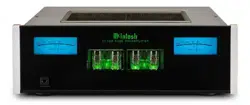
TUBE LIGHTS
The C2700 Top Cover Window allows viewing of the
six Vacuum Tubes. LEDS providing illumination may
be switched On or Off by performing the following:
1. Select “TUBE LIGHTS, On” as indicated on the
Front Panel Information Display. Refer to figures
60, 63 (on page 22) and 82.
2. Switch Off the Meter Illumination. Refer to
figure 83.
Note: Illumination of Vacuum Tubes during the “Warm
Up” period of time will continue when the Trim
Setting for TUBE LIGHTS is set to OFF.
After approximately 8 seconds the Information
Display returns to indicate the Source Selection and
Volume Level.
INFORMATION DISPLAY ILLUMINATION
The Brightness Level of C2700 Front Panel Informa-
tion Display can be adjusted from bright to dim by
performing the following:
1. Select “DISPLAY BRIGHTNESS” as indicated
on the Front Panel Information Display. Refer to
figures 60, 63 (on page 22) and 84.
2. Reduce the Brightness level by adjusting the
TRIM LEVEL. Refer to figure 85.
After approximately 8 seconds the Information
Display returns to indicate the Source Selection and
Volume Level.
PHONO ADJUSTMENTS
When the Phono MC or Phono MM Input is selected
an additional TRIM SELECT FUNCTION becomes
available for adjustment. Perform the following steps
to make the Phono Trim Adjustments:
1. Select either the Phono MM or Phono MC Source
Input.
2. Select “MC PHONO LOAD, 400Ω” or “MM
PHONO LOAD, 50pF” as indicated on the Front
Panel Information Display. Refer to figures 86 and
87.
3. Set the desired phono cartridge loading value
(Ohms for a Moving Coil Cartridge or Capaci-
tance for a Moving Magnet Cartridge) that comes
closest to the Phono Cartridge Makers recom-
mended value.
After approximately 8 seconds the Alphanumeric
Display returns to indicate the Source Selection and
Volume Level.
HXD MODE
Connect a pair of dynamic headphones to the Head-
phones Jack with a 1/4” (0.635cm) stereo phone type
plug for private listening. The default setting is for all
of the Power Amplifier Output Connections (1 and 2)
to automatically mute.
When headphones are connected to the C2700
Front Panel Jack, an additional TRIM function be-
comes available. McIntosh’s HXD brings the acousti-
cal depth and spatiality of music normally heard with
loudspeakers, to your headphones. Momentarily press
the INPUT Control, then rotate it to select “HEAD-
PHONE HXD, On”. To deactivate the HXD Mode
rotate the VOLUME Adjust Control until the Front
Panel Display indicates “HEADPHONE HXD, Off”.
Refer to figures 88 and 89.
Note: The Headphone Output is optimized for imped-
ances ranging from 100 to 600 ohms.
How to Operate the C2700, con’t
Figure 81
METER LIGHTS
Off
Figure 85
DISPLAY
BRIGHTNESS
Figure 84
DISPLAY
BRIGHTNESS
Figure 86
MC PHONO LOAD
400O
Figure 87
MM PHONO LOAD
50pF
Figure 89
HEADPHONES HXD
Off
Figure 82
TUBE LIGHTS
On
Figure 83
TUBE LIGHTS
Off
Figure 88
HEADPHONES HXD
On
26
Passthru
The C2700 will automatically turn On and switch to
the previously setup Passthru Input when the McIn-
tosh A/V Processor or Multichannel Surround Decod-
er is turned-on. The Audio Preamplifier Front Panel
Alphanumeric Display will indicate “PASSTHRU”.
Refer to figure 92.
The C2700 OUTPUT 1 and 2 Front Panel Push-but-
tons are active when in the Passthru Mode. The other
Front Panel Controls and Push-buttons are deactivated
as long as the Passthru Mode is active.
Headphones Jack
Connect a pair of dynamic headphones to the Head-
phones Jack with a 1/4” (0.635cm) stereo phone type
plug for private listening. The default setting is for all
of the Power Amplifier Output Connections (Main, 1,
and 2) to automatically mute.
When headphones are connected to the C2700
Front Panel Jack, an additional TRIM function be-
comes available. McIntosh’s HXD brings the acousti-
cal depth and spatiality of music normally heard with
loudspeakers, to your headphones. Momentarily press
the INPUT Control, then rotate it to select “HEAD-
PHONE HXD, Off”. To activate the HXD Mode
rotate the VOLUME Adjust Control until the Front
Panel Display indicates “HEADPHONE HXD, On”.
Refer to figures 88 and 89 on page 25.
Note: The Headphone Output is optimized for imped-
ances ranging from 100 to 600 ohms.
Mute
Press the MUTE Push-button, on the C2700 Front
Panel or on the Remote Control, to Mute the Audio
in all outputs (Main, Output 1, Output 2 and Head-
phones) except the FIXED OUTPUT. The Front Panel
Information Display will indicate the Source Name
and the word MUTE in place of the actual volume set-
ting. Refer to figure 90.
Pressing the Mute Push-button a second time or
adjusting the volume control (either the Front Panel or
Remote Control) will unmute the C2700.
Tone Controls
Press the Front Panel TONE Push-button to activate
the C2700 TREBLE and BASS Tone Control Cir-
cuitry for the currently selected Input Source. The
LED above the TONE Push-button will illuminate. To
bypass the TONE CONTROL CIRCUITRY for the
currently selected Input Source press the TONE Push-
button. The LED above the TONE Push-button will
extinguish.
Refer to figure 60, on page 22 . The C2700 remem-
bers for each selected Input whether the Tone Control
Circuitry is active or bypassed.
Note. The audio signal present at the FIXED OUT
Jacks is unaffected by the TONE Circuitry.
Output 1 and 2
Press the Front Panel OUTPUT 1 or OUTPUT 2
Push-button or use the Remote Control and press the
SETUP/BLUE Push-button followed by the OUTPUT
1 or OUTPUT 2 Push-button, to send audio to sepa-
How to Operate the C2700, con’t
rate Power Amplifiers connected to the rear panel
OUTPUT 1 or 2 Jacks. It also activates the POWER
CONTROL TRIGger 1 or 2 Jacks on the rear panel
of the C2700. To stop the Audio and Power Control
Signals from going to the separate Power Amplifiers,
press the same Push-button(s) a second time.
Trim
Momentarily press the Front Panel INPUT Control to
activate the C2700 Trim Functions. Rotate the INPUT
Control to select the desired Trim Function and then
use the VOLUME (adjust) Control to change the Trim
setting. Refer to figure 60 on page 22. The Remote
Control TRIM and LEVEL UP / DOWN Push-buttons
may also be used. Approximately 8 seconds after Trim
Function Selection and/or adjustments have stopped,
the C2700 will switch the Trim Mode Off.
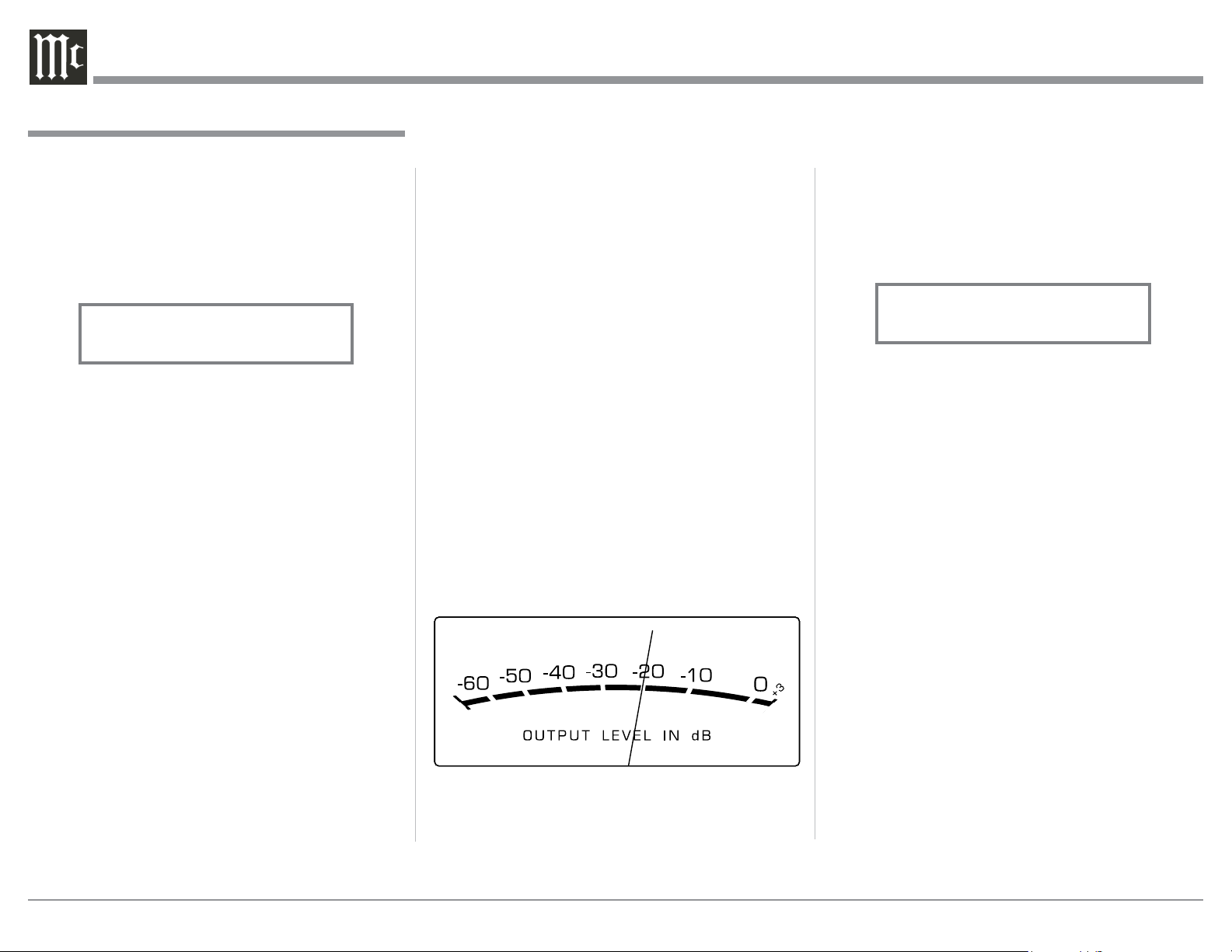
Output Meters
The C2700 Output Meters indicate the Output Level
in Decibels (dB) available at the MAIN, OUTPUT 1
and 2 Connectors/Jacks to drive Power Amplifiers.
Refer to figure 91.
The Meters are calibrated in dB (decibels) and respond
to all the peaks contained in the musical information.
A meter reading of 0dB indicates the C2700 is deliver-
ing its rated output.
Figure 90
INPUT: BAL 1
MUTE
Figure 91
Figure 92
PASSTHRU
27
Purpose: To Install the McIntosh
USB Audio Windows Driver for use with
McIntosh Products with an USB-Digital
Audio Input.
Requirements: 1. A PC Computer with a functioning
USB Port.
2. Windows 7 (SP1 or greater),
Windows 8 (8.1) or Windows 10
Operating System.
3. An USB Cable with Type A to
Type B Connectors.
Installing the Software
It is important to first install the downloaded software
on your computer before connecting the McIntosh
Product to the computer. The USB Driver is included
in the downloaded software package.
Note: Before installing this software, please check to see
if the McIntosh Product(s) with the USB-Digital
Audio Input has the latest firmware version, if not
update the firmware first.
1. Unzip the downloaded McIntosh Windows USB
Driver Software Package.
The C2700 USB Input is compatible with PC Com-
puters using Microsoft
®
, Windows 7 (SP1), Windows
8.1 and Windows 10. It is also compatible with Apple
®
Macintosh
®
Computers using OS-10.6.8 or later.
When using a PC Computer with Windows, a spe-
cial McIntosh USB Audio Software Driver needs to be
installed on the PC Computer. The driver needs to be
installed before connecting the C2700 USB Input to
the USB Port on the computer.
Note: If an Apple Macintosh computer is used with the
C2700, no additional driver is required.
The McIntosh USB Audio Windows Driver is
available for download from the McIntosh Web Site:
http://www.mcintoshlabs.com/support/product-
support
Refer to figure 95.
Under “PRODUCT CATEGORY” select “Pre-
amplifiers” then under “MODEL NUMBER” select.
Click on “SEARCH” then select McIntosh-HD USB
Audio Windows Drive D v1.0 and download the PC
Windows Driver. Follow the instructions below to
install the McIntosh C2700 Driver:
Refer to figure 96.
How To Make a Recording
1. Select the desired signal source you wish to record
by using the Front Panel INPUT Control or us-
ing the INPUT UP / DOWN Push-button on the
Remote Control.
2. Adjust the record level using the recorder level con-
trol and proceed with the recording process.
3. Listen to the playback of the program source just
recorded by selecting the Input Source connected to
the recorder component output.
Optical and Coaxial Digital Inputs
When a Digital Input (Optical or Coaxial Connection)
on the C2700 is selected, the Front Panel Informa-
tion Display indicates the sampling frequency when a
signal is present. Refer to figure 93.
During the time there is no Digital Signal present the
display will indicate “______”. Refer to figure 94.
USB Input Operation and Driver Installation
The C2700 USB Input provides the capability to play-
back music from a computer, when the computer is
connected to the rear panel USB connector.
Note: The USB Input is for direct connection to a com-
puter only. To playback music from an USB Drive,
connect the USB Drive to another USB Port on
the computer and select the USB Drive with the
Media Playback Program.
How to Operate the C2700, con’t
Figure 93
COAX 1
15%
48kHz
Figure 94
COAX 1
15%
______
Figure 95
Figure 96

28
Control Panel Settings
To activate the McIntosh-HD USB Audio Control
Panel, click on the “McIntosh Icon” (located in the
Windows notification area on the right side of the Task
Bar) or click on the Windows “Show hidden icons”,
then select the “McIntosh Icon”. Refer to figures 101 -
104.
2. Install the unziped McIntosh Windows USB
Driver Software.
USB Connection
Connect the USB Cable with Type A to Type B con-
nectors between the PC
Computer and the Mc-
Intosh Product with the
USB-Digital Audio Input.
An Icon will appear On-
Screen indicating Win-
dows has found new hardware. Refer to figures 97 and
98.
Windows Sound Settings
For proper operation of the McIntosh Product via the
Computer USB Connection, it
is required to make changes to
Windows Sound Settings:
1. From the Windows
START button, click on
“CONTROL PANEL”
followed by selecting
“SOUND”. Refer to
figure 99.
2. Referring to figure 100,
first select “McIntosh-
HD HS.
Figure 97
Figure 98
Figure 99
Figure 100
Figure 101
Figure 102
Notes: 1. It is not necessary for the McIntosh-HD USB
Audio Control Panel to be running, unless it is
desired to make changes to the default settings.
2. The McIntosh-HD USB Audio Control Panel
displays the current Sampling Rate, Bit-Rate
and Buffer Size for the music streaming from the
computer into the C2700.
3. When the Media Stream Program on the com-
puter is set to output in the “ASIO” format, the
McIntosh -HD USB Audio Control Panel allows
for changing the settings parameters on the fly.
USB Music Playback
When the USB Input is selected on the McIntosh
C2700, the Front Panel Display indicates the Sampling
Rate (refer to figures 105 and 106 for PCM Signals).
Figures 107 and 108 indicate a Sampling Rate of 128
or 256 times the Sampling Rate of a CD Disc for the
incoming DSD Digital Audio Signal.
Figure 103
Figure 104
Figure 105
USB
46%
44.1kHz
Figure 106
USB
51%
352.8kHz
29
The Sampling Rate and the Bit Rate are determined
by the original recording, the Application Output
Format (when available) and the McIntosh-HD Control
Panel Settings.
Note: In general, when the original music is recorded
at a higher Sampling Rate, the result is usually
more detail in the music. However, this higher
rate results in consuming larger amounts of stor-
age space. The Sample Rate usually should be set
to match the Sample Rate of the music recording
being played back.
There are many third party Applications (besides
Applications like Windows Media Player) for stream-
ing music from the computer to McIntosh C2700 USB
Input. An example of just one of the available applica-
tions is “JRiver Media Center”.
Reset of Microprocessors
In the unlikely event the controls of the C2700 stop
functioning, the microprocessors can be reset by per-
forming the following:
1. Press and hold in the STANDBY/ON Push-button
until the LED above the STANDBY/ON Push-
button illumination is extinguished. Then release
the STANDBY/ON Push-button.
2. To switch the C2700 back On, press the STAND-
BY/ON Push-button.
Note: This can be performed with the C2700 On or in
the Standby Mode.
How to Operate the C2700, con’t
Figure 107
USB
46%
DSD128
Figure 108
USB
51%
DSD256
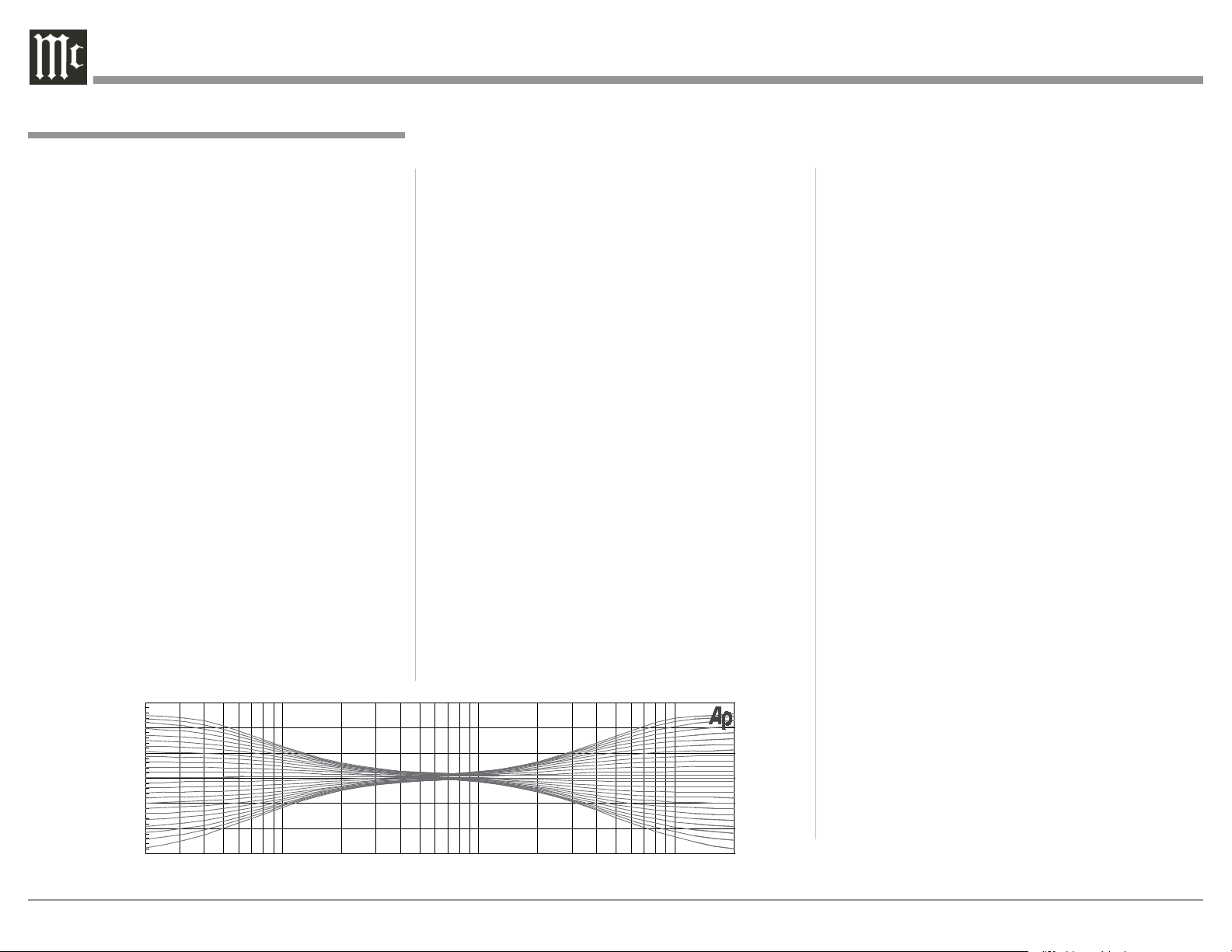
30
Specifications
Specifications
Frequency Response
+0, -0.5dB from 20Hz to 20,000Hz
+0, -3dB from 15Hz to 100,000Hz
Total Harmonic Distortion
0.08% from 20Hz to 20,000Hz
Rated Output
2.5V Unbalanced, 5V Balanced (Main)
450mV (Fixed Output)
Maximum Voltage Output
8V RMS Unbalanced, 16V RMS Balanced
Sensitivity (for rated output)
High Level, 450mV Unbalanced, 900mV Balanced
Phono MM, 4.5mV
Phono MC, 0.45mV
Signal To Noise Ratio (A-Weighted)
High Level - 100dB (Below rated output)
MM Phono - 82dB (Below 5mV input)
MC Phono - 80dB (Below 0.5mV input)
Input Impedance
High Level - 22K ohms Unbalanced
44k ohms Balanced
Phono MM - 50 to 800pF, in 50pF steps; 47K ohms
Phono MC - 25, 50, 100, 200, 400 or 1,000 ohms;
100pF
Maximum Input Signal
High Level, 5V Unbalanced, 10V Balanced
Phono MM, 80mV
Phono MC, 8mV
Voltage Gain
High Level to Fixed Output: 0dB
High Level to Main Output: 15dB
Phono MM to Record Output: 40dB
Phono MC to Record Output: 60dB
Output Impedance
100 ohms Unbalanced
200 ohms Balanced
Headphone Load Impedance
100 ohms to 600 ohms
Digital Input Sample Rates
Optical: PCM - 16Bit, 24Bit - 44.1kHz to 192kHz
Coaxial: PCM -16Bit, 24Bit - 44.1kHz to 192kHz
MCT: PCM, SACD, -16Bit, 24Bit - 44.1kHz to 192kHz
USB: PCM - 16Bit, 24Bit, 32Bit - 44.1kHz to 384kHz
DXD - DXD352.8kHz, DXD384kHz
DSD - DSD64, DSD128, DSD256, DSD512
HDMI: PCM 24bit, 44.1kHz - 192kHz
DTS
Dolby Digital
Power Control and Trigger Output
12VDC, 25mA
Tube Complement
6 Tubes, Five - 12AX7A and One - 12AT7
(viewed thru the Top Cover Window)
Power Requirements
Field AC Voltage conversion of the C2700 is not pos-
sible. The C2700 is factory configured for one of the
following AC Voltages:
100 Volts, 50/60Hz at 50 watts
110 Volts, 50/60Hz at 50 watts
120 Volts, 50/60Hz at 50 watts
127 Volts, 50/60Hz at 50 watts
220 Volts, 50/60Hz at 50 watts
230 Volts, 50/60Hz at 50 watts
240 Volts, 50/60Hz at 50 watts
Standby Power, less than 0.5 watts
Note: Refer to the rear panel of the C2700 for the correct
voltage.
Overall Dimensions
Width is 17-1/2 inches (44.45cm)
Height is 7-5/8 inches (19.37cm) including feet
Depth is 18 inches (45.72cm) including the Front
Panel, Knobs and Cables
Weight
29.5 pounds (13.4 kg) net, 45 pounds (20.4 kg) in ship-
ping carton
Shipping Carton Dimensions
Width is 27 inches (68.6cm)
Height is 14 inches (35.6cm)
Depth is 25 inches (63.5cm)
20 20k50 100 200 500 1k 2k 5k 10k
0
+6
-6
+12
-12
dB
Hz
Tone Controls
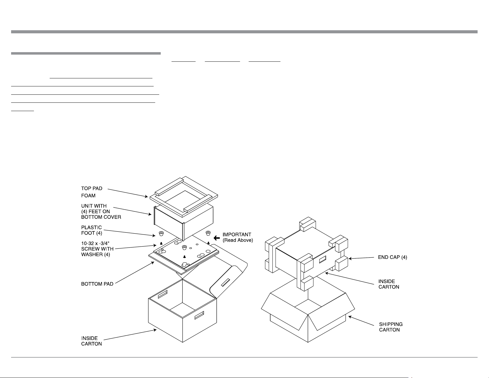
31
Packing Instructions
Packing Instructions
In the event it is necessary to repack the equipment for
shipment, the equipment must be packed exactly as
shown below. It is very important that the four plas-
tic feet are attached to the bottom of the equipment.
This will ensure the proper equipment location on the
bottom pad. Failure to do this will result in shipping
damage.
Use the original shipping carton and interior parts
only if they are all in good serviceable condition. If
a shipping carton or any of the interior part(s) are
needed, please call or write Customer Service Depart-
ment of McIntosh Laboratory. Refer to page 2. Please
see the Part List for the correct part numbers.
Quantity Part Number Description
1 033888 Shipping carton only
4 033887 End cap
1 033697 Inside carton only
1 034414 Top pad (foam)
1 034576 Bottom pad
4 017937 Plastic foot
4 400159 #10-32 x 3/4” screw
4 404080 #10-7/16” Flat washer
( )

The continuous improvement of its products is the
policy of McIntosh Laboratory Incorporated who
reserve the right to improve design without notice.
Printed in the U.S.A.
McIntosh Laboratory, Inc.
2 Chambers Street
Binghamton, NY 13903
www.mcintoshlabs.com
McIntosh Part No. 24101900