User Manual
AIR CONDITIONER FEATURES
This unit has many features. The servicer must be familiar with these features in order to properly service the unit.
Compressor Restart Delay
This feature extends the overall life of the compressor by preventing the shorting cycling of the air conditioner. When the compressor restarts, the unit is designed to give a minimum of three minutes to have a time of equalizing the refrigerant pressures for optimizing cycling.
Memory
The unit has memory. If power is lost, all of the control settings (mode, fan speed, on/off and configuration) are remembered. So when power is restored, the unit will start back up in the mode (and configuration) it was in, before power was lost.
Automatic Evaporator Freeze Protection
Automatically keeps the evaporator from freezing, the compressor is turned off and the indoor fan is turned on when the evaporator temperature is too low. If the evaporator temperature is not too low this function is off.
Automatic Quick Warm-up (for heat pump models only)
If the room temperature falls to 4.5°C/8°F below the set point temperature, the reverse cycle heat is shut off and the electric strip heat is turned on for one cycle, until the set temperature is satisfied.
LED Indicators and Buttons
The touch pad has buttons for MODE,FAN, POWER, SETPOINT UP and SETPOINT DOWN. It also has LEDs that correspond to the mode, fan speed, power, and set point operation to indicate the unit status. LEDs for HIGH, MED and LOW indicate the fan speed that is selected. LEDs for FAN, COOL and HEAT indicate what operating mode is active. LED for POWER is the unit ON/OFF status LED. If the unit is in ON mode, the LED will be green. If the unit is OFF, the LED will be off.
High Temperature Protection In Heating Operation
The compressor and (or) electric heater will be switched off to prevent damage in high indoor blow air temperature or error indoor temperature sensor.
Temperature Display Configuration(°F or °C)
The unit can display in either °F or °C.
CONTROL PANEL OPERATION
The control panel keypad will look like the following Fig. 1. For some models with REMOTE SIGNAL RECEPTOR, the unit can be controlled by the control panel alone or by the remote.
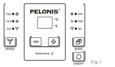
POWER
Press the POWER button to turn the unit on or off. When the unit is on, the power indicator light will be green. When the unit is off, the light will go out.
MODE
Push this button to cycle through the modes from COOL-HEAT-FAN-COOL.The indicator light beside the “MODE” option will illuminate, identifying the mode selected.
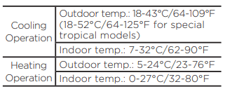
- COOL: The range of set temperature is 62°F-86°F (17°C-30°C). Cooling begins automatically when the room temperature is above the set point,and stops when the room temperature is 4°F (2°C) below the set point. But the compressor will run 5 minutes at least in COOL mode before stopping. The fan runs in continuous mode.
- HEAT: The range of set temperature is 62°F-84°F (17°C-29°C). For heat pump models, the unit can alternate to run between the reverse cycle heat mode and electric mode according to the difference between the setting temperature and the room temperature. The fan motor cycles on and off with the compressor and electric heater.
- FAN: Fan operation only without heating and cooling.
NOTES
The reverse cycle and electric heater cannot be ran at the same time. In following cases, it is normal that the reverse cycle does not operate.
- When the outdoor temperatrue is lower than 4°C/40°F or the room temperature falls to 4.5°C/8°F below the set point temperature.
- There is a 3-minute minimum compressor run time at any setting to prevent short cycling.The indoor fan motors starts before the compressor and stops after the compressor cycles off.
- Push the S1 on the DIP SWITCHES to UP (ON) position.
- When frost builds up to the evaporator coils, the unit will defrost automatically and the compressor will cycle off.
UP/DOWN BUTTONS ( + / - )
Push the UP (or DOWN) button to increase (or decrease) the set temperature of the unit in cooling or heating mode. The temperature can be set by increments of 1° F (1°C). The setting temperature appears in the display.
FAN (FAN SPEED)
Every time you push this button, the fan speed cycles through the settings as follows: HIGH-MED-LOW-HIGH.
DISPLAYS:
Shows the set temperature in °C or °F.While on Fan only mode, it shows the room temperature.
Control code (on some models):
LC - Control panel operation not available.The unit can be controlled by using Wired Wall Thermostat only.
FC - Pads on the control panel and wire controller are not available. The unit can be setted by using FRONT DESK CONTROL only.
Error codes:
AS - Room temperature sensor error
ES - Evaporator temperature sensor error
CS - Condenser temperature sensor error
OS - Outside temperature sensor error
HS - Exhaust temperature sensor error
LE - Wire controller error
Other codes:
LO - Room temperature is lower than 0°C/32°F;
HI - Room temperature is higher than 37°C/99°F;
FP - Low temperature protection.
DIP SWITCHES CONFIGURATIONS
REMOVING THE FRONT PANEL
- Dip switches controls are located behind front panel, through an opening below the control panel. To access, remove front panel. See Fig. 2.
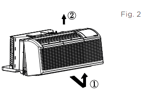
- Pull out at the bottom to release it from the tabs 1.
- Then lift up 2
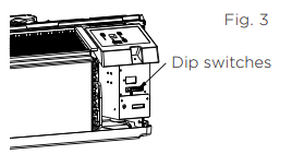
- Dip switches are accessible without opening the control box. See Fig. 3.
- Unit must be powered OFF to effectively change their status
DIP SWITCHES CONFIGURATIONS
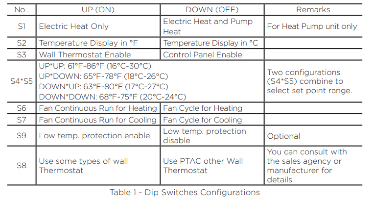
See Table 1 and Fig. 4 for Dip Switches configurations and functions of each dip switch position.
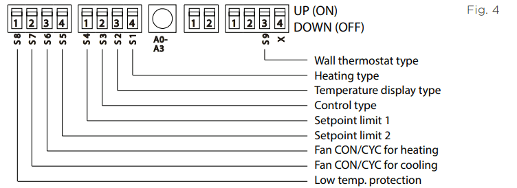
Wall Thermostat Enable
A wired wall thermostat can be connected to the unit. If it is, this dip switch must be moved to the Wall Thermostat Enable Position, before the wall thermostat will begin control.
Low temperature protecton (optional)
If unit senses a room temperature below 32°F (0°C), the fan motor and electric strip heat will turn on and warm the room to 40°F (4.4°C). The fan stops a short time after the temperature is satisfied.
Electric Heat Only (for heat pump unit only)
This setting is typically used for Emergency Heating.
Setpoint Temperature Limits
Provides a restricted range of temperature control.
Heat and Cool Fan CON/CYC Dip-switches
Allows the fan to operate in continuous or cycle modes while the unit is in heating and cooling mode.
Allows fan to run continuously, circulating air even when the temperature setting has been satisfied. This switch helps to maintain the room temperature closer to the thermostat setting.
This setting allows the fan to cycle on and off with the compressor or electric heater. The fan stops a short time after the temperature setting is satisfied.
DIP SWITCHES CONFIGURATIONS by PANEL CONTROL
- Turn off the unit.
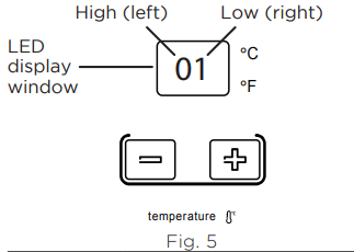
- Press the up (+) and down (-) buttons together for 3 seconds to activate the dip switches configurations by panel control (see Fig. 5).
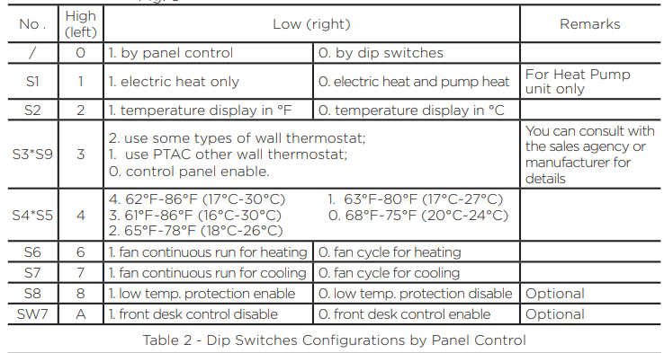
- See Table 2 for Dip Switches configurations and functions by panel control.
- Display function settings with 2 digitals in LED display window, high (left) for dip switches, low (right) for functions (see Fig. 5).
- Press up (+) button to set the dip swithces, press down (-) button to set the functons.
NOTE
1. The LED display window will show 00 when you first enter the setting mode, only when you set 01, can you start the next settings.
2. To activate front desk control function, you need to pull the dip switch SW7 to DOWN (OFF), and then set the panel control to “A0”.
3. After all switches have been set, press up (+) and down (-) buttons together for 3 seconds to exit the operation interface and cut off the power. When re-power on, the settings are activated.
WALL THERMOSTAT TERMINAL (Optional)
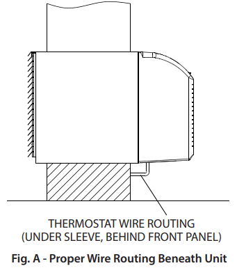
Thermostat Wire Routing
Thermostat wire is field supplied. Recommended wire gauge is 18 to 20 gauge solid thermostat wire.
NOTE It is recommended that extra wires are run to unit in case any are damaged during installation. Thermostat wire should always be routed around or under, NEVER through, the wall sleeve. The wire should then be routed behind the front panel to the easily accessible terminal connector
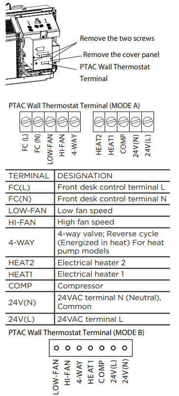
Wired Wall Thermostat Connection Instructions
Remove the two screws as shown below and take the cover panel down to enable wall thermostat
NOTES
- Use terminal 4-way for heat pump connection only.
- Suggest to set the compressor protection time more than 3 minutes in the wall thermostat. If set less than 3 minutes, the compressor will still delay start by 3 minutes.
- Wall thermostat must have a 4-way valve output.
- For thermostats that have only one fan speed output (on or auto), the fan speed is determined by how the terminal connector is wired. If Low fan is desired, wire the G output from the thermostat to (LOW-FAN) on the units terminal block. If High fan is desired, wire the G output from the thermostat to (HI-FAN) on the units terminal block.
- The range of set temperature of the wall thermostat must be in the allowable range of the DIP switch setting.
- The wall thermostat must also have the correct unit type setting: heat pump or no heat pump.
- If the wall thermostat has only one electrical heater output, connect the two terminals of HEAT 1 and HEAT 2 together to form one terminal and then connect. Otherwise, connect both HEAT 1 and HEAT 2 terminals to the wall thermostat heater outputs.
- Please do not remove the control panel.
FRONT DESK CONTROL
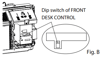
The controller can handle a switch signal from FC (L) and FC (N) input, called front desk control. Input must be 24VAC. If system doesn’t receive a 24VAC signal, it will turn the unit off; otherwise, the unit runs in normal control.
- The DIP switch can control the FRONT DESK CONTROL feature. The DIP switch is on the DOWN position, the unit will be turn off; otherwise, the unit runs in normal control. See Fig B.
INSTALLATION INSTRUCTIONS
HOW TO INSTALL THE UNIT
- For existing sleeve, you should measure the wall sleeve dimensions.
- Install the new air conditioner according to these installation instructions to achieve the best performance. All wall sleeves used to mount the new air conditioner must be in good structural condition and have a rear grille that securely attaches to the sleeve or the flange of the sleeve to secure the new air conditioner.
- To avoid vibration and excess noise, make sure the unit is installed securely and firmly.
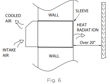
- When installing the sleeve, make certain there is nothing within 20” of the back of the unit that would interfere with heat radiation and exhaust air flow (see Fig. 6).
PREPARATION OF SLEEVE ASSEMBLY (optional)
Refer to the installation instruction of sleeve assembly for details.
PREPARATION OF REAR GRILLE ASSEMBLY (optional)
Refer to the installation instruction of rear grille assembly for details.
UNIT INSTALLATION
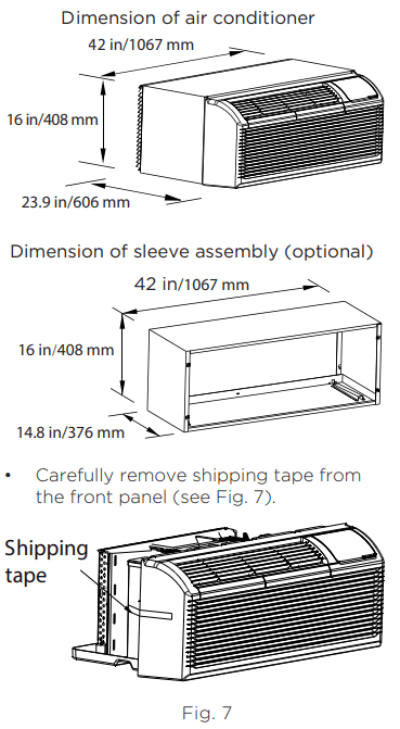
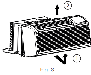
- Remove the front panel. (see Fig. 8)
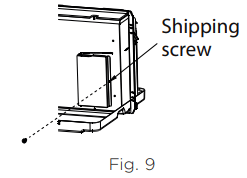
- Remove the shipping screw from the vent door - only if ventilation is desired.(see Fig. 9)
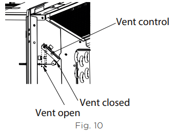
- Rotate the vent control lever to either open or close the vent door. (see Fig. 10)
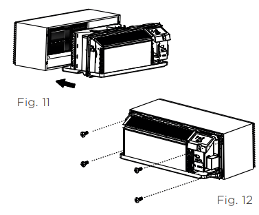
- Lift unit level and slide unit into wall sleeve until firmly against front of wall sleeve and secure with 4 screws and washers (supplied in the SLEEVE ASSEMBLY) through the unit flange holes. (see Fig. 11 and Fig. 12).
- Reinstall front panel. (see Fig. 13)
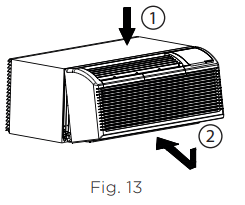
- Place tabs over top rail 1. Push Inward at bottom until panel snaps into place 2.
CARE AND CLEANING
FRONT PANEL AND CASE
Turn unit off and disconnect power supply.
To clean, use water and a mild detergent. DO NOT use bleach or abrasives. Some commercial cleaners may damage the plastic parts.
OUTDOOR COIL
Coil on outdoor side of unit should be checked regularly. Unit will need to be removed to inspect dirt build-up that will occur on the inside of the coil.If clogged with dirt and soot, coil should be professionally cleaned of debris. Clean inside and outside of outdoor coils regularly.
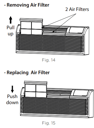
AIR FILTERS
The most important thing you can do to maintain unit efficiency is to clean the filters once every two weeks as required. Clogged filters reduce cooling, heating and airflow.
Keeping filters clean will:
- Decrease cost of operation.
- Save energy.
- Prevent clogged indoor coil.
- Reduce risk of premature component failure.
To Clean Air Filters:
- Vacuum off heavy soil.
- Run water through filter.
- Dry thoroughly before replacing.
VENT DOOR FILTER
- If the vent door is open, access requires the removal of the unit from the wall sleeve. Clean the vent filter twice a year or as required.
- Make sure to remove the shipping screw from the vent door. (see Fig. 9)
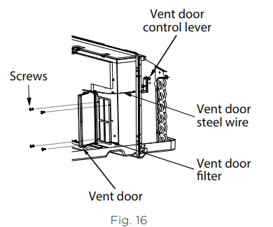
- Rotate the vent control lever to open the vent door. (see Fig. 16)
- Remove four screws from the vent door filter. (see Fig. 16)
- First pull out the vent door steel wire from the hole of the vent door, then take off the vent door and filter. (seeFig. 16)
- Clean the filter. Dry thoroughly before replacing.
- Replace the vent door and filter, reinstall the four screws.
- Reinsert the vent door steel wire into the hole of the vent door.
TROUBLESHOOTING TIPS
| POSSIBLE CAUSES |
SOLUTIONS |
|
UNIT DOES NOT START
- Unit may have become unplugged.
- Fuse may have blown.
- Circuit breaker may have been tripped.
- Unit may be off.
- Unit may be in a protection mode.
|
- Check that the plug is plugged securely in wall receptacle. If not, plug in securely.
Note: Plug has a test/reset button on it. Make sure that the plug has not tripped.
- Replace the fuse. See Note 1.
- Reset circuit breaker. See Note 1.
- Turn unit on (bottom right button on keypad).
|
|
UNIT NOT COOLING/HEATING ROOM
- Unit air discharge section is blocked.
- Temperature setting is not high or low enough.
Note: Setpoint limits may not allow the unit to heat or cool the room to the temperature desired. Check section on dipswitch settings.
- Unit air filters are dirty.
- Room is excessively hot or cold when unit is started.
- Vent door left open.
- Unit may be in a protection mode.
- Compressor is in time delay
|
- Make sure that curtains, blinds, or furniture are not restricting or blocking airflow. If so, move those items to allow for proper airflow.
- Reset to a lower or higher temperature setting.
- Remove and clean filters.
- Allow sufficient amount of time for the unit to heat or cool the room. Also please note that other heat sources, such as cooking and increased occupancy, can also affect the time required to heat or cool the room.
- Close vent door.
- Check dipswitch and wall thermostat settings for desired comfort.
- Wait approximately 3 minutes for compressor to start.
|
| DISPLAY HAS STRANGE NUMBERS / CHARACTERS ON IT |
- The unit may be in a protection mode.
- The unit may be set for °C (instead of °F).
|
| UNIT MAKING NOISES |
Clicking, gurging and whooshing noises are normal during operation of unit. |
| WATER DRIPPING OUTSIDE |
If a drain kit has not been installed, condensation runoff during very hot and humid weather is normal. See Note 2. If a drain kit has been installed and is connected to a drain system, check gaskets and fittings around drain for leaks and plugs. |
|
WATER DRIPPING INSIDE
- Wall sleeve is not installed level.
|
Wall sleeve must be installed level for proper drainage of condensation. Check that installation is level and make any necessary adjustments. |
|
ICE OR FROST FORMS ON INDOOR COIL
- Low outdoor temperature.
- Dirty filters.
|
- When outdoor temperature is approximately 55°F or below, frost may form on the indoor coil when unit is in Cooling mode. Switch unit to FAN operation until ice or frost melts.
- Remove and clean filters.
|
|
COMPRESSOR PROTECTION
Power may have cycled, so compressor is in a restart protection.
|
- Random Compressor restart - Whenever the unit is plugged in, or power has been restarted, a random compressor restart will occur. After a power outage, the compressor will restart after approximately 3 minutes.
- Compressor Protection - To prevent short cycling of the compressor, there is a random startup delay of 3 minutes.
|
| ELECTRIC HEATING FAILURE |
Clean the evaporator twice yearly by qualified personnel |
NOTES
1. If circuit breaker is tripped or fuse is blown more than once, contact a qualified electrician.
2. If unit is installed where condensation drainage could drip in an undesirable location, an accessory drain kit should be installed and connected to drain system.