Loading ...
Loading ...
INSTALLATION INSTRUCTIONS
KNOCK-OUT
(TWIST TO
REMOVE)
KNOCK-OUT
(TWIST TO
REMOVE)
STRAIN RELIEF
CONNECTOR
SUPPLY
WIRE
Agujero ciego
(gire para
quitarlo)
Conector de
atenuacion de
tension
Cable de
suministro
PLACEMENT: For best results install the NLW heater on an inside wall. Headers and bracing are not necessary.
NOTE: The wall can must be installed in the TOP UP (vertical) position only. Heater is not approved for ceiling mount.
THERMOSTAT: A built-in double pole thermostat is included.
REQUIRED MINIMUM distance of 6 inches from adjacent surfac-
es and 6 inches from the oor (See Figure 4). However, Cadet
RECOMMENDS 12 inches from adjacent surfaces and oor for
longer and cleaner performance. Heaters must be spaced at least
3 feet apart.
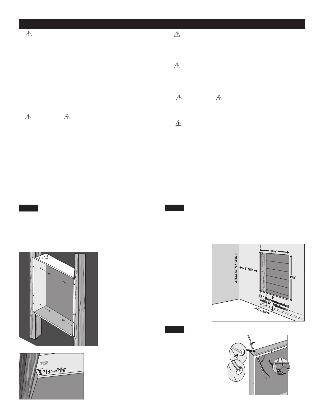
Secure the wall can to the studs with screws through the larger
(3/16 inch) holes. (See Figures 1 and 2).
Cut a hole 14 1/4 inches wide by 19 1/4 inches high next to a wall
stud. REQUIRED MINIMUM distance of 6 inches from adjacent
surfaces and 6 inches from the oor (See Figure 4). However, Ca-
det RECOMMENDS 12 inches from adjacent surfaces and oor
for longer and cleaner performance. Heaters must be spaced at
least 3 feet apart.
Figure 3
Figure 4
Figure 2
Figure 1
Face of wall can must extend
1/2 inch or 5/8 inch from face
of stud to allow for thickness of
sheetrock. Mount wall can ush
with nished surface.
STEP 2
Route Supply Wires
Route supply wire
from circuit breaker to
top of wall can. Re-
move knockout and
attach the supply wire
with a strain relief
connector, leaving 6
inches of wire lead
for later use. Connect
supply ground wire to
grounding screw in
wall can (See Figure
3).
1. WARNING
Verify that the electrical supply wires are the same
voltage as the heater.
2. If replacing an existing heater, check the label
of the old heater.
3. All electrical work and materials must comply
with the National Electric Code (NEC), the Occu-
pational Safety and Health Act (OSHA), and all
state and local codes.
4. If you need to install a new circuit or need addi-
tional wiring information, consult a qualied elec-
trician.
5. Use copper conductors only.
6. WARNING
Risk of Electrical Shock. DO NOT install the heat-
er directly above bathtub or sink. DO NOT install
in shower stall area (Manufacturer recommends a
minimum 2 foot clearance).
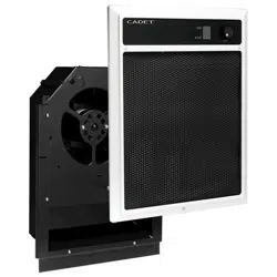
7. Heater must be installed in a wall can:
Model NLW Wall Can NLWC or NLWCS
8. WARNING
Risk of Fire. DO NOT install the heater in a oor,
in the ceiling, below a towel bar, behind a door,
or anywhere the air discharge may be blocked in
any manner.
9. WARNING
Fire or Explosion May Occur. A heater has hot
and arcing or sparking parts inside. Do not use it
in areas where gasoline, paint, or ammable va-
pors or liquids are used or stored.
10. WARNING
Risk of Electrical Shock. Connect grounding lead
to grounding screw provided. Keep all foreign ob-
jects out of heater.
11. WARNING
Risk of Fire. This heater is hot when in use.
Caution—High Temperature. Risk of Fire. Keep
electrical cords, drapery, furnishings, and other
combustibles at least 3 feet from the front of the
heater and 6 inches above and on both sides.
__________________________
Part One
__________________________
How do I install for new construction?
STEP 1
Mount The Wall Can
How do I install in an existing wall?
STEP 1
Cut A Hole In The Wall
SUPPLY
GROUNDING
WIRE
TOP
VIEW
GROUNDING
SCREW
VISTA
PRIMERA
TORNILLO
DE PUESTA
A TIERRA
CABLE DE PUESTA
A TIERRA DEL
SUMINISTRO
Page 3
Loading ...
Loading ...
Loading ...