

Contents
31MJK630 Goldwing (GL1800)
MOM 15482 (1506)
Contents
These pages give an overview of the contents of your owner’s manual. The first
page of each section lists the topics covered in that section.
Motorcycle Safety............................................................................................
1
Important safety information you should know, plus a look at the safety-
related labels on your motorcycle.
Instruments & Controls................................................................................
11
The location and function of gauges, indicators, controls, and the Multi
Information Display on your motorcycle and operating instructions for
various controls and features.
Before Riding.................................................................................................
43
The importance of wearing a helmet and other protective gear, how to make
sure you and your motorcycle are ready to ride, and important information
about loading.
Basic Operation & Riding............................................................................
69
How to start and stop the engine, shift gears, and brake. Also, riding
precautions and important information about riding with a passenger or cargo.
Audio Systems................................................................................................ 95
The location, function, and operation of the audio components on your
motorcycle.
Servicing Your Honda.................................................................................
149
Why your motorcycle needs regular maintenance, what you need to know
before servicing your Honda, an owner maintenance schedule, and
instructions for specific maintenance and adjustment items.

Contents
Contents
Tips....................................................................................................................... 219
How to store and transport your motorcycle and how to be an
environmentally responsible rider.
Taking Care of the Unexpected
....................................................................... 225
What to do if you have a flat tire, your engine won’t start, etc.
Technical Information
....................................................................................... 251
ID numbers, technical specifications, and other technical facts.
Consumer Information
..................................................................................... 269
Information on warranties, emission controls, how to get Honda service
manuals, and
...
‘‘Reporting Safety Defects’’....................................................................... 276
Index..................................................................................................................... 278
Quick Reference
Handy facts about fuel, engine oil, tire sizes, and air pressures.
2016
Honda GL1800
GOLDWING
OWNER’S MANUAL

Introduction
Introduction
Congratulations on choosing a GL1800 GOLDWING motorcycle.
When you own a Honda, you’re part of a worldwide family of satisfied
customers – people who appreciate Honda’s reputation for building quality into
every product.
Your GOLDWING has earned its reputation as the ultimate luxury touring
motorcycle. It comes loaded with power, unequaled cargo space, a sophisticated
audio system, adjustable windscreen, suspension, a Tire Pressure Monitoring
System (TPMS), ventilation, and other unique features to provide maximum
convenience and comfort. Additionally, there are special packages available:
Anti-Lock Brake System (ABS), Navigation System with optional XM
®
Radio
and Airbag.
Before riding, take time to get acquainted with your motorcycle and how it
works. To protect your investment, we urge you to take responsibility for
keeping your motorcycle well maintained. Scheduled service is a must, of
course. But it’s just as important to observe the break-in guidelines, and perform
all pre-ride and other periodic checks detailed in this manual.
We also recommend that you read this owner’s manual before you ride. It’s full
of facts, instructions, safety information, and helpful tips. To make it easy to
use, the manual contains a detailed list of topics at the beginning of each section
and an index at the back of the book.
As you read this manual, you will find information that is preceded by a
symbol. This information is intended to help you avoid damage to your
Honda, other property, or the environment.

Introduction
Introduction
Read the Warranties Booklet (page 271) thoroughly so you understand the
coverages that protect your new Honda and are aware of your rights and
responsibilities.
If you have any questions, or if you ever need special service or repairs,
remember that your dealer knows your motorcycle best and is dedicated to your
complete satisfaction.
Please report any change of address or ownership to your dealer so we will be
able to contact you concerning important product information.
You may also want to visit our website at
USA: www.powersports.honda.com.
Canada: www.honda.ca.
Happy riding!
California Proposition 65 Warning
WARNING: This product contains or emits chemicals known to the State of
California to cause cancer and birth defects or other reproductive harm.
Safety Messages
A Few Words About Safety
Your safety, and the safety of others, is very important. And operating this
motorcycle safely is an important responsibility.
To help you make informed decisions about safety, we have provided operating
procedures and other information on labels and in this manual. This information
alerts you to potential hazards that could hurt you or others.
Of course, it is not practical or possible to warn you about all hazards associated
with operating or maintaining a motorcycle. You must use your own good
judgment.
You will find important safety information in a variety of forms, including:
• Safety Labels –– on the motorcycle.
• Safety Messages –– preceded by a safety alert symbol
and one of three
signal words: DANGER, WARNING, or CAUTION.
These signal words mean:
You WILL be KILLED or SERIOUSLY
HURT if you don’t follow instructions.
You CAN be KILLED or SERIOUSLY
HURT if you don’t follow instructions.
You CAN be HURT if you don’t follow
instructions.
• Safety Headings –– such as Important Safety Reminders or Important Safety
Precautions.
• Safety Section –– such as Motorcycle Safety.
• Instructions –– how to use this motorcycle correctly and safely.
This entire manual is filled with important safety information –– please read it
carefully.

Motorcycle Safety
1
Motorcycle Safety
This section presents some of the most important information and
recommendations to help you ride your motorcycle safely. Please take a few
moments to read these pages. This section also includes information about the
location of safety labels on your motorcycle.
Important Safety Information.............................................................................
2
Accessories & Modifications ............................................................................. 4
Safety Labels...................................................................................................... 6

2
Motorcycle Safety
Important Safety Information
Your motorcycle can provide many years of service and pleasure – if you take
responsibility for your own safety and understand the challenges you can meet
while riding.
There is much that you can do to protect yourself when you ride. You’ll find
many helpful recommendations throughout this manual. The following are a
few that we consider to be most important.
Always Wear a Helmet
It’s a proven fact: helmets significantly reduce the number and severity of head
injuries. So always wear an approved motorcycle helmet and make sure your
passenger does the same. We also recommend that you wear eye protection,
sturdy boots, gloves, and other protective gear (page 44).
Take Time to Learn & Practice
Even if you have ridden other motorcycles, take time to become familiar with how
this motorcycle works and handles. Practice in a safe area until you build your skills
and get accustomed to the motorcycle’s size and weight.
Because many crashes involve inexperienced or untrained riders, we urge all
riders to take a motorcycle operator course approved by the Motorcycle Safety
Foundation (MSF). See page 46.
Ride Cautiously
Ride cautiously and keep your hands on the handlebar and feet on the footpegs.
Ride Defensively
The most frequent motorcycle collision happens when a car turns left in front of
a motorcycle. Another common situation is a car moving suddenly into your
lane.
Always pay attention to other vehicles around you, and do not assume that other
drivers see you. Be prepared to stop quickly or make an evasive maneuver. For
other riding tips, see the booklet, You and Your Motorcycle Riding Tips, which
came with your new motorcycle (USA only).

Motorcycle Safety
3
Important Safety Information
Make Yourself Easy to See
Some drivers do not see motorcycles because they are not looking for them. To
make yourself more visible, wear bright reflective clothing, position yourself so
other drivers can see you, signal before turning or changing lanes, and use your
horn when it will help others notice you.
Ride within Your Limits
Pushing limits is another major cause of motorcycle crashes. Never ride beyond
your personal
abilities or faster than conditions warrant. Remember that
alcohol, drugs, fatigue, and inattention can significantly reduce your ability to
make good judgments and ride safely.
Don’t Drink and Ride
Alcohol and riding don’t mix. Even one drink can reduce your ability to respond
to c
hanging conditions, and your reaction time gets worse with every additional
drink. So don’t drink and ride, and don’t let your friends drink and ride either.
Keep Your Honda in Safe Condition
It’s important to keep your motorcycle properly maintained and in safe riding
condition. To help avoid problems, inspect your motorcycle before every ride
and perform all recommended maintenance. Never exceed load limits (page 50),
and do not modify your motorcycle (page 5) or install accessories that would
make your motorcycle unsafe (page 4).

4
Motorcycle Safety
Accessories & Modifications
Modifying your motorcycle or using non-Honda accessories can make your
motorcycle unsafe. Before you consider making any modifications or adding an
accessory, be sure to read the following information.
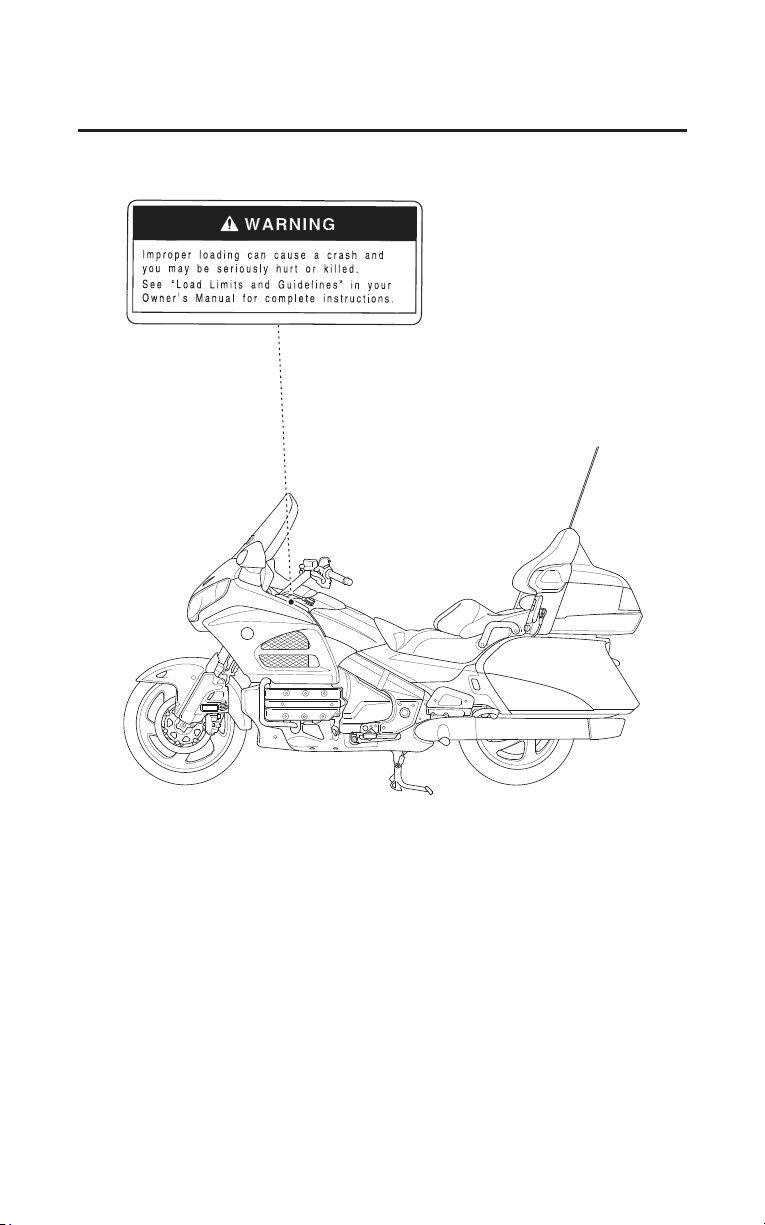
Improper accessories or
modifications can cause a crash
in which you can be seriously
hurt or killed.
Follow all instructions in this
owner’s manual regarding
accessories and modifications.
Accessories
We strongly recommend that you use only Honda Genuine Accessories that
have been specifically designed or approved and tested for your motorcycle.
Because Honda cannot test all other accessories, you must be personally
responsible for proper selection, installation, and use of non-Honda accessories.
Check with your dealer for assistance and always follow these guidelines:
• Make sure the accessory does not obscure any lights, reduce ground
clearance and lean angle, limit suspension travel or steering travel, alter your
riding position, or interfere with operating any controls.
• Do not add any electrical equipment that will exceed the motorcycle’s
electrical system capacity (page 257). A blown fuse can cause a loss of lights
or engine power (page 244).
• Do not pull a trailer or sidecar with your motorcycle. This motorcycle was
not designed for these attachments, and their use can seriously impair your
motorcycle’s handling.
• Carefully consider the weight of any accessories and any cargo stored in
those accessories to avoid exceeding the maximum weight limits.
For more information, see Load Limits, page 50.
• Modifying the tire pressure monitoring system (TPMS) or any other part of
your motorcycle’s safety systems could make the systems ineffective
(page 83).

Motorcycle Safety
5
Accessories & Modifications
Modifications
We strongly advise you not to remove any original equipment or modify your
motorcycle in any way that would change its design or operation. Such changes
could seriously impair your motorcycle’s handling, stability, and braking,
making it unsafe to ride.
Removing or modifying your lights, exhaust system, emission control system,
or other equipment can also make your motorcycle illegal.
6
Motorcycle Safety
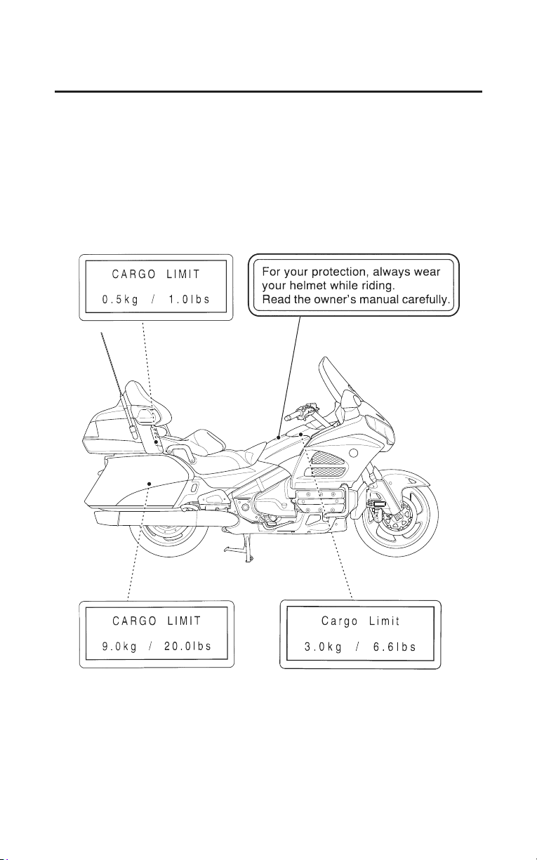
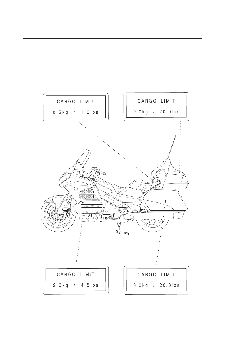
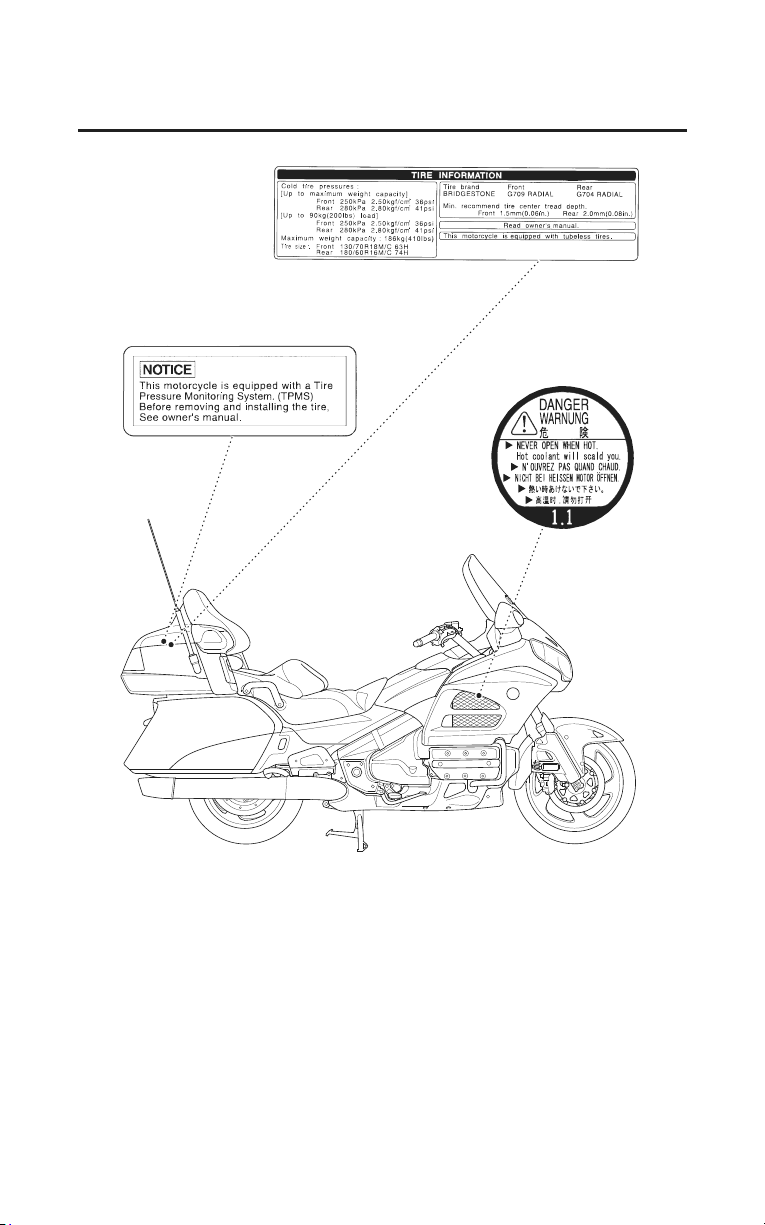
Safety Labels
Safety labels on your motorcycle either warn you of potential hazards that could
cause serious injury or they provide important safety information. Read these
labels carefully and don’t remove them.
If a label comes off or becomes hard to read, contact your dealer for a
replacement.
(Models not equipped with Airbag)
Motorcycle Safety
7
Safety Labels
8
Motorcycle Safety
Safety Labels
Motorcycle Safety
9
Safety Labels

Instruments & Controls
11
Instruments & Controls
This section shows the location of all gauges, indicators, and controls you
would normally use before or while riding your motorcycle.
The items listed on this page are described in this section. Instructions for other
components are presented in other sections of this manual where they will be
most useful.
Operation Component Locations ......................................................................12
Gauges & Indicators.......................................................................................... 15
Multi Information Display ................................................................................ 21
Opening/Ending Ceremony .......................................................................... 22
On/Off-Opening/Ending Ceremony.............................................................. 23
Special Message for Opening/Ending Ceremony ......................................... 24
Odometer/Tripmeter...................................................................................... 26
Switch the Day Mode Display and Night Mode Display ............................. 27
Display Illumination Adjustment.................................................................. 28
Digital Clock.................................................................................................30
Air Temperature Meter.................................................................................. 31
Travel Trunk & Saddlebags Open Indicator ................................................. 32
Display Type Selection ................................................................................. 33
Changing the Information Display................................................................ 34
Controls & Features ..........................................................................................35
Ignition Switch.............................................................................................. 35
Engine Stop Switch.......................................................................................36
Start/Reverse Button .....................................................................................37
Reverse (RVS) Switch ..................................................................................37
Cruise Control Switches ............................................................................... 37
Headlight Dimmer Switch ............................................................................ 38
Turn Signal Switch........................................................................................38
Horn Button ..................................................................................................38
Audio Control Switches................................................................................ 38
Hazard Switch............................................................................................... 39
Headlight Beam Adjustment Switch.............................................................40
Rear Suspension Spring Pre-load Adjustment Switch..................................41
Ventilation Controls ...................................................................................... 41
Windscreen Height Adjustment .................................................................... 41
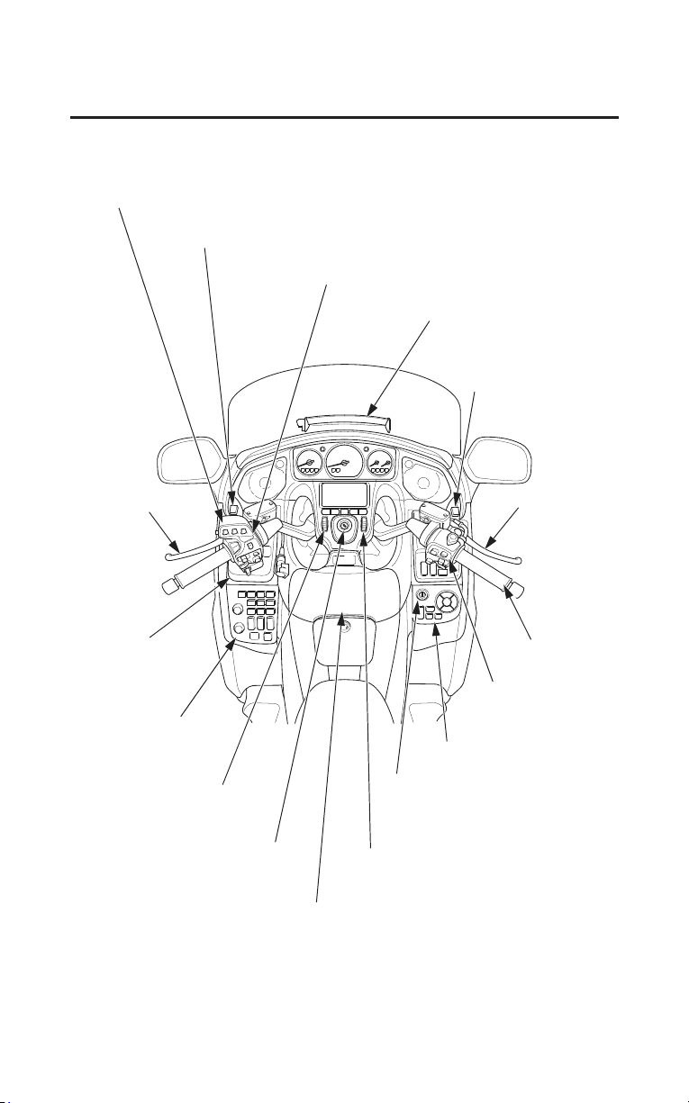
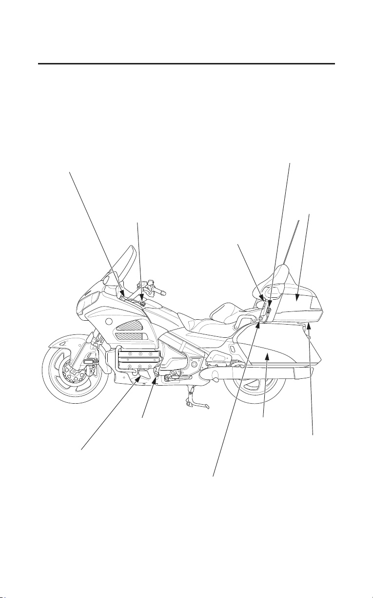
audio system controls
windscreen height lever
left handlebar controls
windscreen ventilation louver
windscreen
height lever
front brake
lever
clutch lever
throttle grip
handgrip heater
switch
right handlebar
controls
shelter case lock
(Models not equipped
with Airbag)
audio system
controls
front seat heater
switch
ignition switch
shelter case
(Models not equipped with Airbag)
right fairing panel controls
fairing pocket
12
Instruments & Controls
Operation Component Locations
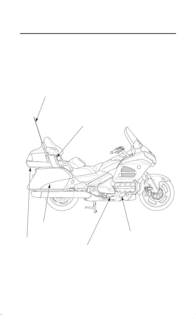
radio antenna
helmet holder
trunk side pocket
saddlebag
rear brake pedal
foot warmer ventilation louver
Instruments & Controls
13
Operation Component Locations
front headset terminal
trunk
rear headset terminal
trunk side pocket
shift lever
helmet holder
foot warmer ventilation louver lever
rear seat heater switch
foot warmer ventilation louver
saddlebag
14
Instruments & Controls
Operation Component Locations
Instruments & Controls
15
Gauges & Indicators
The gauges and indicators on your motorcycle keep you informed, alert you to
possible problems, and make your riding safer and more enjoyable. Refer to the
gauges and indicators frequently. Their functions are described on the following
pages.
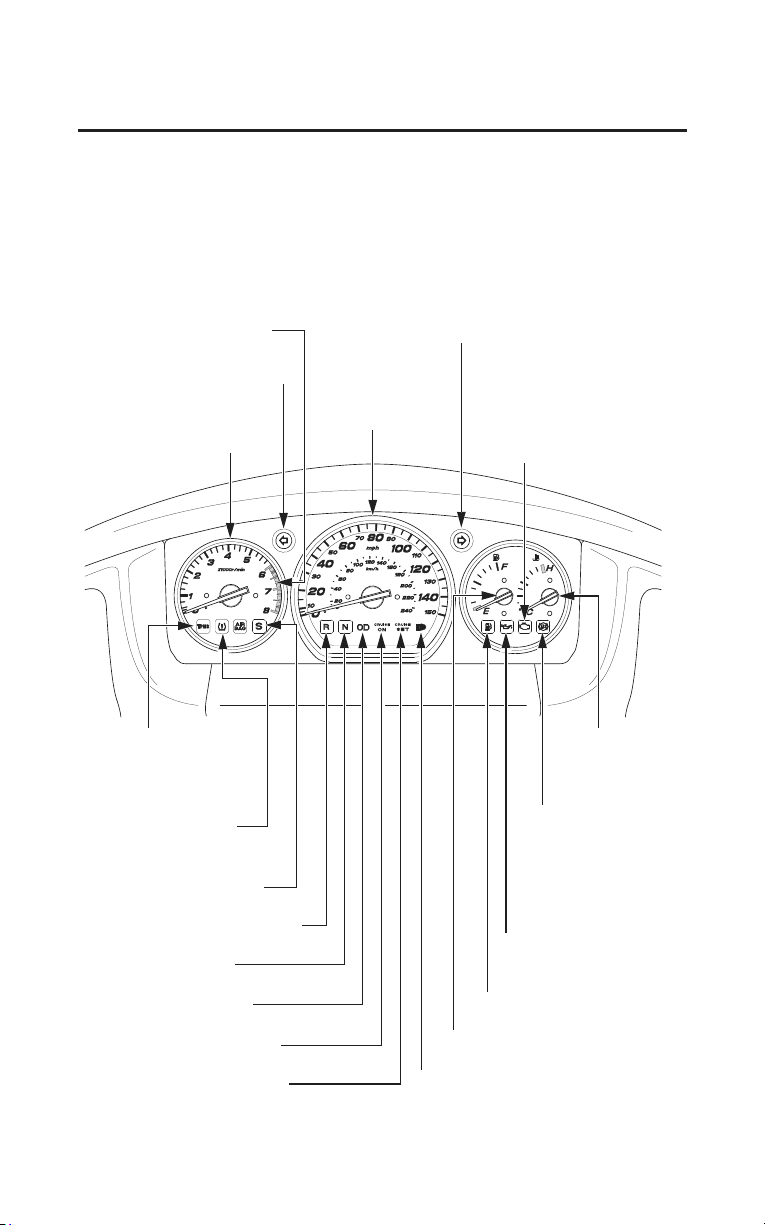
USA: Speedometer, odometer & tripmeter read in miles.
Canada: Speedometer, odometer & tripmeter read in kilometers.
tachometer red zone
tachometer
reverse system indicator
neutral indicator
overdrive indicator
CRUISE ON indicator
CRUISE SET indicator high beam indicator
fuel gauge
speedometer
right turn signal indicator
left turn signal indicator
PGM-FI malfunction
indicator lamp (MIL)
coolant
temperature
gauge
low oil pressure
indicator
low tire pressure
indicator
side stand indicator
low fuel indicator
anti-lock brake
system (ABS)
indicator (Models
equipped with
ABS)
tire pressure
monitoring system
(TPMS) indicator
16
Instruments & Controls
Gauges & Indicators
Lamp Check
Most of the indicator lights come on when you turn the ignition switch ON so
you can check that they are working. Some indicators turn off after a few
seconds; others remain on until or after the engine is started. The ABS indicator
goes off after you ride the motorcycle at a speed above 6 mph (10 km/h).
All indicators are identified on the following pages with the words:
Lamp Check.
When applicable, the high beam and neutral indicators come on when you turn
the ignition switch ON and remain on until you select the low beam or shift out
of neutral.
If one of these indicators does not come on when it should, have your dealer
check for problems.
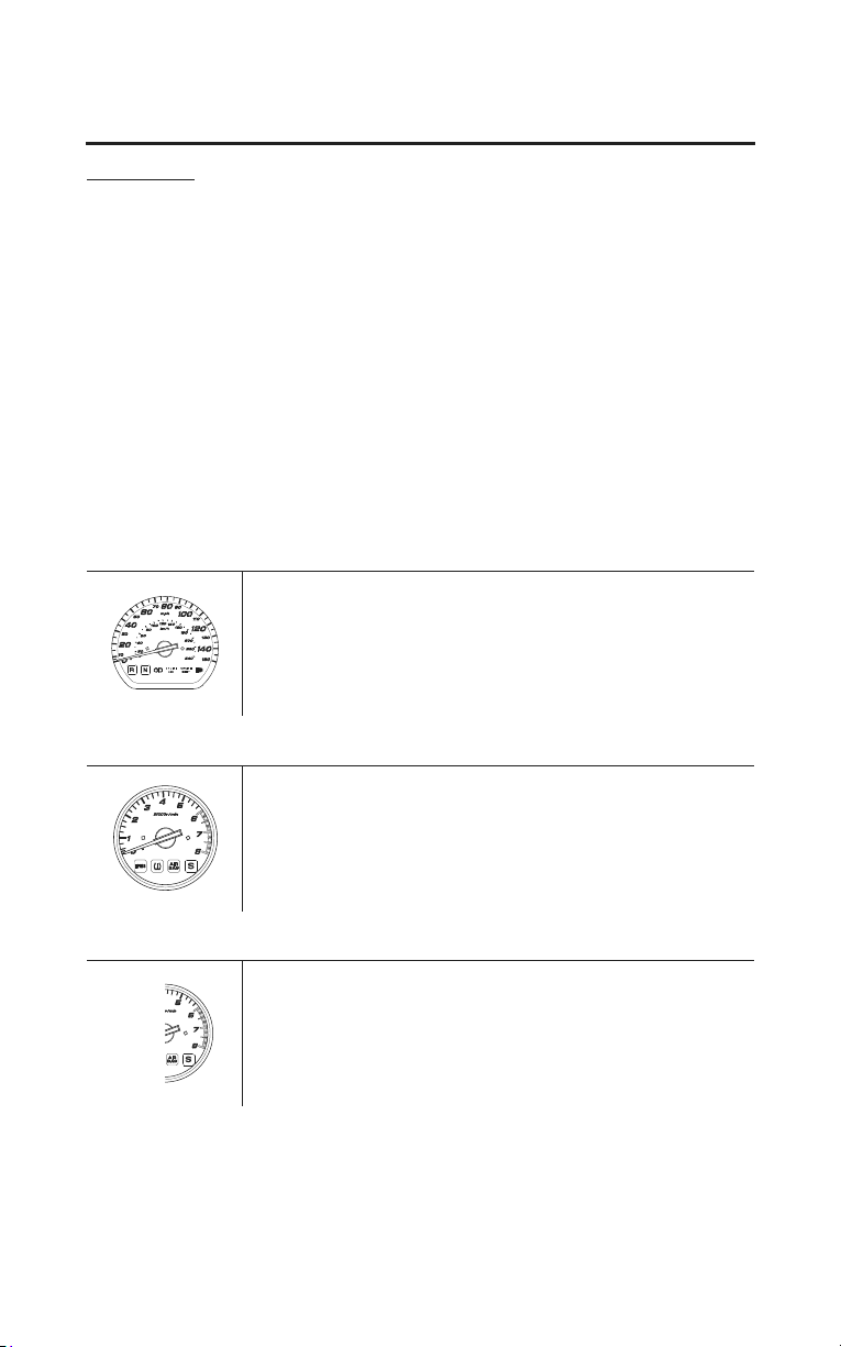
speedometer
Shows riding speed in miles (USA) or kilometers (Canada) per hour.
tachometer
Shows engine speed in revolutions per minute (rpm).
tachometer red zone
Shows excessive engine rpm range (indicated from the beginning of the
tachometer red zone) in which operation may damage the engine. Do not let the
tachometer needle enter the red zone.
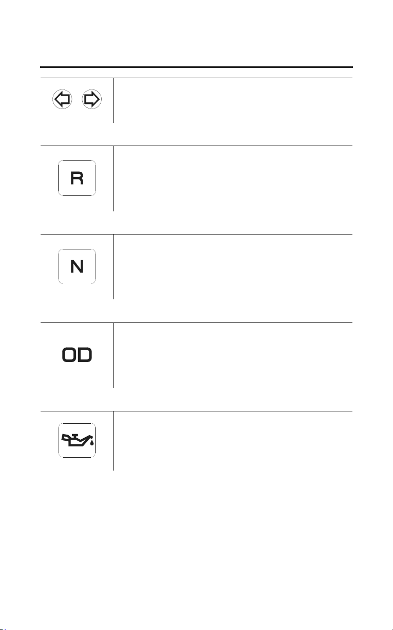
turn signal indicator (green)
Instruments & Controls
17
Gauges & Indicators
Flashes when either turn signal operates.
reverse system indicator (amber)
Lights when the reverse system is engaged.
neutral indicator (green)
Lights when the transmission is in neutral.
overdrive indicator (amber)
Lights when the transmission is in overdrive (5th gear).
low oil pressure indicator (red)
Lights when engine oil pressure is low enough to cause engine damage. If the
low oil pressure indicator lights during operation, pull safely to the side of the
road. See page 243 for instructions and cautions. Lamp Check.
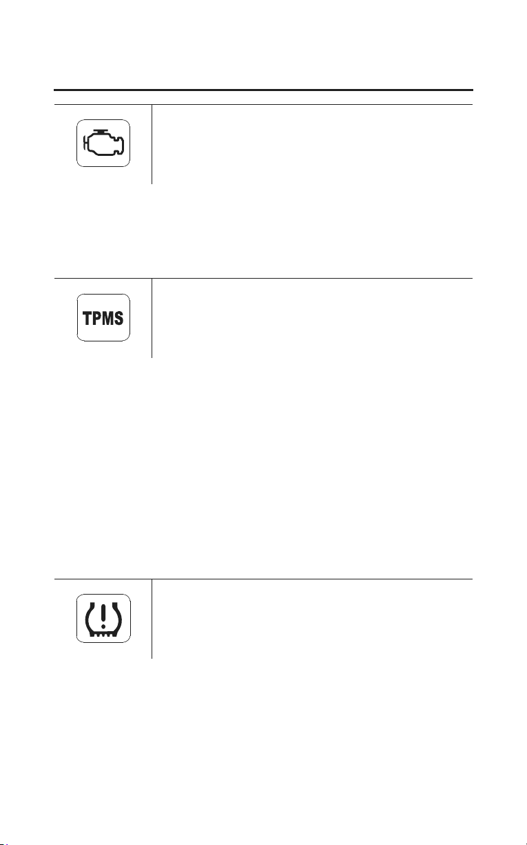
PGM-FI malfunction indicator lamp (MIL) (amber)
18
Instruments & Controls
Gauges & Indicators
Lights when there is any abnormality in the PGM-FI (Programmed Fuel
Injection) system. Should also light for a few seconds and then go off when the
ignition switch is turned ON and the engine stop switch is at RUN. If the
indicator comes on at any other time, reduce speed and take your motorcycle to
your dealer as soon as possible. Lamp Check.
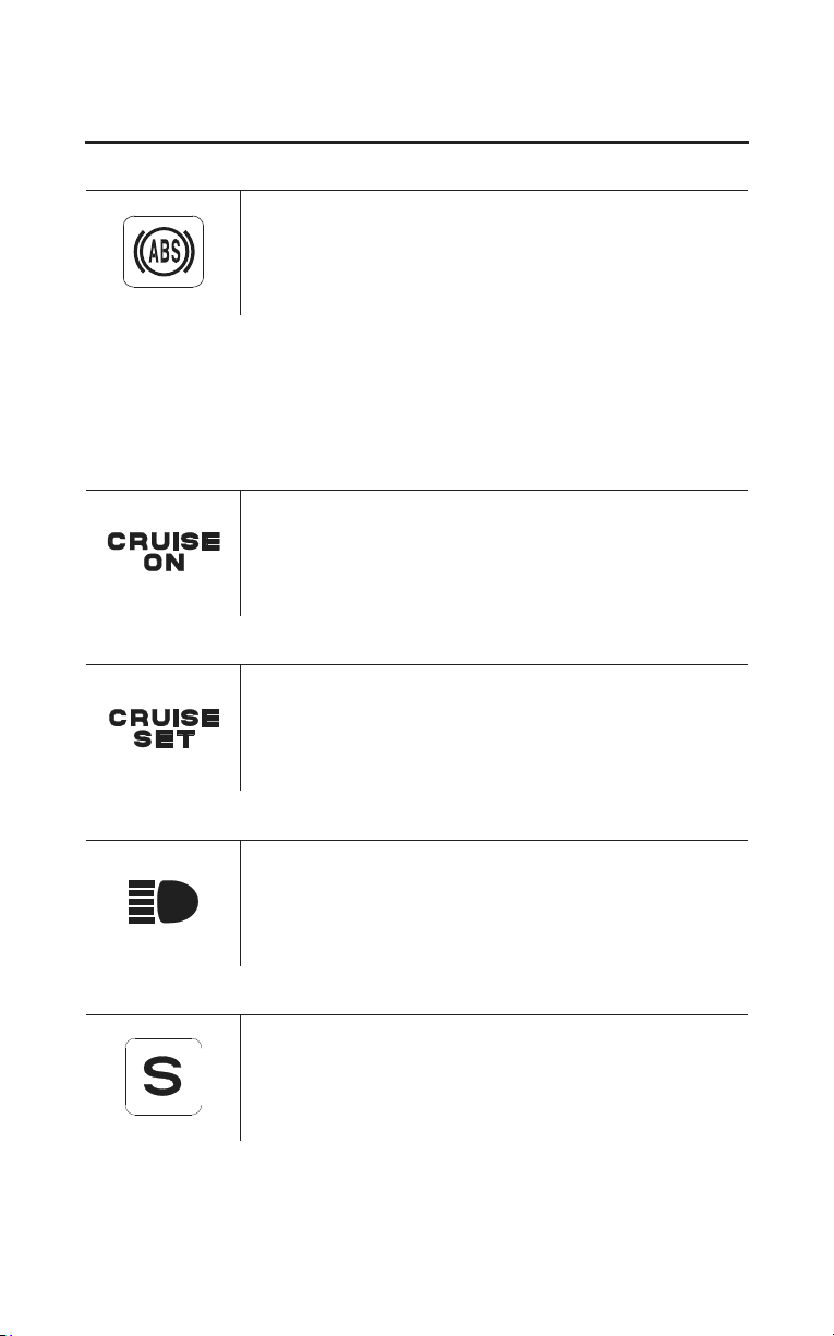
tire pressure monitoring system (TPMS) indicator
(amber)
Lights when there is any abnormality in the tire pressure monitoring system
(TPMS). Should also light for a few seconds and then go off when the ignition
switch is turned ON. See page 83 for instructions and cautions. Lamp Check.
If the indicator turns on and stays on at any other time, there is a problem with
the TPMS, and the indicator will remain on until the problem is solved.
Or if the TPMS indicator does not turn on when you turn the ignition switch to
ON, it is possible there is a problem and it will not turn on until the problem is
solved.
With this indicator on, the low tire pressure indicator will not come on when a
tire loses pressure, take the motorcycle to your dealer to have the system
checked.
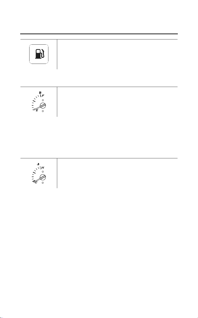
low tire pressure indicator (amber)
Flashes or lights when one or more of your motorcycle tires are significantly
low on pressure. Should also light for a few seconds and then go off when the
ignition switch is turned ON. If the indicator comes on while riding, stop the
motorcycle in a safe place and check the front and rear tires for inflation.
See page 83 for instructions and cautions. Lamp Check.
Instruments & Controls
19
Gauges & Indicators
(Models equipped with ABS)
Anti-Lock Brake System (ABS) indicator (amber)
Lights when there is any abnormality in the anti-lock brake system (ABS).
Normally, this indicator comes on when the ignition switch is turned ON, and
goes off after you ride the motorcycle at a speed above 6 mph (10 km/h). If the
indicator comes on while riding, stop the motorcycle in a safe place and turn off
the engine. Refer to ABS Indicator Light, page 81. For information about ABS,
see page 80. Lamp Check.
CRUISE ON indicator (amber)
Lights when the CRUISE CONTROL master switch is on.
CRUISE SET indicator (green)
Lights when the cruise control SET/DECEL switch is on.
high beam indicator (blue)
Lights when the headlight is on high beam.
side stand indicator (amber)
Lights when the side stand is put down – to indicate that the side stand ignition
cut-off system (page 71) is activated.
low fuel indicator (amber)
20
Instruments & Controls
Gauges & Indicators
Lights as a reminder to refuel soon. The indicator comes on when there is about
1.16 US gal (4.4 liters) left in the fuel tank. Lamp Check.
fuel gauge
Shows the approximate fuel supply available, if your motorcycle is on a level
surface.
At F (Full) there are 6.6 US gal (25 liters), including reserve supply. When the
gauge needle enters the red band, fuel will be low and you should refill the tank
as soon as possible. The amount of fuel left in the tank when the needle enters
the red band is approximately 0.79 US gal (3.0 liters).
coolant temperature gauge
Shows engine coolant temperature. When the needle moves above the C (cold)
mark, the engine is warm enough to start riding. If the needle approaches the H
(hot) mark, pull safely to the side of the road. See page 241 for instructions and
cautions.
Instruments & Controls
21
Multi Information Display
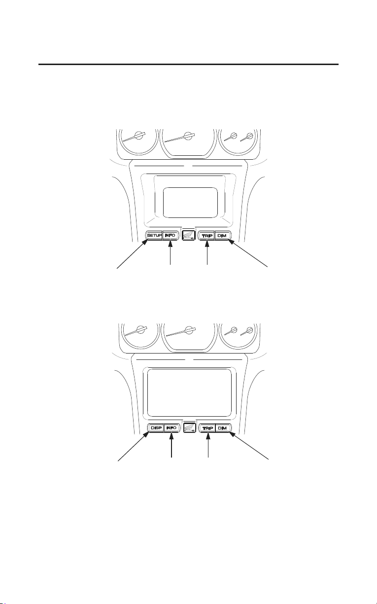
Your motorcycle is equipped with a Multi Information Display that presents
various displays. This section explains display functions and operations.
SETUP button INFO button TRIP button DIM button
(Models not equipped with Navigation System)
(Models equipped with Navigation System)
DISP button
INFO button TRIP button DIM button
The Opening/Ending Ceremony and Clock can be set with the Setup/Info Menu
of the Navigation System. Refer to the Navigation System Manual for further
information.
22
Instruments & Controls
Multi Information Display
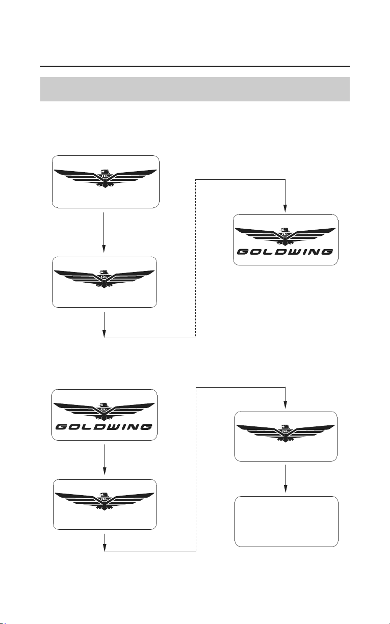
Opening/Ending Ceremony
(Models not equipped with Navigation System)
When the ignition switch is turned ON or ACC, the display presents an
‘‘opening ceremony.’’
When the ignition switch is turned OFF, the display presents an ‘‘ending
ceremony.’’
Instruments & Controls
23
Multi Information Display
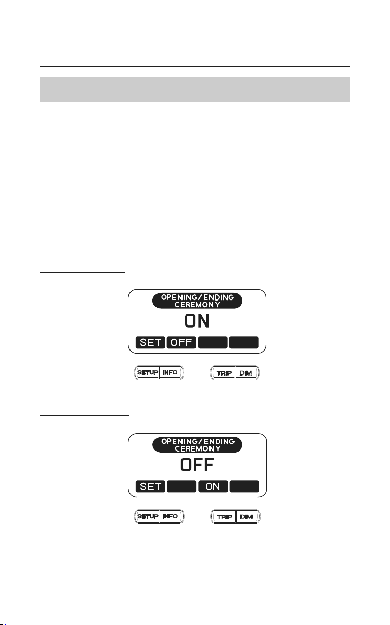
On/Off-Opening/Ending Ceremony
(Models not equipped with Navigation System)
The opening/ending ceremony can be turned off.
1. Push the SETUP button to show the CLOCK ADJUST display (page 30).
2. Push the DIM button to show the OPENING/ENDING CEREMONY
display.
3. Push the TRIP or INFO button to switch ON/OFF.
4. Push the SETUP button to fix the setting.
When approximately 5 seconds pass without operating a button on the
OPENING/ENDING CEREMONY display, the display automatically returns to
the previous display.
ceremony display ON
ceremony display OFF
24
Instruments & Controls
Multi Information Display
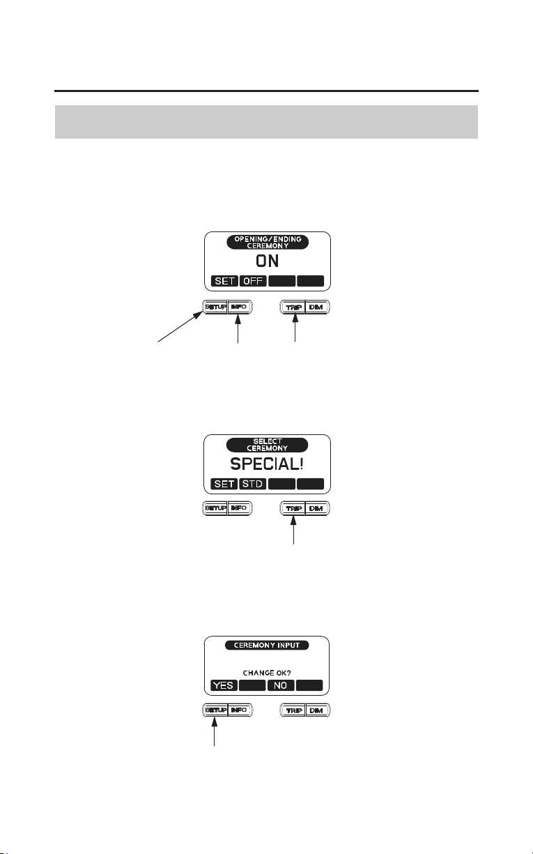
Special Message for Opening/Ending Ceremony
(Models not equipped with Navigation System)
1. Select ‘‘ON’’ on the OPENING/ENDING CEREMONY display (page 23).
2. Push and hold the TRIP button and INFO button for a while. Then push the
SETUP button.
INFO button TRIP buttonSETUP button
3. The display should now show ‘‘STANDARD’’ in the middle line.
4. Use the TRIP button to select the ‘‘SPL’’ function.
The display should now show ‘‘SPECIAL!’’ in the middle line.
TRIP button
5. Push the SETUP button to select the ‘‘SET’’ function.
The display should now show ‘‘CHANGE OK?’’ in the middle line.
6. Push the SETUP button to select the ‘‘YES’’ function.
SETUP button
Instruments & Controls
25
Multi Information Display
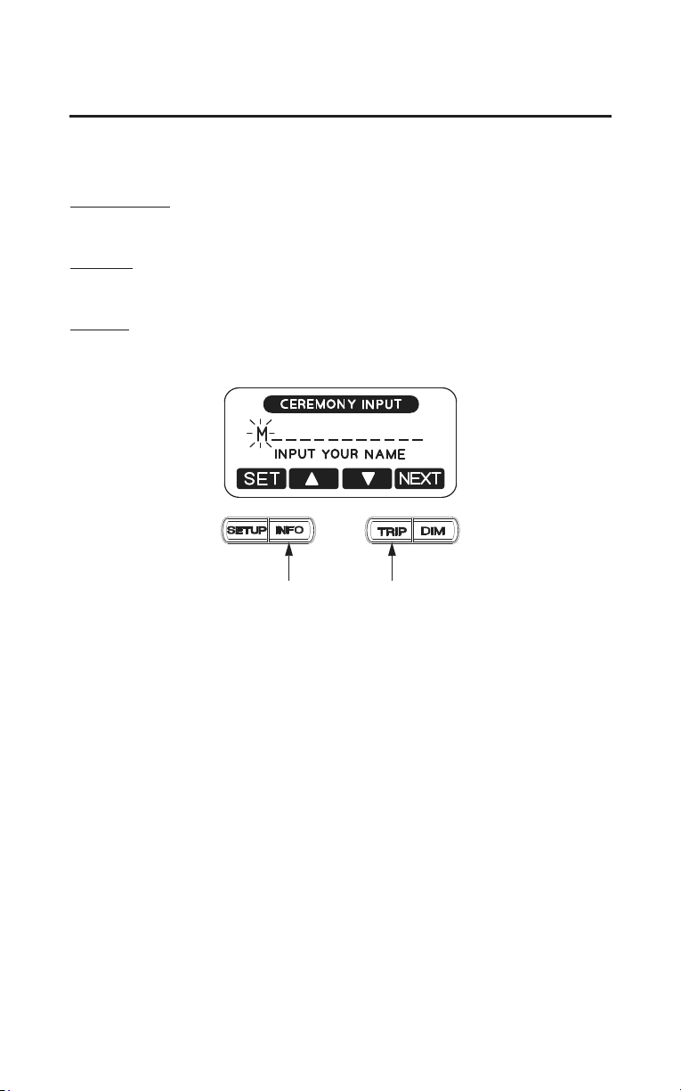
7. Use the INFO and TRIP buttons to cycle through the alphabet, number and
symbol selection.
Capital Letters
A B C D E F G H I J K L M N O P Q R S T U V W X Y Z
Numbers
0 1 2 3 4 5 6 7 8 9
Symbols
! ” # $ % & ’ ( ) * + , – . / > = < ?
INFO button TRIP button
8. When you have completed your message, push the SETUP button to select
the ‘‘SET’’ function which will lock in your special message to be used for
the opening and ending ceremony.
When approximately 5 seconds pass without operating a button, the display
automatically returns to the previous display.
26
Instruments & Controls
Multi Information Display
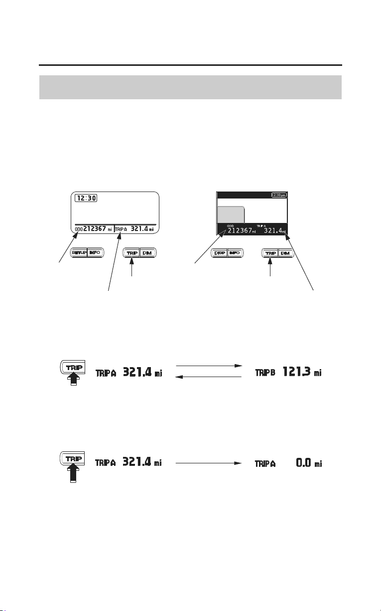
Odometer/Tripmeter
• ODO (Odometer) — shows the total miles (USA) or kilometers (Canada)
ridden.
• TRIP (Tripmeter) — shows the number of miles (USA) or kilometers (Canada)
ridden since you last reset the meter.
odometer
TRIP button
(Models not equipped with
Navigation System)
(Models equipped with
Navigation System)
TRIP button
tripmeter
odometer
tripmeter
The tripmeter will show mileage in two sub modes, ‘‘TRIP A’’ and ‘‘TRIP B.’’
Push the TRIP button to select the ‘‘TRIP A’’ or ‘‘TRIP B’’ mode.
To reset the tripmeter, push and hold the TRIP button with the display in the
‘‘TRIP A’’ or ‘‘TRIP B’’ mode.
Instruments & Controls
27
Multi Information Display
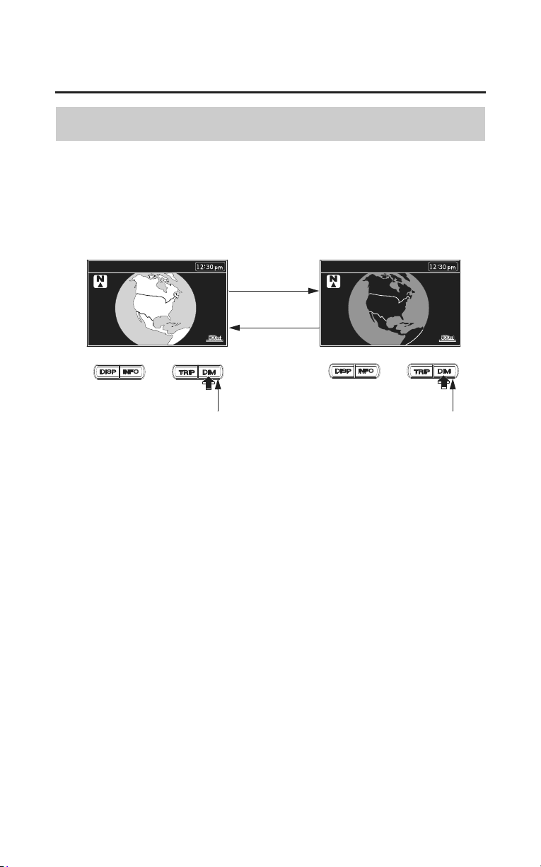
Switch the Day Mode Display and Night Mode Display
(Models equipped with Navigation System)
The display automatically switches to the Day mode or Night mode in
accordance with the time. To switch the display manually, push and hold the
DIM button.
Refer to the Navigation System Manual for further information.
DIM button DIM button
28
Instruments & Controls
Multi Information Display
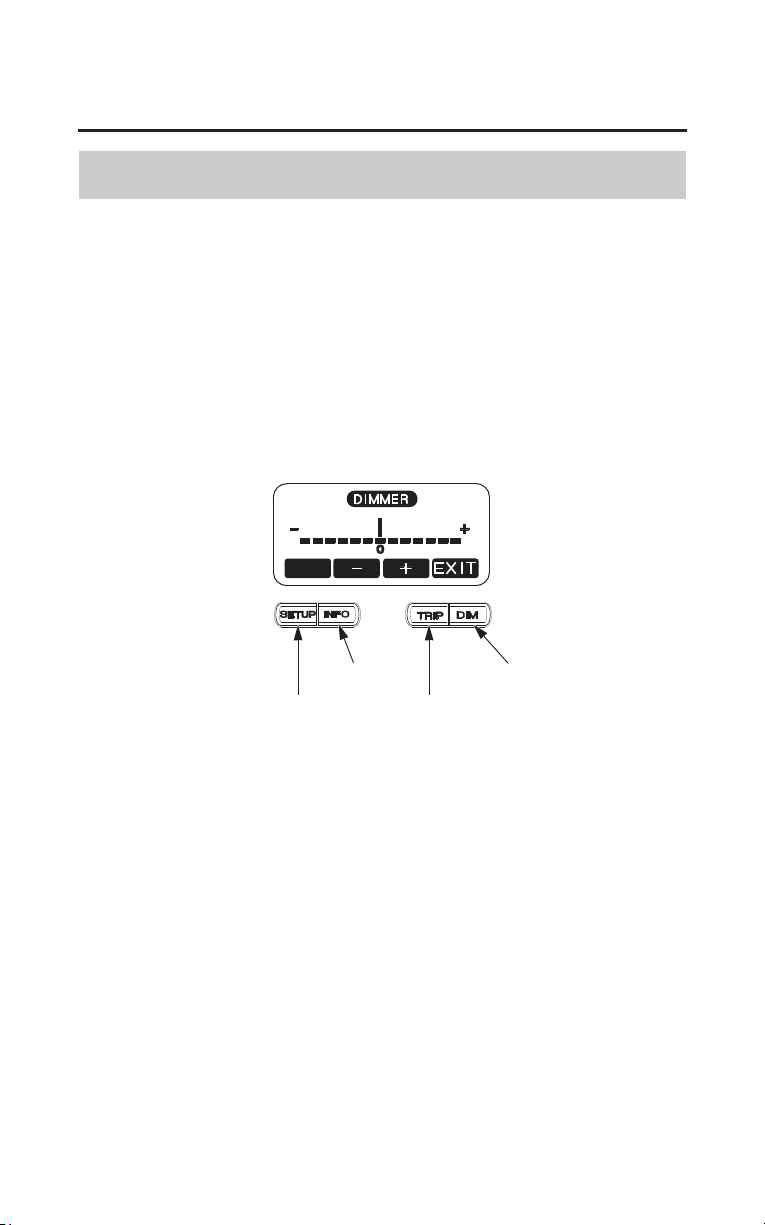
Display Illumination Adjustment
(Models not equipped with Navigation System)
To adjust the brightness of the display:
Push the DIM button once. ‘‘DIMMER’’ will display.
• To brighten the display — push the TRIP button (+).
• To darken the display — push the INFO button (–).
(The brighter and darker ranges each have six steps.)
• To set the selected step — push the SETUP button.
SETUP button
TRIP button
DIM button
INFO button
Instruments & Controls
29
Multi Information Display
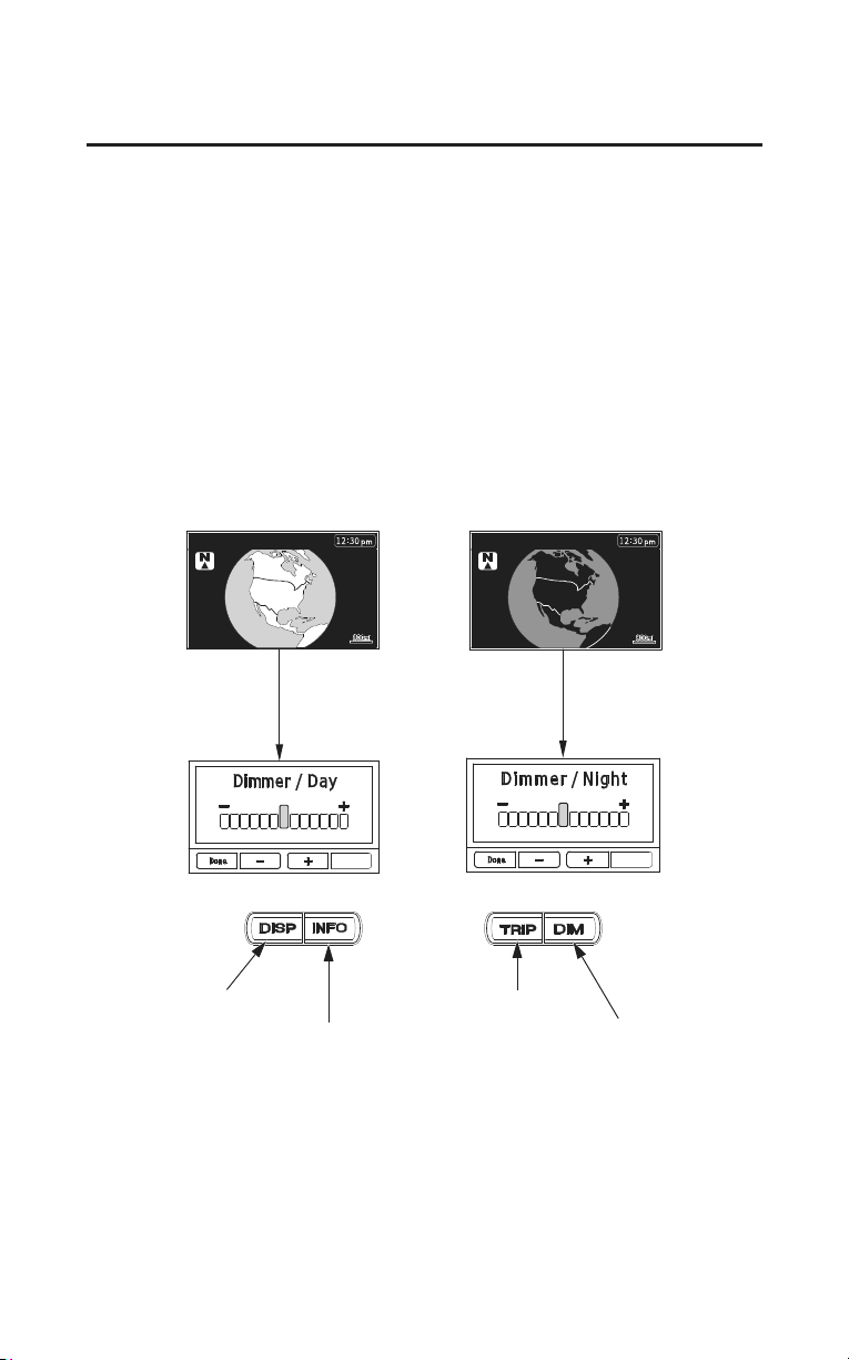
(Models equipped with Navigation System)
To adjust the brightness of the display:
Push the DIM button once. The display shows ‘‘Dimmer/Day’’ at Day mode,
while it shows ‘‘Dimmer/Night’’ at Night mode.
• To brighten the display — push the TRIP button (+).
• To darken the display — push the INFO button (–).
(The brighter and darker ranges each have six steps.)
• To set the selected step — push the DISP button.
To switch the display between ‘‘Dimmer/Day’’ and ‘‘Dimmer/Night’’, select the
display be
tween Day mode and Night mode (page 27) and push the DIM button.
INFO button
TRIP button
DIM button
DISP button
When approximately 5 seconds pass without operating a button, the display
automatically returns to the previous display.
The display can become dark when the display is very hot. If it does not restore
the original brightness, consult your dealer.

30
Instruments & Controls
Multi Information Display
Digital Clock
(Models not equipped with Navigation System)
The display shows the hour and minute.
To adjust the time:
1. Turn the ignition switch to ON or ACC.
2. Push the SETUP button once. ‘‘CLOCK ADJUST’’ will display.
3. To set the hour, press and release the INFO button until the desired hour
appears.
• Quick setting — push and hold the INFO button until the desired hour
appea
rs.
4. To set the minute, press and release the TRIP button until the desired minute
appears.
• Quick setting — push and hold the TRIP button until the desired minute
appears.
5. Once the time is selected, push the SETUP button to enter the time.
When approximately 5 seconds pass without operating a button on the CLOCK
ADJUST display, the display automatically returns to the previous display.
Be sure to push the SETUP button to enter your adjusted time in the system.
SETUP button
TRIP buttonINFO button
(Models equipped with Navigation System)
The navigation system receives signals from the Global Positioning System
(GPS) and automatically sets the time display based on the time zone you select.
You may also set the time manually using the ‘‘Other’’ option. Refer to the
Navigation System Manual.
Instruments & Controls
31
Multi Information Display
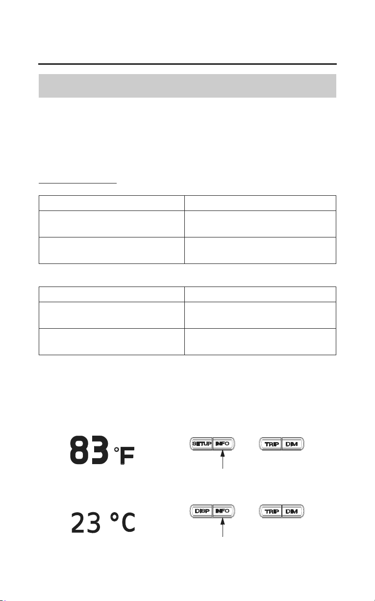
Air Temperature Meter
Push the INFO button once to display the air temperature.
After 5 seconds, the previous display returns.
USA: Fahrenheit (°F)
Canada: Centigrade (°C)
Temperature Display
Below 13°F (–11°C) ‘‘- -’’ is displayed
Between:
14°F – 122°F (–10°C – 50°C)
actual air temperature is indicated
Above 122°F (50°C) The display will remain and blink
‘‘122°F (50°C)’’
(Models not equipped with Navigation System)
Below 13°F (–11°C) ‘‘- -’’ is displayed
Between:
14°F – 158°F (–10°C – 70°C)
actual air temperature is indicated
Above 158°F (70°C) The display will remain
‘‘158°F (70°C)’’
(Models equipped with Navigation System)
The temperature sensor is located in the upper fairing. Therefore, the
temperature reading can be affected by heat reflection from the road surface,
engine heat, and the exhaust from the surrounding traffic. This can cause an
error in the temperature reading when your speed is under 19 mph (30 km/h).
For USA
For Canada
(Models not equipped with Navigation System)
INFO button
INFO button
(Models equipped with Navigation System)
32
Instruments & Controls
Multi Information Display
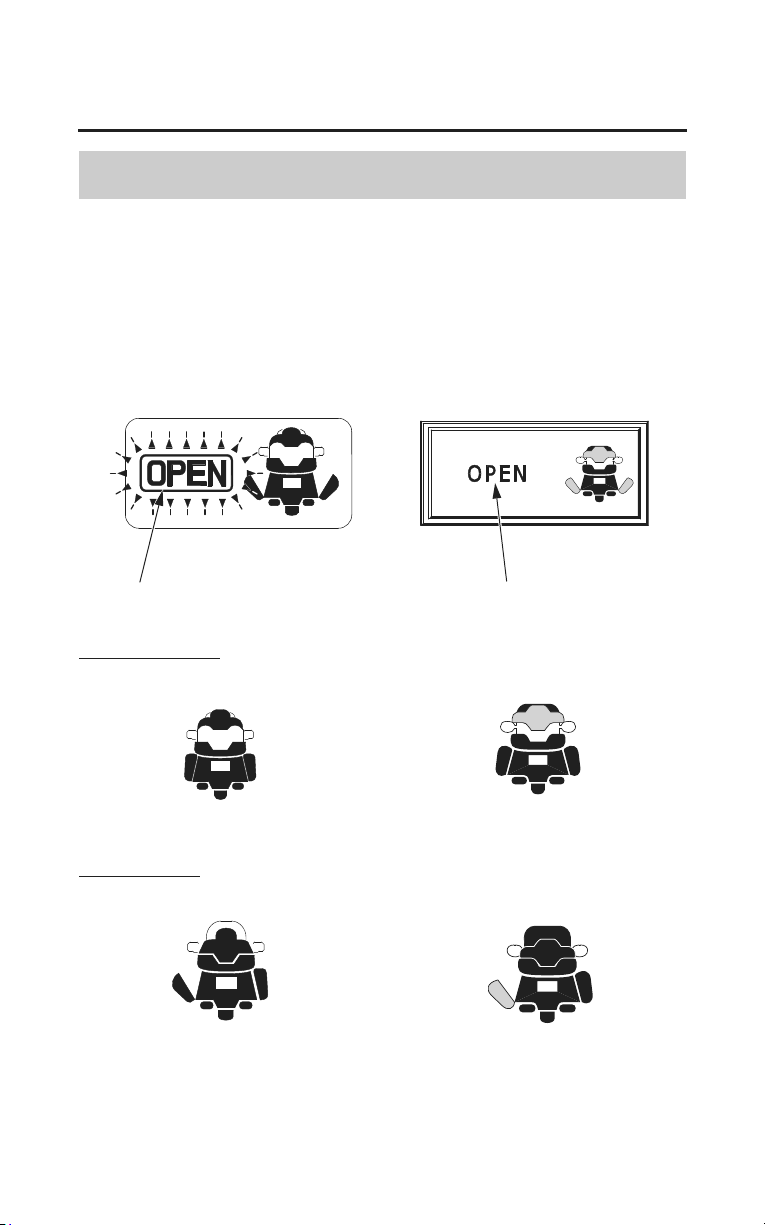
Travel Trunk & Saddlebags Open Indicator
This indicator turns on when the ignition switch is ON and your motorcycle’s
travel trunk or saddlebags are open.
If all compartments are not fully closed, the display will blink OPEN and
indicate the open compartment(s).
open indicator open indicator
(Models not equipped with
Navigation System)
(Models equipped with
Navigation System)
Travel Trunk open
Saddlebag open
Instruments & Controls
33
Multi Information Display
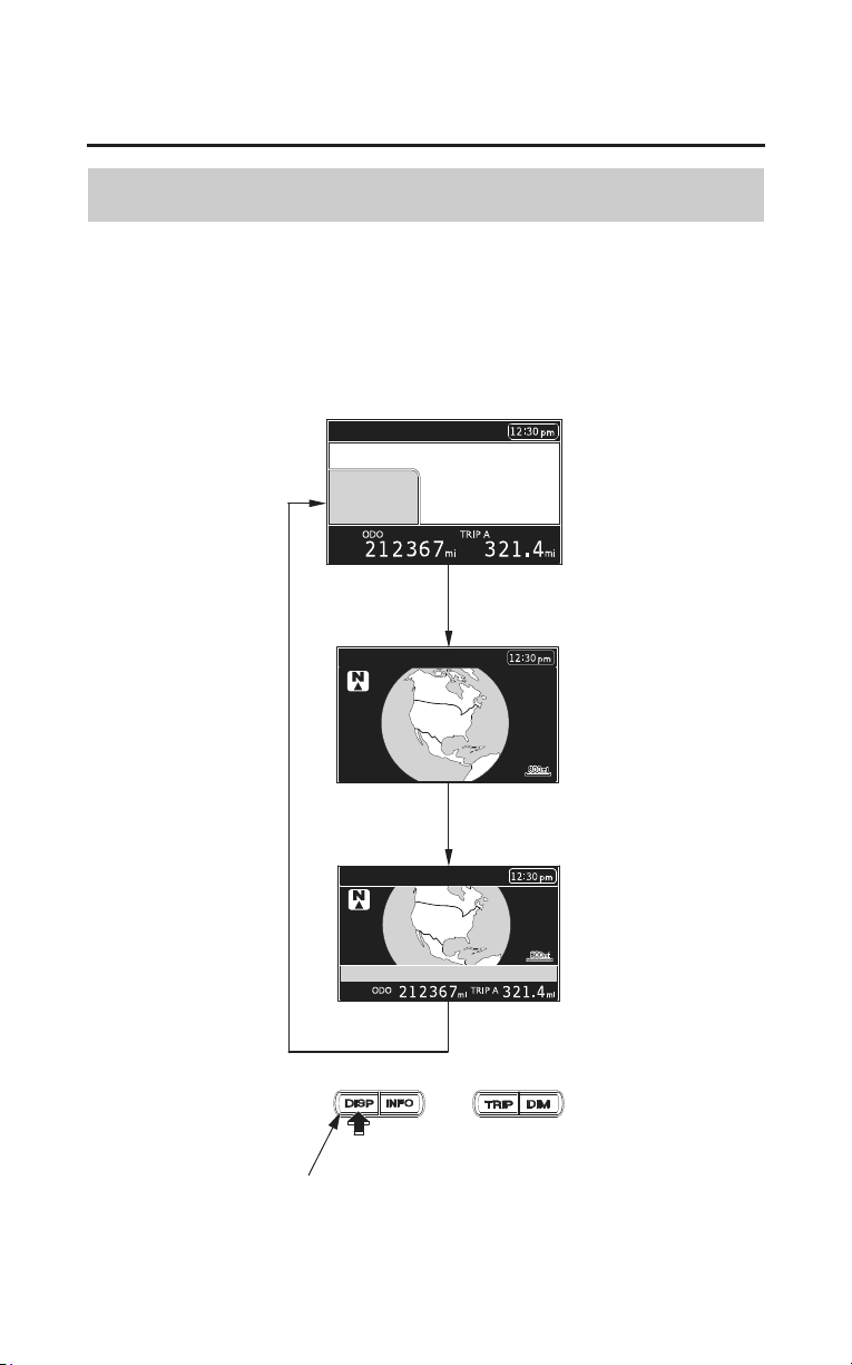
Display Type Selection
(Models equipped with Navigation System)
Press the DISP button to toggle between:
• The Multi Information Display (time, odometer, and tripmeter)
• A Navi full screen map with the time
• A split screen with the Multi information condensed in a bar below the map.
DISP button
34
Instruments & Controls
Multi Information Display
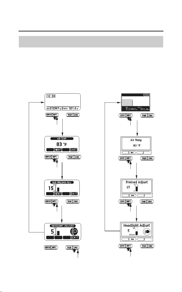
Changing the Information Display
The display changes as follows each time the INFO button is pushed.
When approximately 5 seconds pass without operating a button, the display
automatically returns to the previous display.
INFO button
INFO button
INFO button
INFO button
INFO button
DIM button
INFO button
INFO button
(Models not equipped with
Navigation System)
(Models equipped with
Navigation System)
Instruments & Controls
35
Controls & Features
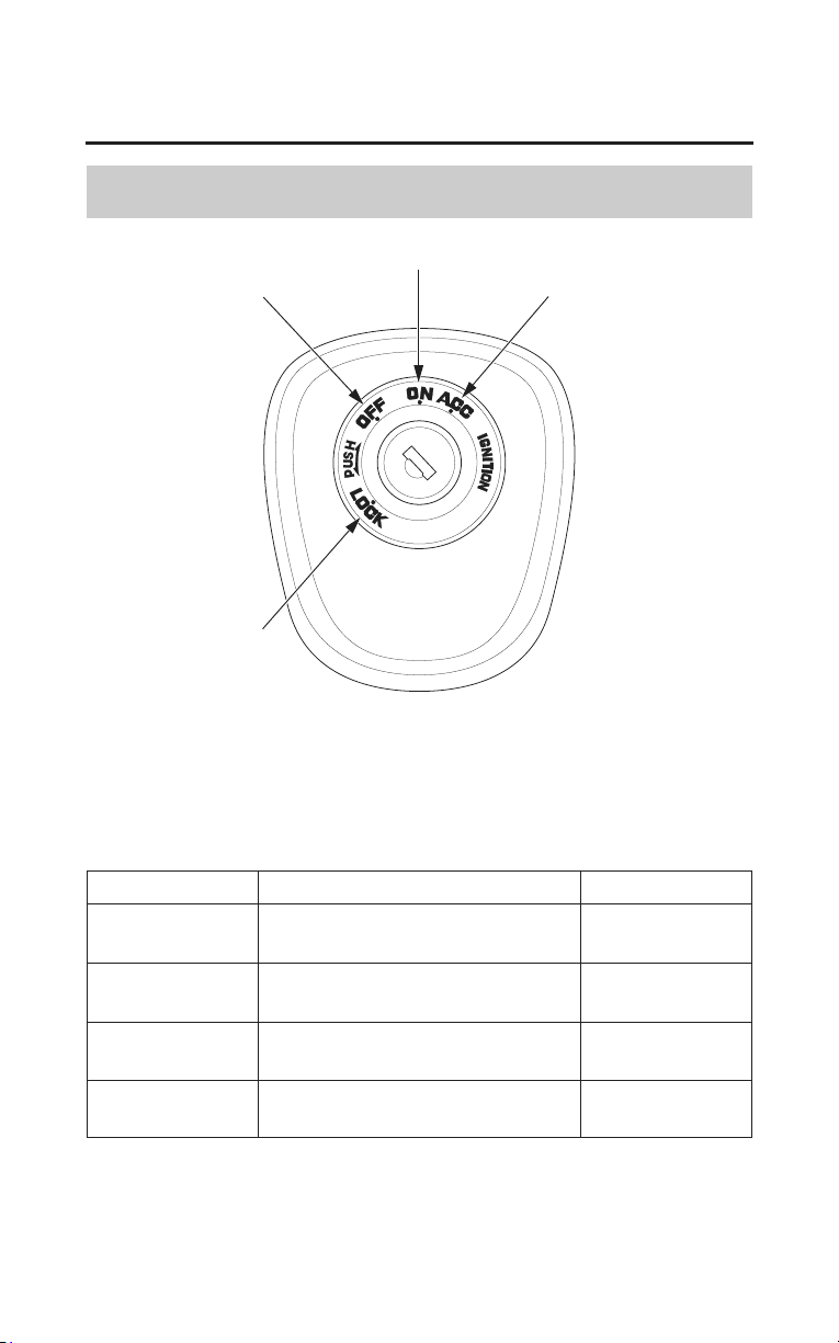
Ignition Switch
ON
ACC
LOCK
OFF
The ignition switch is used for starting and stopping the engine (page 71) and to
lock the steering for theft prevention (page 87). Insert the key and turn it to the
right for the ON and ACC (accessory) positions.
Push down on the key and turn it to the left to the LOCK (steering lock)
position.
Key Position Function Key Removal
ACC Only the accessory circuits
function.
cannot be
removed
ON Electrical circuits on. cannot be
removed
OFF No electrical circuits function. can be
removed
LOCK
(steering lock)
No electrical circuits function.
Locks the steering head.
can be
removed
To unlock the steering lock, insert and push down on the key and turn it to the
right to the OFF position.
36
Instruments & Controls
Controls & Features
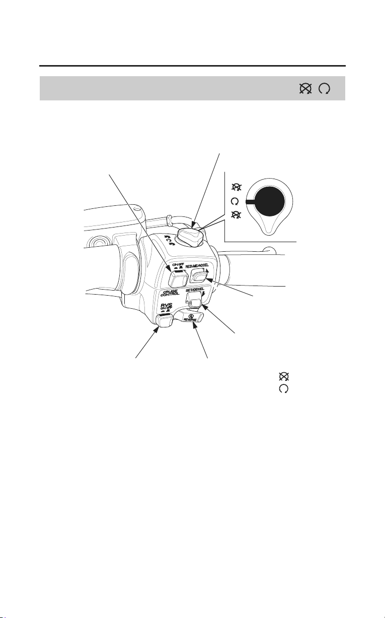
Engine Stop Switch
RIGHT HANDLEBAR
engine stop switch
reverse (RVS) switch start/reverse button
SET/DECEL switch
RESUME/ACCEL switch
CRUISE CONTROL master switch
OFF
RUN
The engine stop switch is used to stop the engine in an emergency. To operate,
turn the switch to the OFF position. The switch must be in the RUN position to
start the engine, and it should normally remain in the RUN position even when
the engine is OFF.
If your motorcycle is stopped with the ignition switch ON and the engine stop
switch OFF, the headlight and taillight will remain on, resulting in battery
discharge.

Instruments & Controls
37
Controls & Features
Start/Reverse Button
The start/reverse button is used for starting the engine. Pushing the start/reverse
button in starts the engine. See Starting Procedure, page 72.
When the start/reverse button is pushed, the starter motor will crank the engine;
the headlight will automatically go out, but the taillight will stay on.
The starter motor will not operate if the engine stop switch is in the OFF
position when the start/reverse button is pushed.
The start/reverse button is also used for reverse riding. See Riding in Reverse,
page 76.
Reverse (RVS) Switch
The reverse switch is used to shift into reverse gear so you may back up your
motorcycle. For instructions, see Riding in Reverse, page 76.
Cruise Control Switches
Three switches are used to activate, adjust, and de-activate the cruise control
system: a CRUISE CONTROL master switch, a SET/DECEL switch, and a
RESUME/ACCEL switch. For operating instructions, see Riding with Cruise
Control, page 91.
38
Instruments & Controls
Controls & Features
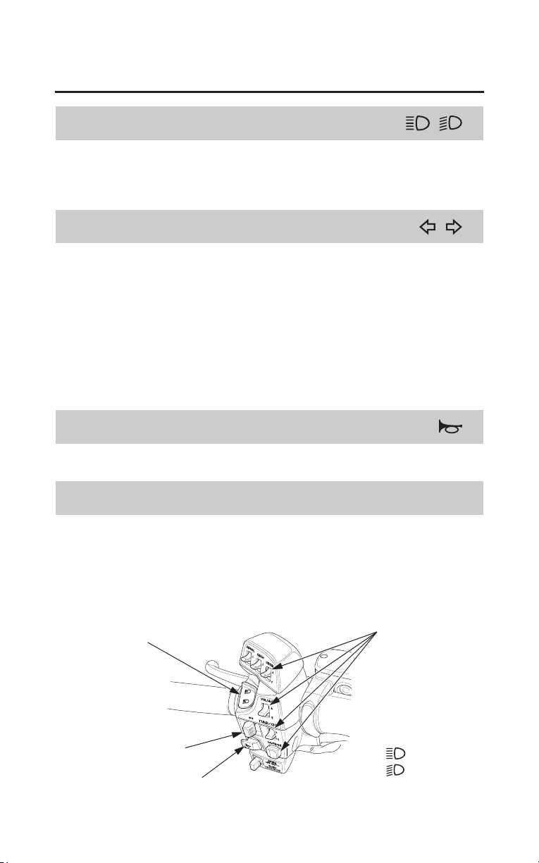
Headlight Dimmer Switch
The headlight dimmer switch is used to change between the high and low
headlight beams. To operate, push the button to HI for high beam, LO for low
beam.
Turn Signal Switch
The turn signal switch is used to signal a turn. To operate, move the switch all
the way to the left or right and release it.
The appropriate turn signal lights will start blinking. The lights will
automatically stop when you complete the turn. (You can manually cancel the
lights by pushing the switch in.)
To signal a lane change, move the switch all the way to the left or right and
release it. The turn signal lights will automatically stop in 7 seconds or after
riding 110 yards (120 m).
Horn Button
The horn is used to alert other motorists. To operate, push the button.
Audio Control Switches
The audio control switches mounted on the left handlebar and above the fuel fill
compartment are used to operate the radio. For specific features and operation
instructions, see Audio Systems, page 95.
LEFT HANDLEBAR
horn button
audio control switchs
headlight dimmer switch
turn signal switch
HI
LO
Instruments & Controls
39
Controls & Features
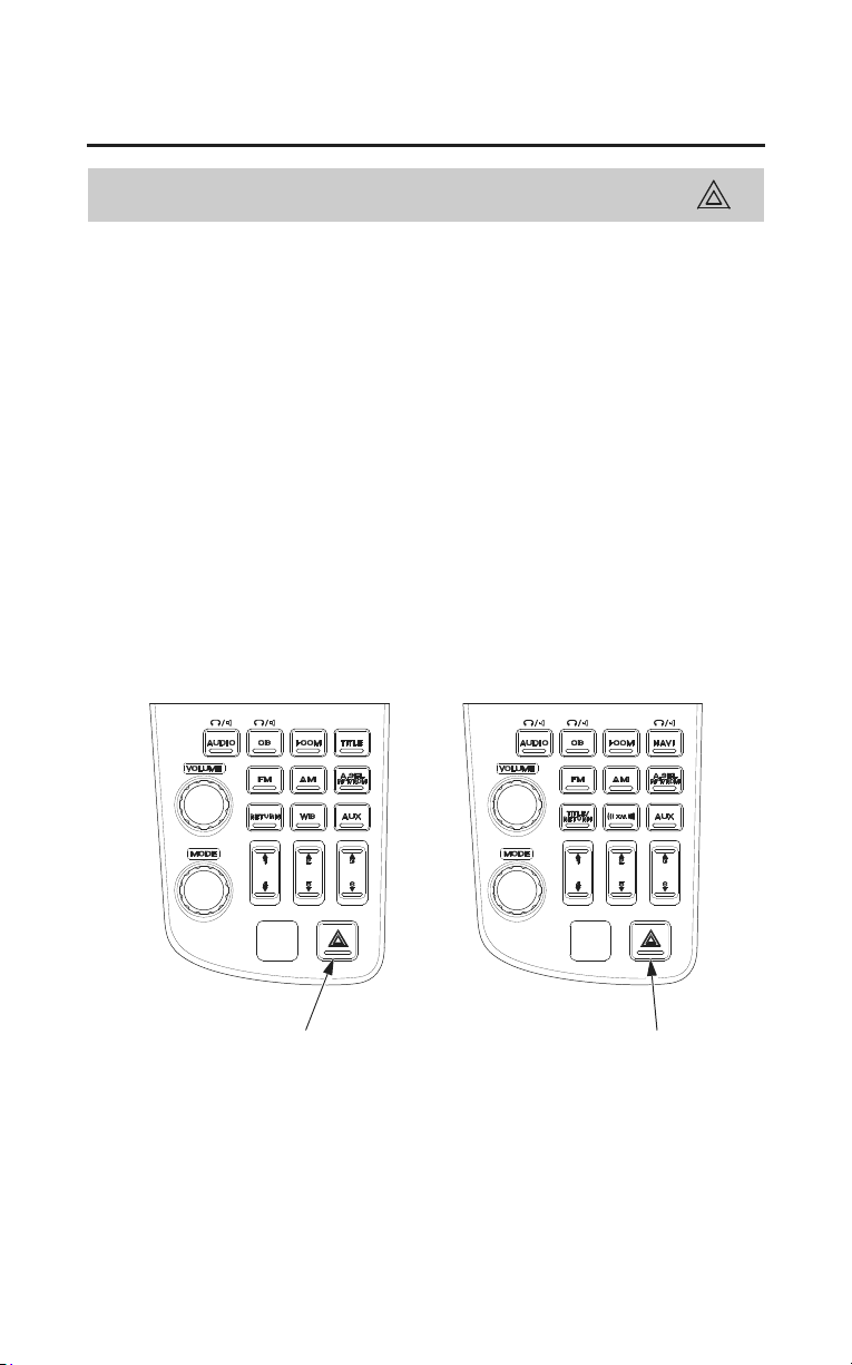
Hazard Switch
The hazard switch is used to activate the hazard lights on your motorcycle if you
need to stop near heavy traffic or if your motorcycle is disabled.
To operate, turn the ignition key to the ON or ACC position, and push the
hazard switch. The front and rear turn signals will blink simultaneously until
you push the switch again.
If you anticipate using the hazard system for an extended time, use the ACC
position and turn off all unnecessary accessories to conserve battery capacity.
Be sure to turn the switch off when the hazard warning is no longer required, or
the turn signals will not work properly and may confuse other drivers.
LEFT SIDE
(Models not equipped with
Navigation System)
hazard switch
(Models equipped with
Navigation System)
hazard switch
40
Instruments & Controls
Controls & Features
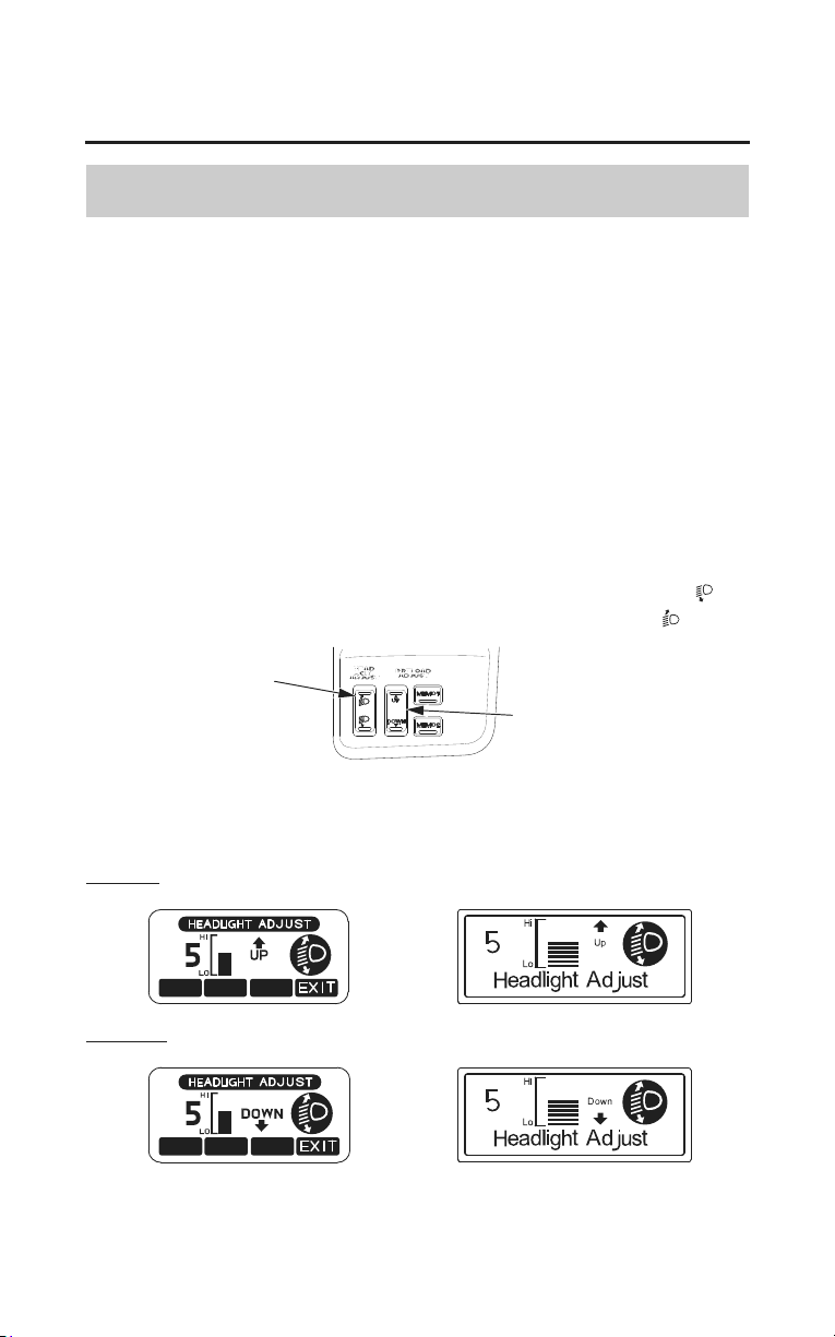
Headlight Beam Adjustment Switch
The adjustment switch is used to raise or lower the height of the headlight beam.
You can confirm the headlight beam position by referring to the multi
information display.
If you carry a heavier or lighter than normal load, you may need to adjust your
headlight beam so you can better see the road ahead and don’t blind oncoming
drivers. Obey local laws and regulations concerning headlight adjustment.
To operate, adjust the Headlight Beam Adjustment Switch when the engine is
started and your
motorcycle is stopped.
The headlight beam adjustment has 11 positions (from 0 to 10) for different
riding conditions. (Standard position is 10.)
To lower the beam, push the Headlight Beam Adjustment Switch down (
).
To raise the beam, push the Headlight Beam Adjustment Switch up (
).
headlight beam
adjustment switch
rear suspension spring
pre-load adjustment
switch
(Models not equipped with
Navigation System)
(Models equipped with
Navigation System)
To Raise
To Lower
When approximately 5 seconds pass without operating the Headlight Beam
Adjustment Switch, the display automatically returns to the previous display.

Instruments & Controls
41
Controls & Features
Rear Suspension Spring Pre-load Adjustment Switch
The rear suspension spring pre-load adjustment switch is used to adjust the rear
suspension to suit your load and riding conditions. For instructions on when and
how to adjust the rear suspension, see Rear Suspension Spring Pre-load
Adjustment, page 192.
Ventilation Controls
The windscreen ventilation louver is used to direct the flow of fresh air
(page 63).
The foot warmer ventilation louvers are used to direct the flow of warm air
(page 64).
Windscreen Height Adjustment
The windscreen height adjustment levers are used to raise or lower your
windscreen to suit your riding preference. For instructions, see page 62.

Before Riding
43
Before Riding
Before each ride, you need to make sure you and your Honda are both ready to
ride. To help get you prepared, this section discusses how to evaluate your
riding readiness, what items you should check on your motorcycle, and
adjustments to make for your comfort, convenience, or safety. This section also
includes important information about loading.
For information about adjusting the suspension on your Honda, see page 193.
Are You Ready to Ride?.................................................................................... 44
Pr
otective Apparel ........................................................................................ 44
Rider Training ............................................................................................... 46
Is Your Motorcycle Ready to Ride?..................................................................47
Pre-ride Inspection........................................................................................ 47
Load Limits & Guidelines................................................................................. 49
Loading .........................................................................................................49
Load Limits................................................................................................... 50
Loading Guidelines....................................................................................... 51
Cargo Compartment ..........................................................................................52
Travel Trunk & Saddlebags ..........................................................................52
Remote Transmitter....................................................................................... 55
Fairing Pocket / Shelter Case........................................................................ 59
Trunk Side Pockets ....................................................................................... 60
Comfort & Convenience Adjustment................................................................61
Windscreen Height Adjustment .................................................................... 62
Windscreen Ventilation Louver..................................................................... 63
Foot Warmer Ventilation Louvers................................................................. 64
Handgrip Heater............................................................................................ 65
Seat Heater ....................................................................................................66
Accessories........................................................................................................67
Accessory (ACC) Terminal........................................................................... 67

44
Before Riding
Are You Ready to Ride?
Before you ride your motorcycle for the first time, we urge you to:
• Read this owner’s manual.
• Make sure you understand all the safety messages.
• Know how to operate all the controls.
Before each ride, be sure:
• You feel well and are in good physical and mental condition.
• You are wearing an approved motorcycle helmet (with chin strap tightened
sec
urely), eye protection, and other protective clothing.
• You don’t have any alcohol or drugs in your system.
Make sure your passenger is ready to ride, too, and is wearing proper gear
including a helmet.
If you are not riding with a passenger and want to carry an extra helmet, use a
commercially-available elastic cord, strap, or net to secure the helmet to the
seat.
The travel trunk may also be used to store an extra helmet.
Protective Apparel
For your safety, we strongly recommend that you always wear an approved
motorcycle helmet, eye protection, boots, gloves, long pants, and a long-sleeved
shirt or jacket whenever you ride.
Although complete protection is not possible, wearing proper gear can reduce
the chance of injury when you ride.
Following are suggestions to help you choose the proper gear.
Before Riding
45
Are You Ready to Ride?
Helmet and Eye Protection
Your helmet is your most important piece of riding gear because it offers the
best protection against head injuries. A helmet should fit your head comfortably
and securely. A bright-colored helmet and reflective strips can make you more
noticeable in traffic.
An open-face helmet offers some protection, but a full-face helmet offers more.
Regardless of the style, look for a DOT (Department of Transportation) sticker
on any helmet you buy (USA only). Always wear a face shield or goggles to
protect your eyes and help your vision.
Not wearing a helmet increases
the chance of serious injury or
death in a crash.
Be sure you and your passenger
always wear a helmet, eye
protection, and other protective
apparel when you ride.
Additional Riding Gear
In addition to a helmet and eye protection, we also recommend:
• Sturdy boots with non-slip soles to help protect your feet and ankles.
• Leather gloves to help protect your hands.
• A motorcycle riding suit or jacket for comfort as well as protection.
Bright-colored and reflective clothing can help make you more noticeable in
traffic. Avoid loose clothes that could get caught on any part of your
motorcycle.

46
Before Riding
Are You Ready to Ride?
Rider Training
Developing your riding skills is an on-going process. Even if you have ridden
other motorcycles, take time to become familiar with how this motorcycle
works and handles. Practice riding the motorcycle in a safe area to build your
skills. Do not ride in traffic until you get accustomed to the motorcycle’s
controls, and feel comfortable with its size and weight.
We urge all riders to take a motorcycle operator course approved by the
Motorcycle Safety Foundation (MSF). New riders should start with the basic
course, and even experienced riders will find the advanced course beneficial.
For information about the MSF training course nearest you, call the national
toll-free number: (800) 446-9227.
Other riding tips can be found in the Riding Tips booklet that came with your
motorcycle (USA only).

Before Riding
47
Is Your Motorcycle Ready to Ride?
Before each ride, it’s important to inspect your motorcycle and make sure any
problem you find is corrected. A pre-ride inspection is a must, not only for
safety, but because having a breakdown, or even a flat tire, can be a major
inconvenience.
Improperly maintaining this
motorcycle or failing to correct a
problem before riding can cause
a crash in which you can be
seriously hurt or killed.
Always perform a pre-ride
inspec
tion before every ride and
correct any problems.
Pre-ride Inspection
Check the following items before you get on the motorcycle:
Tires
&
Wheels
Look at the tires. If a tire appears low, use an air pressure gauge
to check its pressure. Also look for signs of excessive wear
(page 203) or damage to the tires and wheels.
Leaks,
Loose
Parts
Walk around your motorcycle and look for anything that appears
unusual, such as a leak or loose cable.
Lights Make sure the headlight, brake light, tail light, and turn signals are
working properly.

48
Before Riding
Is Your Motorcycle Ready to Ride?
If you are carrying a passenger or cargo, also check the following:
Load Limits Make sure you do not exceed the load limits (page 50).
Cargo Check that all cargo is secure.
Adjustments Adjust the rear suspension (page 192) according to your load.
Check these items after you get on the motorcycle:
Throttle Rotate the throttle to check it moves smoothly without binding.
Brakes Pull the brake lever and press on the brake pedal to check that
they operate normally.
Indicators Turn the ignition on and check for normal operation of the
indicators (page 16).
Gauges Check the fuel level and other gauges (page 15).
If you haven’t ridden the motorcycle in over a week, you should also check
other items, such as the oil level and other fluids. See Periodic Maintenance
(page 155). Periodic maintenance should also be done at least once a month, no
matter how often you ride.
Remember, be sure to take care of any problem you find, or have your dealer
co
rrect it before you ride.
Before Riding
49
Load Limits & Guidelines
Your motorcycle has been designed to carry you and one passenger. When you
carry a passenger, you may feel some difference during acceleration and
braking. But so long as you keep your motorcycle well-maintained, with good
tires and brakes, you can safely carry loads within the given limits and
guidelines.
However, exceeding the weight limit or carrying an unbalanced load can
seriously impair your motorcycle’s handling, braking, and stability. Non-Honda
accessories, improper modifications, and poor maintenance can also reduce
your safety margin.
Loading
How much weight you put on your motorcycle, and how you load it, are
important to your safety. Anytime you ride with a passenger or cargo, you
should be aware of the following information.
Overloading or improper loading
can cause a crash and you can
be seriously hurt or killed.
Follow all load limits and other
loading guidelines in this
manual.

50
Before Riding
Load Limits & Guidelines
Load Limits
Following are the load limits for your motorcycle:
maximum weight capacity: = 410 lb (186 kg)
includes the weight of the rider,
passenger, all cargo, and all accessories.
maximum cargo weight: = 72 lb (33 kg)
includes following maximum compartment (Mode
ls not equipped
weights: with Airbag)
= 66 lb (30 kg)
(Models equipped
with Airbag)
travel trunk = 20.0 lb (9.0 kg)
each saddlebag = 20.0 lb (9.0 kg)
fairing pocket = 4.5 lb (2.0 kg)
each trunk side pocket = 1.0 lb (0.5 kg)
shelter case
(Models not equipped with Airbag) = 6.6 lb (3.0 kg)
The weight of added accessories will reduce the maximum cargo weight you
ca
n carry.

Before Riding
51
Load Limits & Guidelines
Loading Guidelines
Improperly loading your motorcycle can affect its stability and handling. Even
if your motorcycle is properly loaded, you should ride at reduced speeds and
never exceed 80 mph (130 km/h) when carrying cargo.
Follow these guidelines whenever you carry a passenger or cargo:
• Check that both tires are properly inflated (page 202).
• If you change your normal load, you may need to adjust the rear suspension
(page 192).
• To prevent loose items from creating a hazard, make sure that all cargo is tied
down sec
urely before you ride.
• Place cargo weight as low and close to the center of your motorcycle as
possible.
• Balance cargo weight evenly on both sides.
• Make sure all cargo compartments are securely closed.
• Check the headlight beam adjustment if you change your normal load.
• Do not attach large or heavy items (such as a sleeping bag or tent) to the
handlebar, forks, or fender.
52
Before Riding
Cargo Compartment
Your motorcycle comes with a lockable travel trunk and dual saddlebags, plus
two trunk side pockets, front fairing pocket and shelter case (models not
equipped with airbag).
Instructions on how to open, close, and lock these compartments follow.
Travel Trunk & Saddlebags
The travel trunk and saddlebags are for lightweight items.
Cargo in the travel trunk and both saddlebags should not exceed:
20.0 lb (9.0 kg) each
However, regardless of compartment capacity, be sure you do not exceed the
maximum load and cargo weight limits (page 50).
To Lock & Unlock the Travel Trunk & Saddlebags
LOCK UNLOCK
The travel trunk and saddlebags can be locked and unlocked with the ignition
key or remote transmitter.
To use the remote transmitter, see page 55.
To unlock:
Insert the ignition key and turn it clockwise.
To lock:
Insert the ignition key and turn it counterclockwise.
Before Riding
53
Cargo Compartment
To Open & Shut the Travel Trunk & Saddlebags
left saddlebag
OPEN
travel trunk
right saddlebag
latch levers
To open the travel trunk, pull the middle latch lever down.
To open the right or left saddlebag, pull the right or left latch lever down.
TO CLOSE:
To shut each compartment, place your hands flat on the edges of its lid and press
down until it is firmly closed and check the travel trunk & saddlebags open
indicator is not displayed.
To lock the all compartments, use the ignition key or transmitter.
54
Before Riding
Cargo Compartment
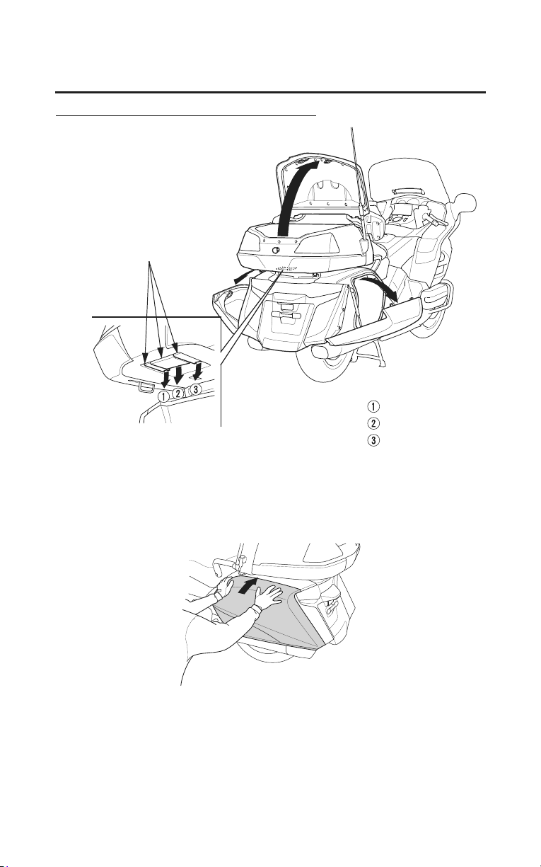
If a Saddlebag Won’t Open
REAR
rod
PUSH
plug
trunk mat
1. Open the travel trunk and turn over the trunk mat.
2. Remove the plug from the right or left access hole in the floor of the trunk.
3. Put your finger through the access hole and push the rod.
The saddlebag should open.
Before Riding
55
Cargo Compartment
Remote Transmitter
You can lock and unlock your motorcycle’s trunk and saddlebags with the
remote transmitter.
If the ignition switch is left off for more than one month, the remote transmitter
will no longer operate the remote control system. To reset the system, turn the
ignition switch ON.
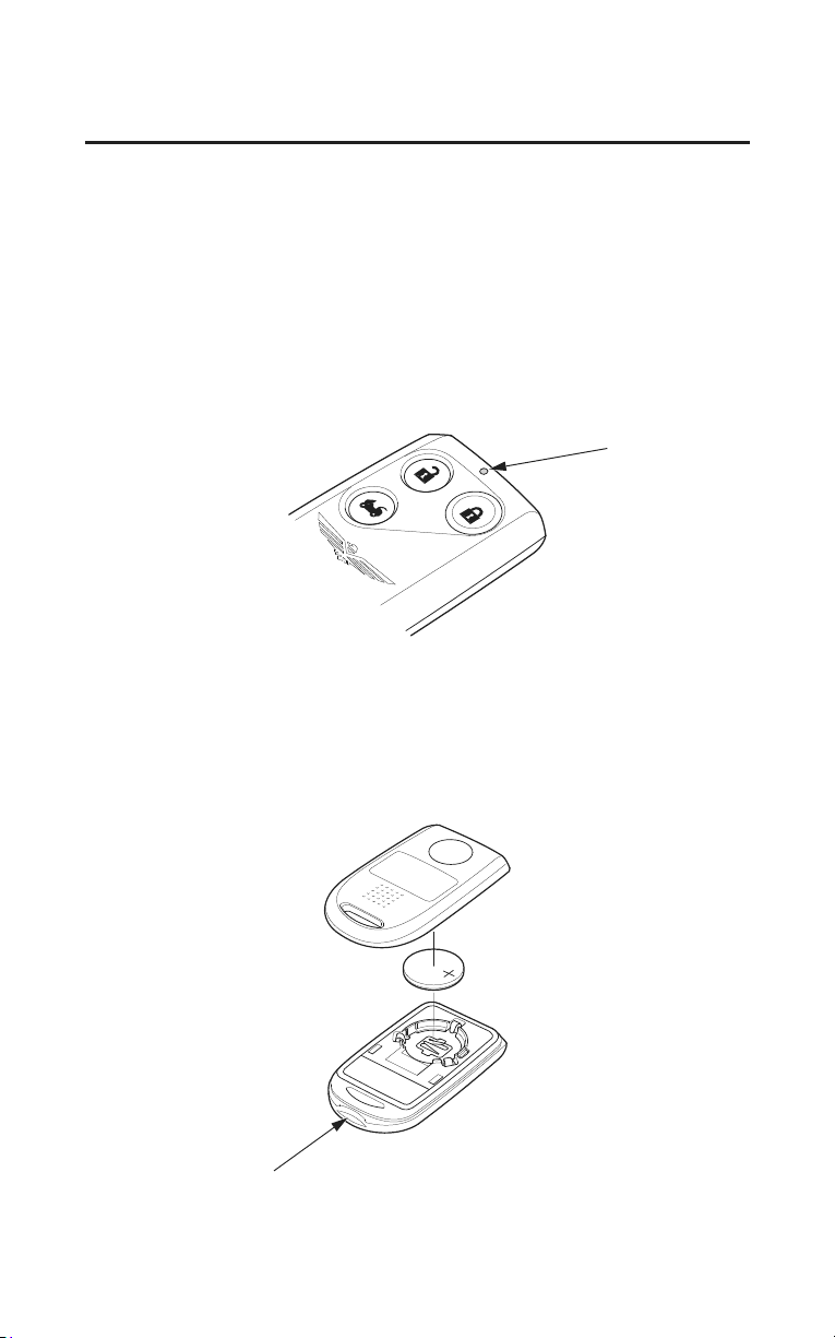
• To lock the compartments ï push the lock button.
(The front and rear turn signal lights will blink once.)
lock button
• To unlock the compartments ï push the unlock button.
(The front and rear turn signal lights will blink twice.)
unlock button
If you unlock the compartments with the transmitter, but do not open any of the
compartments within thirty seconds, the compartments automatically relock.
You cannot lock the compartments with the remote transmitter if any
compartment is not fully closed. (The front and rear turn signal lights will blink
ten times.)
56
Before Riding
Cargo Compartment
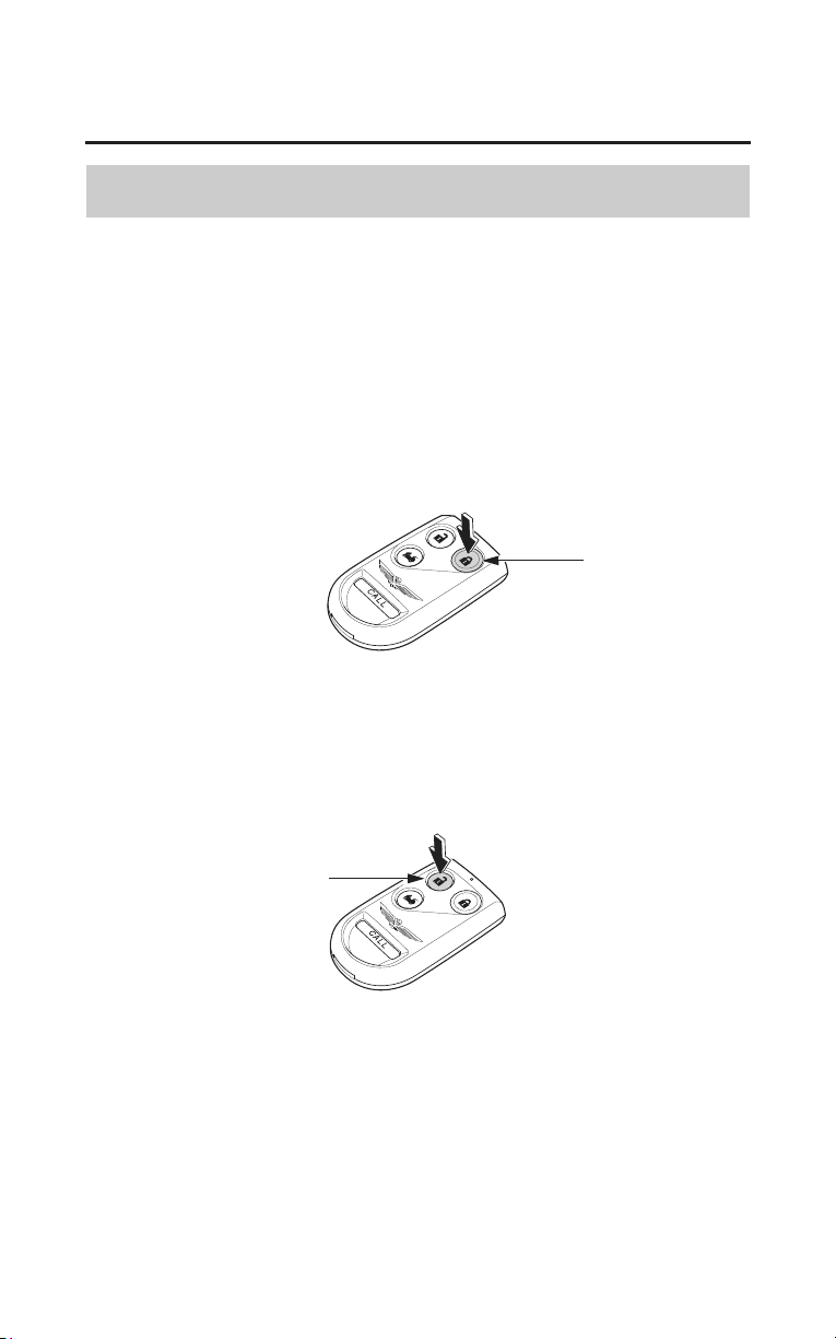
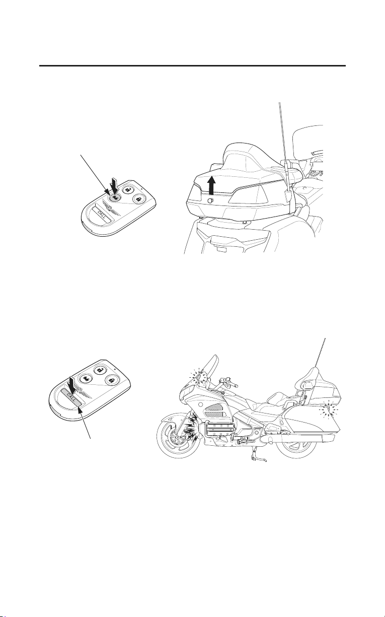
• To open the trunk, push and hold the trunk release button for approximately
one second.
trunk release button
Call Mode
The call mode is provided to let you locate your motorcycle when it is parked in
a large lot.
Push and hold the CALL button, the horn will sound and the turn signal lights
will blink two times.
CALL button
When the ignition switch is in the ON or ACC position:
• You can lock and unlock the compartments.
• The trunk release button will not operate.
• The call mode will not operate.
Before Riding
57
Cargo Compartment
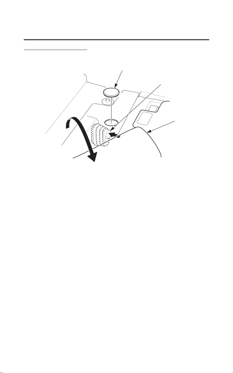
Replacing the Battery
When the remote transmitter’s battery begins to get weak, it may take several
pushes on the button to lock or unlock the compartments, and the LED will get
dim. Replace the battery as soon as possible.
Battery type: CR2025
Recycle or dispose of batteries properly, according to local regulations.
Improper battery disposal can harm the environment.
LED
1. Dismantle by inserting a coin or a flat head screwdriver covered with a
protective cloth into the slit of the transmitter.
2. Remove the old battery and note the polarity. Make sure the polarity of the
new battery is the same (+ side facing up), then insert it in the transmitter.
3. Put the two halves of the transmitter back together.
slit

58
Before Riding
Cargo Compartment
Transmitter Care
Avoid severe shock to the transmitter, such as dropping or throwing it. Also,
protect it from extreme hot or cold temperatures.
Clean the transmitter case with a soft cloth. Do not use strong cleaners or
solvents that could harm the case. Immersing the transmitter in any liquid will
harm the transmitter and cause it to not function properly.
If you lose a transmitter, you will need to have the replacement programmed to
your motorcycle’
s system by your dealer. Any other transmitters you have will
also need to be reprogrammed.
As required by the FCC (USA only):
This device complies with Part 15 of the FCC rules. Operation is subject to the
following two conditions: (1) This device may not cause harmful interference,
and (2) this device must accept any interference received, including interference
that may cause undesired operation.
Changes or modifications not expressly approved by the party responsible for
co
mpliance could void the user’s authority to operate the equipment.
This device also complies with Industry Canada Standard RSS-210.
Operation is subject to the following two conditions: (1) this device may not
cause interference, and (2) this device must accept any interference that may
cause undesired operation of the device.
Before Riding
59
Cargo Compartment
Fairing Pocket / Shelter Case
LEFT SIDE
RIGHT SIDE
lid
(Models not equipped with Airbag)
PUSH
button
fairing pocket
shelter case
lid ignition key
The fairing pocket and shelter case are for lightweight items.
Cargo should not exceed:
in fairing pocket 4.5 lb (2.0 kg)
in shelter case 6.6 lb (3.0 kg)
To open the fairing pocket, push the button.
(Models not equipped with Airbag)
To open the shelter case, insert the ignition key, turn it clockwise.
To close the fairing pocket and/or shelter case, place your hands flat on the
ed
ges of its lid and press down until it is firmly closed.
Make sure the fairing pocket and shelter case are closed before riding.
Be careful not to flood this area when washing your motorcycle.
Take care to keep gasoline, brake fluid, or other chemical solvents off the lids.
They will damage the surface of the lids.
Do not store valuables in the fairing pocket and shelter case.
60
Before Riding
Cargo Compartment
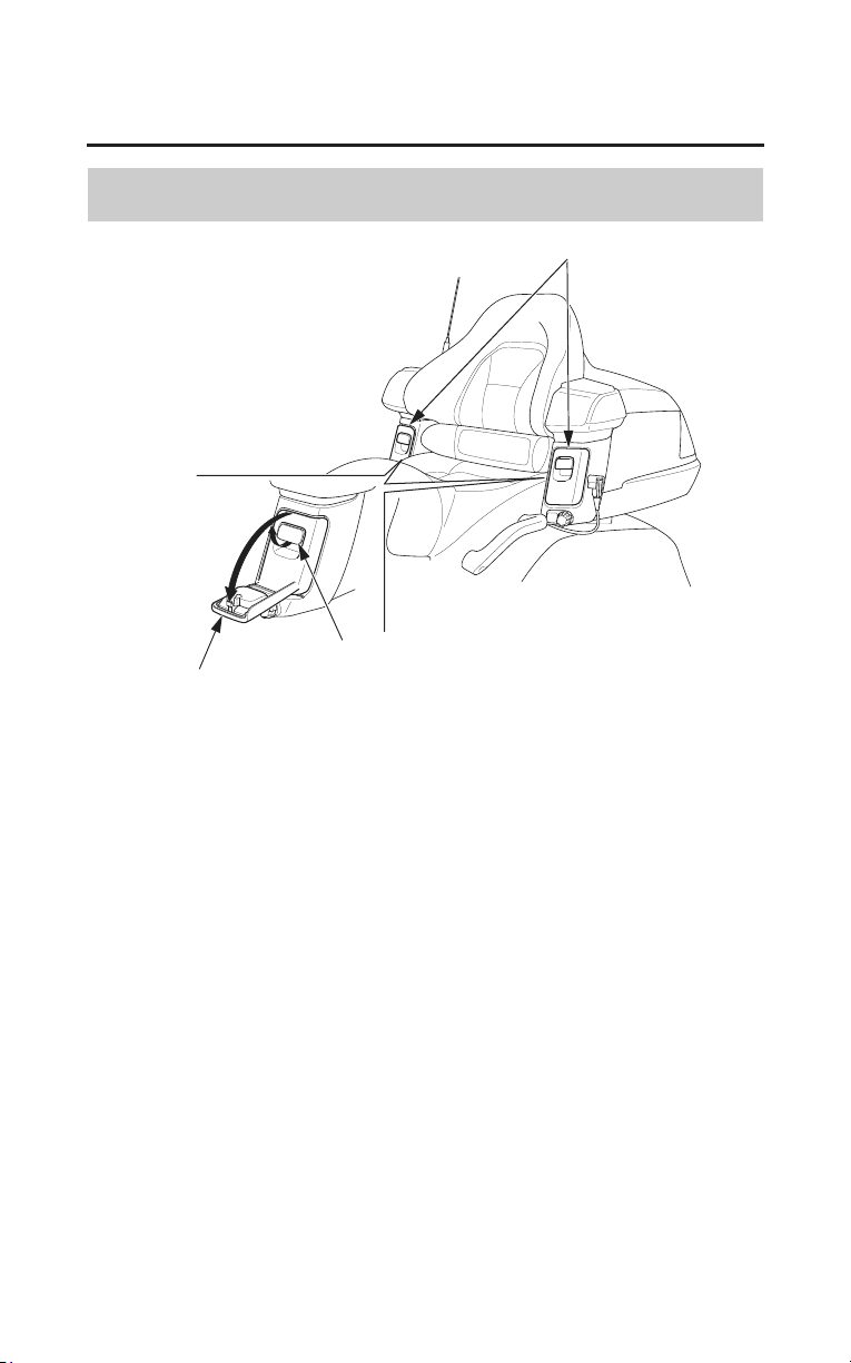
Trunk Side Pockets
lid
trunk side pockets
lever
The trunk side pockets are for soft, lightweight items.
Cargo in each trunk side pocket should not exceed:
1.0 lb (0.5 kg)
Do not put sharp or hard objects in the trunk side pockets. Such objects could
interfere with opening the lids or damage the pockets.
To open the lid, pull the lever up.
To close the lid, pull the lid up. Check that latch is secure.
Make sure the trunk side pockets are closed before riding.
Be careful not to flood this area when washing your motorcycle.

Before Riding
61
Comfort & Convenience Adjustment
Your motorcycle has many features you can adjust to suit your personal
preference and increase your comfort and convenience, and your passenger’s as
well.
We recommend that you take time to check the following items and make any
desired adjustments before each ride:
Suspension The rear suspension spring pre-load (page 192) can be
adjusted for a softer or firmer ride using an electrical
adjustment system. You may want to adjust your suspension
whenever you change your normal load.
Windscreen
Height
Your windscreen height can be adjusted slightly higher or
lower (page 62).
Ventilation
Louver
s
If you need to adjust the ventilation louvers (pages 63 ï 64),
do it before you ride.
Handgrip
Heater
The range of the handgrips heater can be adjusted higher or
lower (page 65).
Make sure the handgrip heater switch moves easily over the
full adjustment range.
Select the heat level you want before your ride (with the
engine running).
Seat Heater The range of the seat heater can be adjusted higher or lower
(page 66).
Make sure the seat heater switch moves easily over the full
adjustment range.
Select the heat level you want before your ride (with the
engin
e running).
62
Before Riding
Comfort & Convenience Adjustment
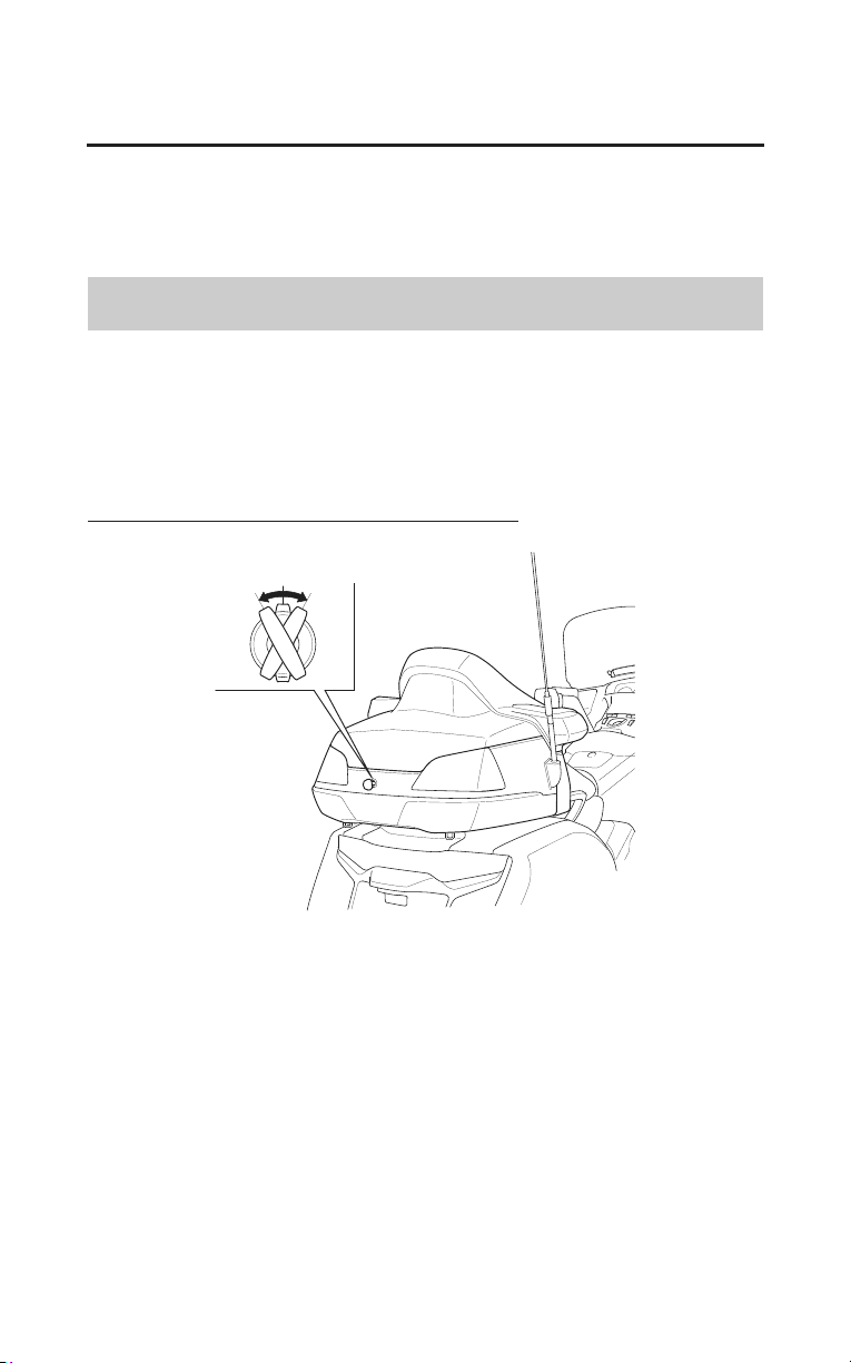
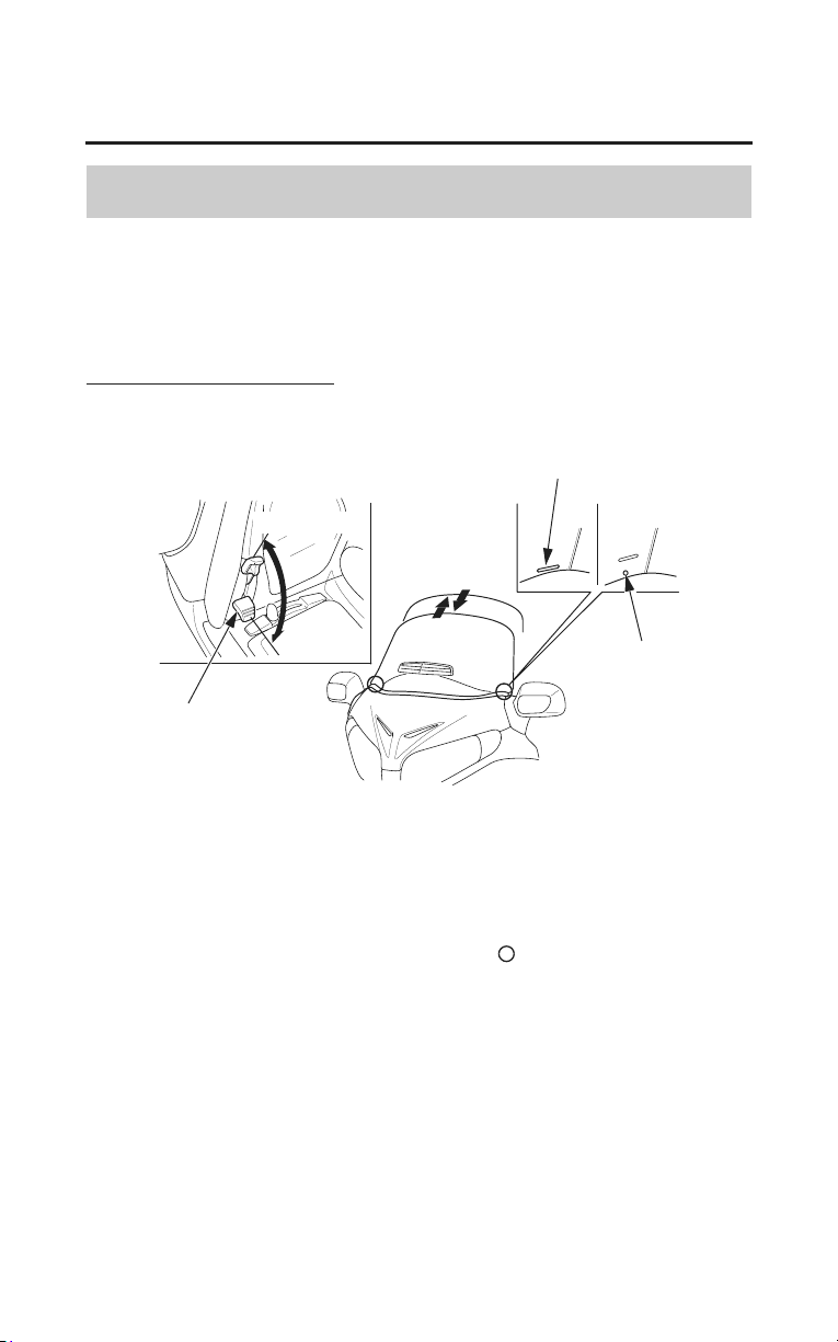
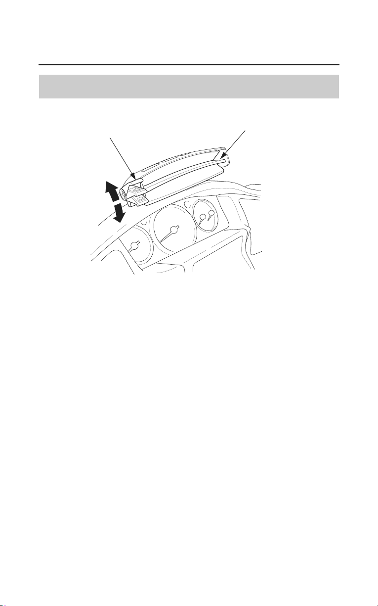
Windscreen Height Adjustment
The windscreen adjuster has 6 positions.
You can adjust your windscreen height slightly higher or lower.
If possible, we recommend you adjust your windscreen height to below eye
level for better visibility.
To Adjust Windscreen Height
FRONT
RELEASE
lever
upper edge
upper mark
SECURE
1. Pull both levers up to release the windscreen.
2. To raise:
Move the windscreen up to the desired position.
To lower:
Move the windscreen up to the upper mark (
), lower it all the way (to
reset the ratchet mechanism), then raise it to the desired position.
3. On both sides, align the mark on the windscreen with the upper edge of the
instrument panel.
4. Push the levers down to secure the windscreen.
Before Riding
63
Comfort & Convenience Adjustment
Windscreen Ventilation Louver
CLOSE
lever
windscreen ventilation louver
OPEN
You can adjust the windscreen ventilation louver with the lever to control and
direct the flow of fresh air.

64
Before Riding
Comfort & Convenience Adjustment
Foot Warmer Ventilation Louvers
lever
LEFT UPPER
LEFT SIDE RIGHT SIDE
OPEN
CLOSE
You can adjust the foot warmer ventilation louvers with the lever to control and
direct the flow of warm air.
Before Riding
65
Comfort & Convenience Adjustment
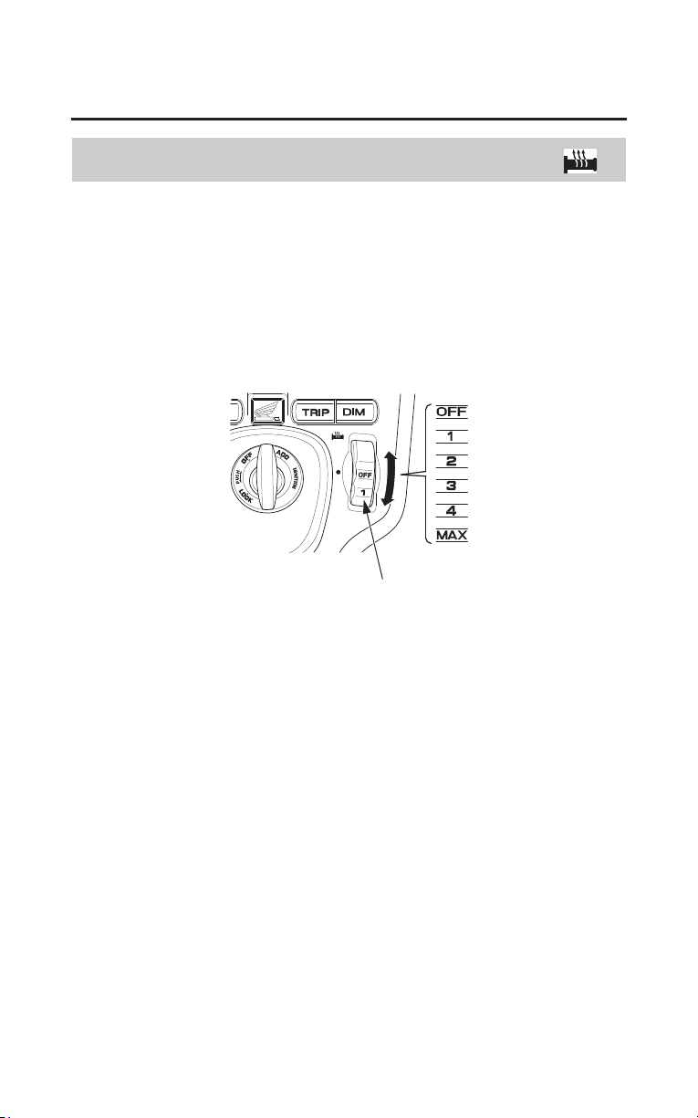
Handgrip Heater
The handgrip heater warms up the right and left handgrips of the handlebar for
comfortable riding on a cold day.
The handgrip heater switch is located on the right side of the ignition switch.
To operate, adjust the handgrip heater switch with the engine started. The
handgrip heater switch has 6 positions (OFF, 1, 2, 3, 4, MAX).
handgrip heater switch
RIGHT SIDE OF THE IGNITION SWITCH
To warm up the handgrip heaters, turn the handgrip heater switch toward the
MAX position.
To cool down the handgrip heaters, turn the handgrip heater switch toward the
OFF position.
Do not leave the handgrip heater in the high position for a long time on a warm
da
y.
Wear gloves to protect your hands from the heated grips.
Do not use the handgrip heater with the engine at idle for a long time. It may
result in a low (or dead) battery.
66
Before Riding
Comfort & Convenience Adjustment
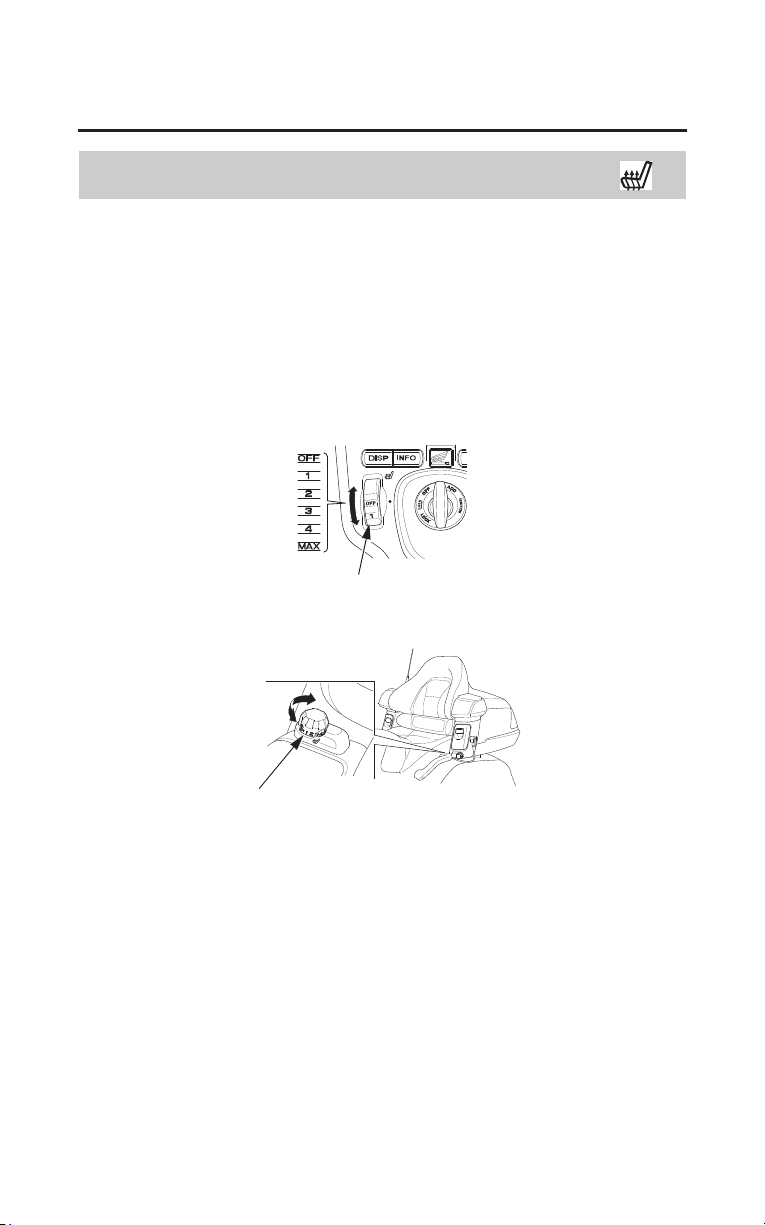
Seat Heater
The seat heater warms up the driver’s seat (and the passenger’s seat) for
comfortable riding on a cold day.
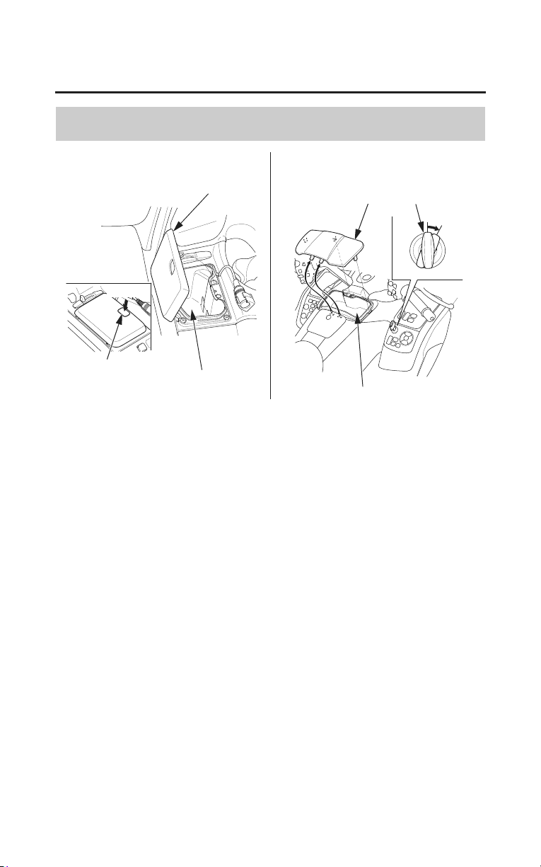
The front seat heater switch is located on the left side of the ignition switch.
The rear seat heater switch is located under the left trunk side pocket.
To operate, adjust the seat heater switch with the engine started.
The front and rear seat heater switches have 6 positions (OFF, 1, 2, 3, 4, MAX).
front seat heater switch
LEFT SIDE OF THE IGNITION SWITCH
UNDER THE LEFT TRUNK SIDE POCKET
rear seat heater switch
To warm up the seat heater, turn the seat heater switch toward the MAX
position.
To cool down the seat heater, turn the seat heater switch toward the OFF
position.
Do not leave the seat heater in the high position for a long time on a warm day.
Do not use the seat heater with the engine at idle for a long time. It may result in
a low (or dead) battery.
Do
not use the seat heater when the seat is torn, cut or damaged as you can get
burned.
Do not apply excessive stress to the seat, e.g. by securing articles to it with tie-
down straps during transportation.
Before Riding
67
Accessories
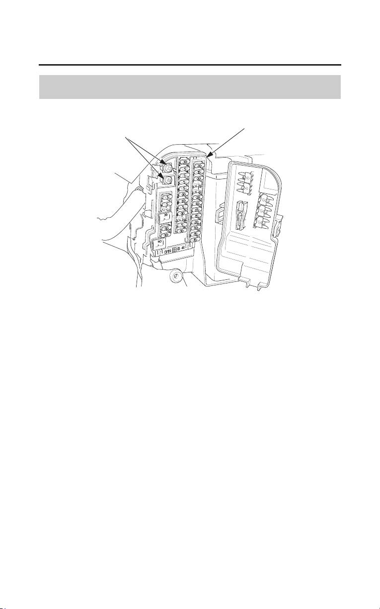
Accessory (ACC) Terminal
accessory (ACC) terminal
fuse box
For your convenience, your motorcycle is equipped with an accessory (ACC)
terminal and optional accessory socket. The terminal and socket provide 12V
DC power for electrical accessories. When both terminal and socket are being
used, the combined power rating of each accessory should be 60 watts (5 amps)
or less. Before installing any accessories, read Accessories & Modifications,
page 4.
If you install any accessories, check the battery frequently to determine the state
of charge. Higher current demands may blow a fuse or discharge the battery. For
more information, see Battery, page
209, and If a Fuse Blows, page 244.
Connect accessory electrical leads securely, and keep them insulated, away from
hot parts and sharp edges.

Basic Operation & Riding
69
Basic Operation & Riding
This section gives basic riding instructions, including how to start and stop your
engine, and how to use the throttle, clutch, and brakes. It also provides
important information on riding with a passenger or cargo, and operating your
cruise control.
To protect your new engine and enjoy optimum performance and service life,
refer
to Break-in Guidelines (page 260).
To protect the catalytic converters in your motorcycle’s exhaust system, avoid
extended idling and the use of leaded gasoline.
Safe Riding Precautions ....................................................................................70
Starting & Stopping the Engine ........................................................................ 71
Preparation .................................................................................................... 71
Starting Procedure......................................................................................... 72
Flooded Engine ............................................................................................. 72
Bank Angle Sensor Ignition Cut-off System ................................................73
How to Stop the Engine ................................................................................ 73
Shifting Gears.................................................................................................... 74
While You Are Riding ..................................................................................75
Riding in Reverse.............................................................................................. 76
Braking.............................................................................................................. 78
Combined ABS .............................................................................................80
ABS Indicator Light......................................................................................81
Tire Pressure Monitoring System (TPMS)........................................................ 83
Low Tire Pressure Indicator.......................................................................... 84
Tire Pressure Monitoring System (TPMS) Indicator....................................85
Changing a Tire with TPMS ......................................................................... 86
Parking .............................................................................................................. 87
Theft-prevention Tips....................................................................................89
Riding with a Passenger or Cargo ..................................................................... 90
Riding with Cruise Control ............................................................................... 91
Cruise Control............................................................................................... 91
To Set Cruise Control.................................................................................... 92
To Change the Set Speed .............................................................................. 92
To Cancel Cruise Control.............................................................................. 93
Riding in Bad Weather ......................................................................................94

70
Basic Operation & Riding
Safe Riding Precautions
Before riding your motorcycle for the first time, please review the Motorcycle
Safety section beginning on page 1, and the Before Riding section beginning on
page 43.
Even if you have ridden other motorcycles, take time to become familiar with
how this motorcycle works and handles. Practice in a safe area until you build
your skills and get accustomed to the motorcycle’s size and weight.
Make sure flammable materials such as dry grass or leaves do not come in
contact
with the exhaust system when riding, idling, or parking your
motorcycle.

Basic Operation & Riding
71
Starting & Stopping the Engine
Always follow the proper starting procedure described below.
For your safety, avoid starting or operating the engine in an enclosed area such
as a garage. Your motorcycle’s exhaust contains poisonous carbon monoxide
gas which can collect rapidly in an enclosed area and cause illness or death.
Your motorcycle can be started with the transmission in gear by pulling in the
clutch lever before operating the starter.
Your motorcycle is equipped with a side stand ignition cut-off system. If the
side stand is down –– the engine cannot be started unless the transmission is in
neutral. If the side stand is up –– the engine can be started in neutral, or in gear
with the clutch lever pulled in. After starting with the side stand down, the
engine will stop if the transmission is put in gear before raising the side stand.
Preparation
Before starting, insert the key, turn the ignition switch ON, and confirm the
following:
• The transmission is in neutral (neutral indicator is ON).
• The engine stop switch is set to RUN.
• The low oil pressure indicator is ON.
• The PGM-FI malfunction indicator lamp (MIL) is OFF.
• The ABS indicator light is ON (models equipped with ABS).
• The airbag indicator is OFF (models equipped with Airbag).
The low oil pressure indicator and airbag indicator (models equipped with
Airbag)
should go off a few seconds after the engine starts. If the low oil
pressure indicator lights during operation, stop the engine immediately and
check the engine oil level.
If the airbag indicator stays on or lights during operation, have your motorcycle
inspected as soon as possible by an authorized dealer (models equipped with
Airbag).

72
Basic Operation & Riding
Starting & Stopping the Engine
Starting Procedure
This motorcycle has a fuel-injected engine with an automatic fast idle. Follow
the procedure indicated below.
Any Air Temperature
• Press the start button with the throttle completely closed.
The engine will not start if the throttle is fully open (because the electronic
control module cuts off the fuel supply).
Snapping the throttle or fast idling for more than about 5 minutes at normal air
temperature may cause exhaust pipe discoloration.
Flooded Engine
If the engine fails to start after repeated attempts, it may be flooded with excess
fuel. To clear a flooded engine:
1. Leave the engine stop switch set to RUN.
2. Open the throttle fully.
3. Press the start button for 5 seconds.
4. Follow the normal starting procedure.
5. If the engine starts, open the throttle slightly if idling is unstable.
If the engine does not start, wait 10 seconds, then follow steps 1 – 4 again.
If the engine still won’t start, refer to If Your Engine Quits or Won’t Start, page
227.

Basic Operation & Riding
73
Starting & Stopping the Engine
Bank Angle Sensor Ignition Cut-off System
Your motorcycle’s banking (lean angle) sensor system is designed to
automatically stop the engine and fuel pump if the motorcycle is overturned.
Before restarting the engine, you must turn the ignition switch to the OFF
position and then back to ON. The engine will not restart until you perform this
procedure.
How to Stop the Engine
Normal Engine Stop
To stop the engine, shift into neutral and turn the ignition switch OFF.
The engine stop switch should normally remain in the RUN position even when
the engine is OFF.
If your motorcycle is stopped with the ignition switch ON and the engine stop
switch OFF, the headlight and taillight will remain on, resulting in battery
discharge.
Emergency Engine Stop
To stop the engine in an emergency, use the engine stop switch. To operate, turn
the switch to the OFF position.

74
Basic Operation & Riding
Shifting Gears
Your motorcycle has five forward gears in a one-down, four-up shift pattern
which is coordinated with a hydraulically actuated clutch system.
Learning when to shift gears comes with experience. Keep the following tips in
mind:
• As a general rule, shift while moving in a straight line.
• Close the throttle and pull the clutch lever in completely before shifting. Improper
shifting may damage the engine, transmission, and drive train.
• Learn to recognize the engagement point as you release the clutch lever. It is
at this point the transmission of power to the rear wheel resumes.
• Upshift to a higher gear or reduce throttle before engine rpm (speed) gets too
high. Learn the relationship between engine sound and the normal shifting
points.
• Downshift to a lower gear before you feel the engine laboring (lugging) at
low rpm.
• Avoid downshifting to help slow your motorcycle when engine rpm is near its
allowable maximum (near the tachometer red zone). In this situation, the rev
limiter in the engine ignition control module may not prevent excessive
engine speed which could damage the engine.
• To prevent transmission damage, do not coast or tow the motorcycle for long
distances with the engine off.

Basic Operation & Riding
75
Shifting Gears
Recommended Shift Points
Ride in the highest gear that lets the engine run and accelerate smoothly. This
will give you good fuel economy and effective emissions control. When
changing gears under normal conditions, use these recommended shift points:
Shifting Up:
From 1st to 2nd: 12 mph (20 km/h)
From 2nd to 3rd: 19 mph (30 km/h)
From 3rd to 4th: 25 mph (40 km/h)
From 4th to OD: 31 mph (50 km/h)
Shifting Down:
From OD to 4th: 22 mph (35 km/h)
From 4th to 3rd: 16 mph (25 km/h)
Pull the clutch lever in when speed drops below 12 mph (20 km/h), when engine
roughne
ss is evident, or when engine stalling is imminent; and shift down to 1st
gear for acceleration.
While You Are Riding
While you are riding, occasionally check your gauges and indicators.
Continuing to ride with the low oil pressure indicator (red) on or the coolant
temperature gauge needle at the H (hot) mark can cause serious engine damage.
Also keep an eye on the fuel gauge and the low fuel indicator.
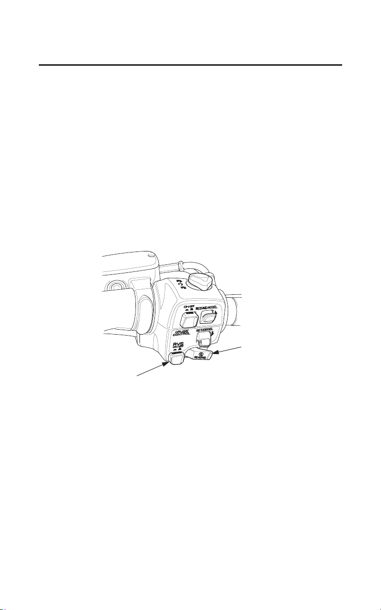
76
Basic Operation & Riding
Riding in Reverse
Your motorcycle’s reverse system allows you to back out of a parking position
at slow speed.
Make sure there are no obstacles or people in the area. Avoid steep or uneven
surfaces. Carrying a passenger while reversing is not recommended because it
makes balance and control more difficult to maintain.
1. Sit astride the motorcycle, in your normal riding position, with both feet on
the ground.
2. Make sure the transmission is in neutral (neutral indicator is ON) and the side
stand is up.
3. Start the engine. (Make sure the RVS switch is OFF.)
4. Push the RVS switch to ON, then make sure the reverse system indicator
comes on.
RIGHT HANDLEBAR
reverse (RVS) switch
start/reverse button
5. When you are ready to back up, push the start/reverse button and hold it in.
The motorcycle will move in reverse as long as you hold the button in.
To prevent battery discharge, do not push the start/reverse button more than a
minute.
6. Guide the motorcycle backward cautiously, using your legs to maintain
balance.
Use extreme care to maintain balance while reversing on loose surfaces
(sand, dirt, gravel) or grease-covered pavement.

Basic Operation & Riding
77
Riding in Reverse
7. Release the start/reverse button, and the motorcycle will stop.
8. After your motorcycle is stopped, push the RVS switch to OFF. Make sure
the reverse gear indicator goes off and the neutral indicator comes on.
To avoid damaging the reverse system, do not engage or disengage reverse when
the motorcycle is moving.
If the reverse switch is in the ON position with the engine off, the engine cannot
be started.
Reverse System Overload
The reverse system is designed to move the motorcycle at a constant slow
speed.
If the motorcycle begins moving slower or faster than this speed, because of
obstacles or a steep pavement angle, the system will shut off and the reverse
system indicator will turn OFF.
To resume reverse operation or normal forward operation, push the RVS switch
to the OFF position and carefully roll the motorcycle to a more level,
unobstructed surface, then start again.

78
Basic Operation & Riding
Braking
Your motorcycle is equipped with Dual CBS (Linked Braking System).
Operating the front brake lever applies the front brake and a portion of the rear
brake. Operating the rear brake pedal applies the rear brake and a portion of the
front brake. For full braking effectiveness, use both the lever and pedal
simultaneously, as you would with a conventional motorcycle braking system.
To slow or stop, apply the brake lever and brake pedal smoothly, while
downshifting to match your speed.
Gradually increase braking as you feel the brakes slowing your speed. The
increase in engine compression from downshifting will help slow your
motorcycle.
To prevent stalling the engine, pull the clutch lever in before coming to a
complete stop. For support, put your left foot down first, then your right foot
when you have finished braking.
When possible, reduce your speed or complete braking before entering a turn.
Avoid braking or closing the throttle quickly while turning. Either action may
cause one or both wheels to slip and reduce your control of your motorcycle.
Your ability to brake in a turn and to brake hard in an emergency situation are
important riding skills.
We suggest attending a Motorcycle Safety Foundation
experienced rider training course (page 46) to retain these skills.
When riding in wet or rainy conditions, or on loose surfaces, the ability to
maneuver and stop will be reduced. All of your actions should be smooth under
these conditions. Rapid acceleration, braking or turning may cause loss of
control.
For your safety, exercise extreme caution when braking, accelerating or turning.
When descending a long, steep grade, use engine compression braking by
downshifting,
with intermittent use of both brakes. Continuous brake
application can overheat the brakes and reduce their effectiveness.

Basic Operation & Riding
79
Braking
Riding with your foot resting on the brake pedal or your hand on the brake lever
may actuate the brake light, giving a false indication to other drivers. It may also
overheat the brakes, reducing effectiveness.
(Models not equipped with ABS)
As with a conventional motorcycle braking system, excessively hard application
of
the brake controls may cause wheel lock, reducing control of the motorcycle.
Applying the brakes too hard may cause the wheels to lock and slide, reducing
control of your motorcycle. If this happens, release the brake controls, steer
straight ahead until you regain control, then reapply the brakes more gently.

80
Basic Operation & Riding
Braking
Combined ABS
(Models equipped with ABS)
This model is also equipped with an Anti-lock Brake System (ABS) designed to
help prevent wheel lock up during hard braking on uneven or other poor
surfaces while running straight. Although the wheel may not lock up if you are
braking too hard in a turn the motorcycle can still lose traction, causing a loss of
control.
In some situations, a motorcycle with ABS may require a longer stopping
distance to stop on loose or uneven surfaces than an equivalent motorcycle
without ABS.
ABS cannot make up for road conditions, bad judgment, or improper operation
of th
e brakes. It is still your responsibility to ride at reasonable speeds for
weather, road surface, and traffic conditions, and to leave a margin of safety.
ABS is self-checking and is always on.
ABS may also be activated by braking while riding over a sharp drop or rise in
the road level.
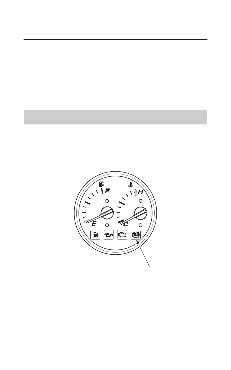
Basic Operation & Riding
81
Braking
It is important to follow the tire recommendations (see page 207). The ABS
computer works by comparing wheel speed.
Non-recommended tires can affect wheel speed and may confuse the ABS
computer.
ABS does not function at very low speeds (approximately 5 mph (8 km/h) or
below).
ABS does not function if the battery is discharged.
ABS Indicator Light
(Models equipped with ABS)
Normally, this light comes on when the ignition is turned ON and goes off after
starting to ride. If there is an ABS problem, the indicator light comes on and
remains on or blinks. The ABS system does not operate when the ABS indicator
light is on or blinking.
ABS indicator light

82
Basic Operation & Riding
Braking
If the ABS indicator light blinks while riding, stop the motorcycle in a safe
place and turn off the engine. Turn the ignition ON again. The light should come
on, and then go off after starting to ride. If it does not go off or if it blinks again,
ABS is not functioning.
However, Dual CBS (Linked Braking System) will still provide normal
stopping ability, but you should have the ABS system checked by your dealer as
soon as possible.
The ABS indicator may blink if you place the motorcycle on its center stand and
turn the rear wheel. This
is normal. Turn the ignition OFF to stop the blinking.
An amber LED is used for the ABS indicator light. Be sure that the LED lights
when the ignition is ON. If the LED fails to light, see your dealer.

Basic Operation & Riding
83
Tire Pressure Monitoring System (TPMS)
Your motorcycle is equipped with a tire pressure monitoring system (TPMS)
that turns on every time you start the engine and it monitors the pressure in your
tires while riding.
Each tire has its own pressure sensor. If the air pressure of a tire becomes
significantly low while riding, the sensor in that tire sends a signal that causes
the low tire pressure indicator to turn on.
As required by the FCC (USA only):
This device complies with
Part 15 of the FCC rules. Operation is subject to the
following two conditions: (1) This device may not cause harmful interference,
and (2) this device must accept any interference received, including interference
that may cause undesired operation.
Changes or modifications not expressly approved by the party responsible for
compliance could void the user’s authority to operate the equipment.
This device also complies with Industry Canada Standard RSS-210.
Operation is subject to the following two conditions: (1) this device may not
cause interference, and (2) this device must accept any interference that may
cause undesired operation of the device.

84
Basic Operation & Riding
Tire Pressure Monitoring System (TPMS)
Low Tire Pressure Indicator
If the low tire pressure indicator flashes, check your tires as soon as possible.
If the low tire pressure indicator lights constantly, one or more of your tires is
significantly underinflated. You should stop and check your tires as soon as
possible. For more information on temporary repair, see If You Have a Flat Tire
on page 230.
Check the air pressure when the tires are cold. This means the motorcycle has
been parked for at least 3 hours. Add or release air, if needed, to match the
recommended cold tire pressures on page 202.
When the low tire pressure indicator flashes or lights, but you continue to ride,
the low tire pressure indicator will go off in some cases. It is still necessary to
check the air pressures of both tires after the tires cool. Air in the tires is
expanded with heat.
If the low tire pressure indicator does not turn off after inflating the tires to the
specified values, have your dealer to check the system as soon as possible.
Riding on a underinflated tire causes the tire to overheat and can lead to tire
failure.
Under-inflation also reduces fuel efficiency and tire tread life, and may affect
the motorcycle’s handling and stopping ability.
low tire pressure indicator
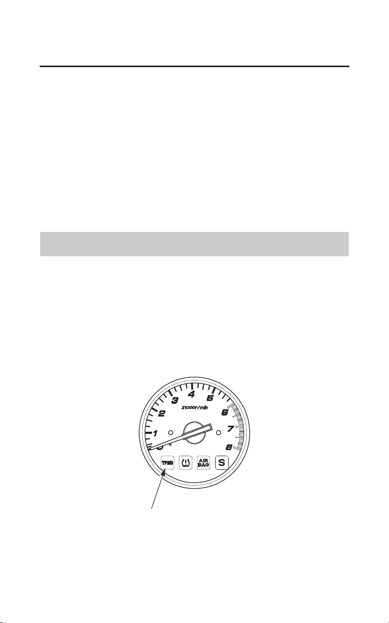
Basic Operation & Riding
85
Tire Pressure Monitoring System (TPMS)
Because tire pressure varies by temperature and other conditions, the low tire
pressure indicator may turn on unexpectedly.
Please note that the TPMS is not a substitute for proper tire maintenance, and it
is the rider’s responsibility to maintain correct tire pressure, even if under-
inflation has not reached the level of turning on the low tire pressure indicator.
For example, if you check and fill your tires in a warm area, then ride in
extremely cold weather, the tire pressure will be lower than measured and could
be underinflated and cause the low tire pressure indicator to turn on. Or, if you
check and adjust your tire pressure in cooler conditions, and ride into extremely
hot conditions, the tire may become overinflated. However, the low tire pressure
indicator will not turn on if the tires are overinflated.
Tire Pressure Monitoring System (TPMS) Indicator
The tire pressure monitoring system (TPMS) indicator comes on and stays on if
there is a problem with the tire pressure monitoring system.
If this happens, the system will shut off and no longer monitor tire pressure.
Have the system checked by your dealer as soon as possible.
Also the TPMS indicator may light for the following reasons:
• Interference of other electronic devices by using the same radio frequency.
• Using replacement wheels not equipped with tire pressure sensors.
tire pressure monitoring system (TPMS) indicator
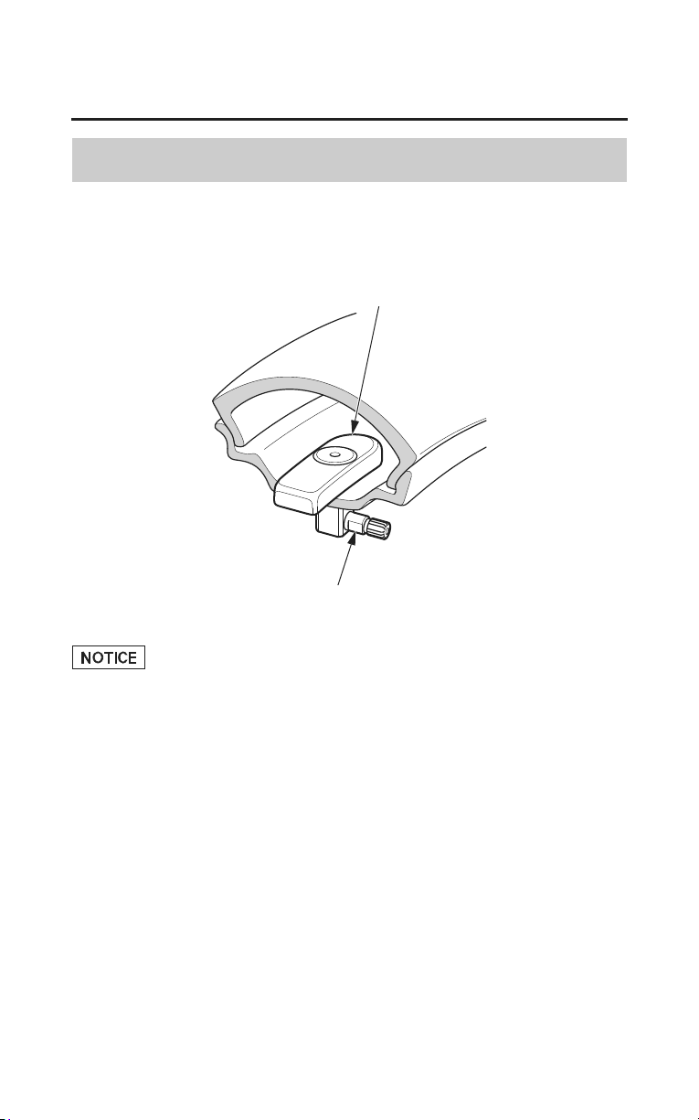
86
Basic Operation & Riding
Tire Pressure Monitoring System (TPMS)
Changing a Tire with TPMS
Each wheel is equipped with a tire pressure sensor mounted inside the tire
behind the valve stem. You must use TPMS specific wheels. Always have your
tires serviced by your dealer.
tire pressure sensor
valve stem
Using a puncture-repairing agent can damage the TPMS sensors, causing the
TPMS indicator to turn on. Have you motorcycle checked by your dealer as
soon as possible.
Use caution to not damage the TPMS sensor if an internal plug patch must be
used to repair the tire. If you have a tire professionally repaired at a non-Honda
facility, we recommend that you have the work checked by your dealer. TPMS
wheels require special handling when changing the tire. Failure to follow the
proper tire replacement procedure can result in damage to the TPMS sensor.
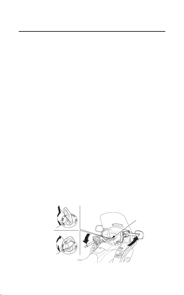
Basic Operation & Riding
87
Parking
1. Look for a level parking area. If you can’t park on a paved surface, make sure
the ground surface is firm.
If you must park on a hill, leave the transmission in gear and position the rear
tire against the curb at a 45 degree angle.
Make sure flammable materials such as dry grass or leaves do not come in
contact with the exhaust system when parking your motorcycle. Refer to
Catalytic Converters, page 267.
2. Use the side or center stand to support the motorcycle while parked.
• To lower the side stand, use your foot to guide it down. Remember that
lowering the side stand with the transmission in gear will stop the engine,
even if the clutch lever is pulled in. That is a function of the side stand
ignition cut-off system.
• Check that the side stand is down all the way. The side stand indicator only
indicates that the side stand
ignition cut-off system (page 71) is activated.
• To lower the center stand, stand on the left side of the motorcycle. Hold the
passenger handgrip attached to the seat. Press down on the tip of the stand
with your right foot and, simultaneously, pull up and back on the passenger
handgrip.
3. Use the steering lock, which locks the handlebar in place. Turn the handlebar
all the way to the left or right. Push in on the ignition key and turn it to
LOCK.
Remove the key.
(To unlock the steering lock, insert and push the key in and turn it to the right
to the OFF position.
)
TO LOCK
TO UNLOCK
PUSH IN
TURN TO LOCK
TURN TO OFF
PUSH IN
ignition key
(cont’d)
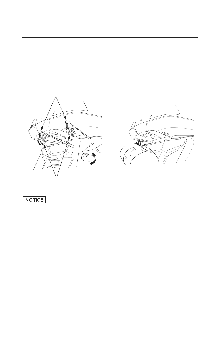
88
Basic Operation & Riding
Parking
4. Use the helmet holder(s) to secure your helmet(s) with your motorcycle:
Open the travel trunk (page 52).
Turn the knob in the trunk to unlock the helmet holders.
Hang your helmet(s), using the D-ring on the helmet strap.
Push the holder in to lock it.
knobs
helmet holders
OPEN
LOCK
Riding with a helmet attached to the helmet holder can cause damage to the
helmet, or damage to the paint or finish of your motorcycle.

Basic Operation & Riding
89
Parking
Theft-prevention Tips
• Park your motorcycle in a locked garage whenever possible. If a garage isn’t
available, park in a concealed area or in a well-lit area with enough pedestrian
traffic to discourage a thief.
• Always take the ignition key with you.
• Always use the steering lock (page 87), even if you’re parking for just a
minute or two. A thief can easily push an unlocked motorcycle to a waiting
truc
k.
• In addition to the steering lock, use a good quality anti-theft device made
specifically to lock a motorcycle to a secure object.
• If you decide to use an anti-theft device, select one of good quality and be
sure to follow the manufacturer’s instructions.
• Keep your owner’s manual, current registration, and insurance information
with your motorcycle. This will make it easier for the authorities to find you
if your motorcycle is stolen and recovered.

90
Basic Operation & Riding
Riding with a Passenger or Cargo
Your motorcycle is designed to carry you and one passenger. Whenever you add
a passenger or cargo, you must be careful not to exceed the total load limits for
this vehicle (Load Limits, page 50). Make sure your cargo is properly secured
(Loading Guidelines, page 51).
Also consider adjusting the suspension (page 192) for the extra load.
Be aware that carrying a passenger or heavy cargo can affect acceleration,
braking, and handling.
Before riding with a passenger, make sure your passenger is wearing the proper
protec
tive apparel (page 44).
Tell your passenger to hold the passenger handgrip, lean with you in the turns,
and keep their feet on the passenger footrests at all times, even when the
motorcycle is stopped at a traffic light.

Basic Operation & Riding
91
Riding with Cruise Control
Cruise Control
The cruise control system allows you to maintain a steady speed between
30 ï 100 mph (48 ï 161 km/h). When cruise control is on, your speed will still
vary slightly, particularly going up and down hills.
Cruise control is intended for use only on straight, uncongested highways. Do
not use cruise control on city streets, winding roads, during bad weather, or at
any other time when you need total control of the throttle.
Improper use of the cruise
control can lead to a crash.
Use the cruise control only when
traveling on open highways in
good weather.
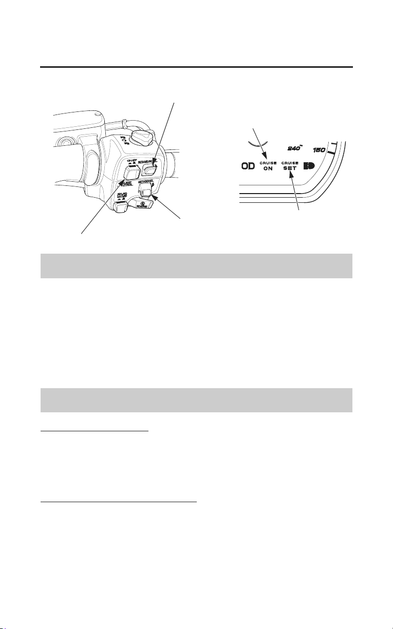
92
Basic Operation & Riding
Riding with Cruise Control
RIGHT HANDLEBAR
RESUME/ACCEL switch
SET/DECEL switch
CRUISE CONTROL master switch
CRUISE SET
indicator
CRUISE ON
indicator
To Set Cruise Control
1. Make sure you are in 4th gear or OD (5th gear), and that your speed is
between 30 and 100 mph (48 and 161 km/h).
Any speed above 100 mph (161 km/h) will be memorized as 100 mph (161
km/h).
2. Push the CRUISE CONTROL master switch. (The CRUISE ON indicator
will come on.)
3. Accelerate to the desired speed.
4. Push the SET/DECEL switch. (The CRUISE SET indicator will come on.)
To Change the Set Speed
To Fine Tune the Set Speed
• To increase the set speed ï tap the RESUME/ACCEL switch.
• To decrease the set speed ï tap the SET/DECEL switch.
Each quick tap (brief push and release) on either switch will change your
speed by approximately 1 mph (1.6 km/h).
To Automatically Change the Set Speed
• To increase the set speed ï hold the RESUME/ACCEL switch in. The system
will accelerate your motorcycle automatically. When you reach the desired
speed, release the switch.
• To decrease speed ï hold the SEL/DECEL switch in. The system will
automatically slow your motorcycle. When you reach the desired speed,
release the switch.

Basic Operation & Riding
93
Riding with Cruise Control
To Manually Increase the Set Speed
1. Use the throttle to accelerate until you reach the desired speed.
2. Push and release the SET/DECEL switch.
To Manually Increase Vehicle Speed
1. Use the throttle in the normal manner to accelerate.
2. To return to the set speed, close the throttle and coast without applying the
brakes. The cruise system will maintain the speed you previously set.
To Cancel Cruise Control
To Disengage the System
1. Push the CRUISE CONTROL master switch until the CRUISE ON indicator
goes off. (The set speed will be erased from memory.)
To Temporarily Disengage the System
1. Pull the brake lever or clutch lever slightly, or step on the brake pedal slightly,
or close the throttle. (The set speed will remain in memory.)
2. To resume cruise control:
• If you are still over 30 mph (48 km/h) ï push the RESUME/ACCEL
switch.
• If you are under 30 mph (48 km/h) ï use the throttle to increase road speed
above 30 mph (48 km/h) and then push the RESUME/ACCEL switch.

94
Basic Operation & Riding
Riding in Bad Weather
If you decide to ride your motorcycle in the rain, fog, or other bad-weather
conditions, ride carefully. Wet road surfaces reduce traction, especially in turns,
and increase stopping distances when you brake.
If the weather turns bad while you are riding, take extra care and do not use
cruise control.
When riding in the rain, we recommend you adjust your windscreen height
below eye level, if possible, for better visibility (page 62).
Avoid using any kind of water-dispersing product on the windscreen. It will
damage the plastic.

Audio Systems
95
Audio Systems
This section gives information about the controls and displays that make up
your audio system. All essential controls are within easy reach.
As required by the FCC (USA only):
This device complies with Part 15 of the FCC Rules for Radio Receiver.
Operation is subject to the condition that this device may not cause harmful
interference. Any unauthorized changes or modifications to this equipment
would void the user’s authority to operate this device.
Trade Name: Panasonic
Model No.: For USA CR-LH01E0AJ
For Canada CR-LH01E1AJ
Responsible Party: Panasonic Corporation of North America
One Panasonic Way, Secaucus, NJ 07094
Audio Systems ..................................................................................................97
MOD
E Knob/Button Function...................................................................... 97
VOLUME Knob/Button Function ................................................................98
Display Locations ......................................................................................... 99
Controls Locations ...................................................................................... 101
Audio Component Locations ......................................................................103
System Control............................................................................................ 104
Switch Output ............................................................................................. 105
VOLUME Control ......................................................................................106
Tone Control ............................................................................................... 107
Fader Control .............................................................................................. 109
SRS ............................................................................................................. 110
Beep Set ...................................................................................................... 111
Auto Volume Control (AVC) ...................................................................... 112
Muting......................................................................................................... 113
AM/FM Radio................................................................................................. 114
Radio Antenna ............................................................................................ 114
Select Band ................................................................................................. 115
Select Station .............................................................................................. 116
Preset Stations............................................................................................. 117
Auto Select.................................................................................................. 118
(cont’d)

96
Audio Systems
Audio Systems
XM
®
Radio (USA only).................................................................................. 119
Receiving XM
®
Radio Service ................................................................... 119
Operating the XM
®
Radio...........................................................................122
XM
®
Radio Display Messages.................................................................... 122
Select Channel ............................................................................................ 123
Preset Channel ............................................................................................124
Weather Information ....................................................................................... 125
Weather Band (WB)....................................................................................125
Auxiliary Function .......................................................................................... 127
Auxiliary (AUX) Input ............................................................................... 127
Input Jack Setup..........................................................................................128
iPod
®
/USB Flash Drive...................................................................................130
Playable iPod
®
/USB Flash Drive................................................................130
Playable music files ....................................................................................132
USB Cable .................................................................................................. 134
Playing an iPod
®
......................................................................................... 135
Playing a USB Flash Drive ......................................................................... 140
USB Error Messages................................................................................... 143
Intercom (I-COM) System .............................................................................. 144
System Control............................................................................................ 144
VOLUME Control ......................................................................................145
Intercom Muting ......................................................................................... 146
Navigation System .......................................................................................... 147
System Control............................................................................................ 147
Switch Output ............................................................................................. 147
Navi Volume Control .................................................................................. 148
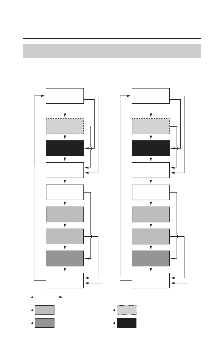
Audio Systems
97
Audio Systems
MODE Knob/Button Function
INITIAL
DISPLAY
‘‘USB MENU’’
‘‘iPod MENU’’
‘‘BASS’’
‘‘TREBLE’’
‘‘FADER’’
‘‘SRS CS Auto’’
‘‘SRS
Headphone’’
‘‘BEEP’’
Push the MODE Knob/Button
When the speaker
is used
When the headset
is used
When USB flash drive
is used
When iPod
®
is used
When
audio is
OFF
(Models not equipped with
Navigation System)
(Models equipped with
Navigation System)
When audio is ONWhen audio is ON
When
audio is
OFF
INITIAL
DISPLAY
‘‘USB Menu
Selection’’
‘‘iPod Menu
Selection’’
‘‘Bass’’
‘‘Treble’’
‘‘Fader’’
‘‘SRS CS Auto’’
‘‘SRS
Headphone’’
‘‘Beep’’
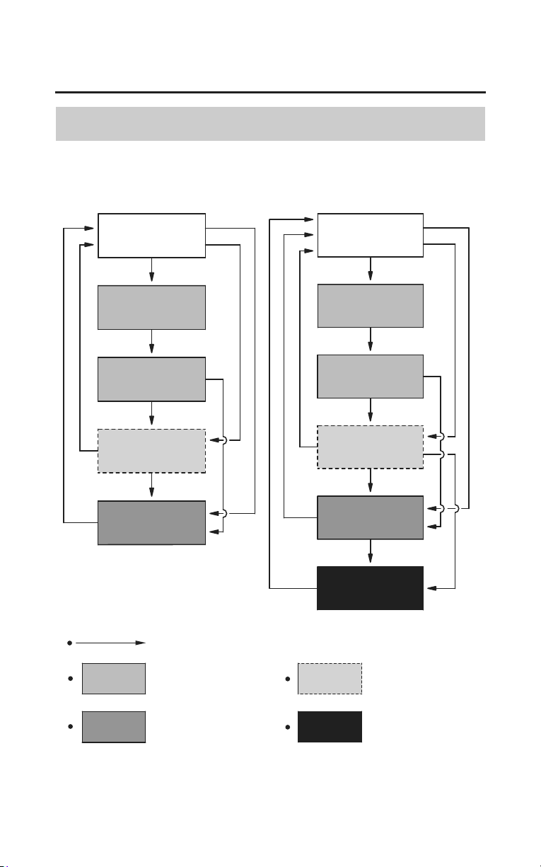
98
Audio Systems
Audio Systems
VOLUME Knob/Button Function
‘‘AUDIO’’
‘‘INTERCOM
MUTE’’
‘‘INTERCOM VOL’’
Push the VOLUME Knob/Button
When INT. COM
is ON
When the headset
is used
When the
speaker is used
‘‘NAVI VOL’’
‘‘Intercom Mute’’
‘‘Audio’’
‘‘Intercom’’
‘‘AUTO VOL SPK’’
‘‘Auto VOL SPK’’
‘‘AUTO VOL HS’’
‘‘Auto VOL HS’’
Vehicle equipped
with Navigation
System
(Models not equipped with
Navigation System)
(Models equipped with
Navigation System)
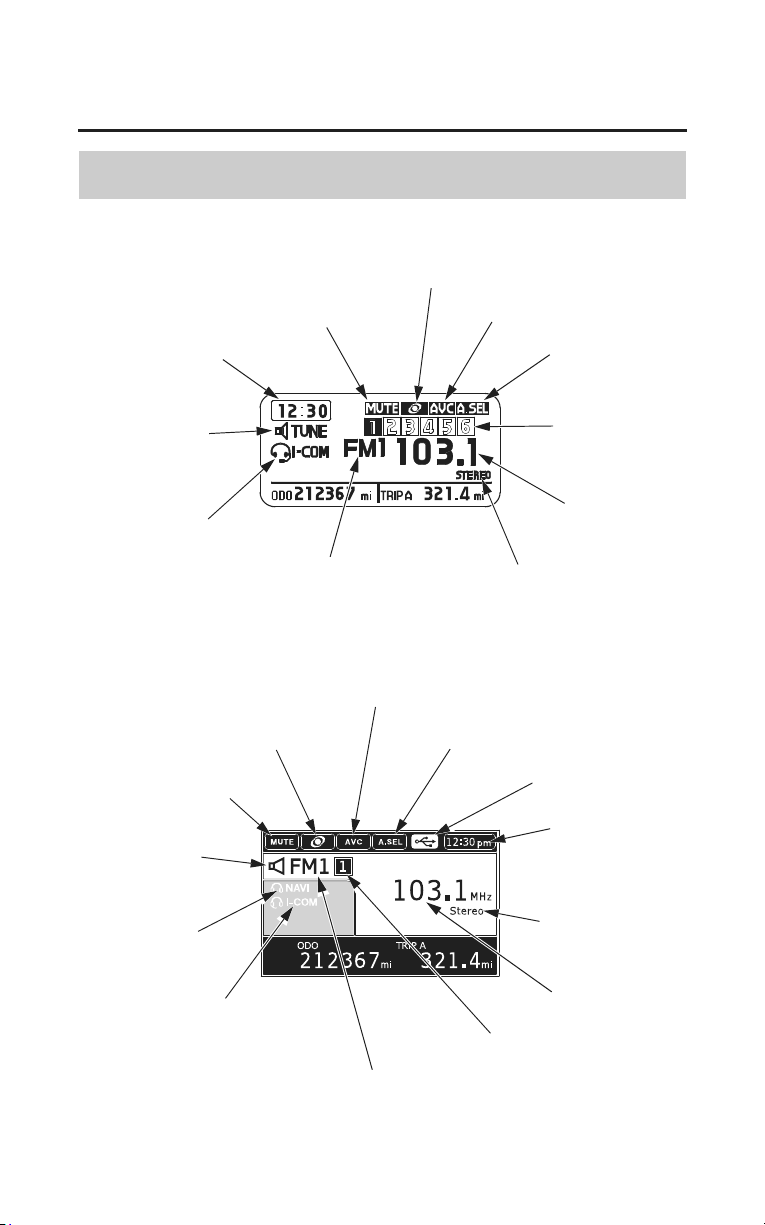
Audio Systems
99
Audio Systems
Display Locations
audio mode
indicator
clock display
(Models not equipped with Navigation System)
(Models equipped with Navigation System)
audio mode
indicator
intercom mode
indicator
radio band
stereo indicator
radio station
radio preset
channel
auto select
indicator
auto volume indicator
SRS indicator
mute indicator
radio band
radio preset channel
radio station
stereo
indicator
clock display
USB indicator
auto select indicator
auto volume indicator
SRS indicator
mute indicator
NAVI mode
indicator
intercom mode
indicator
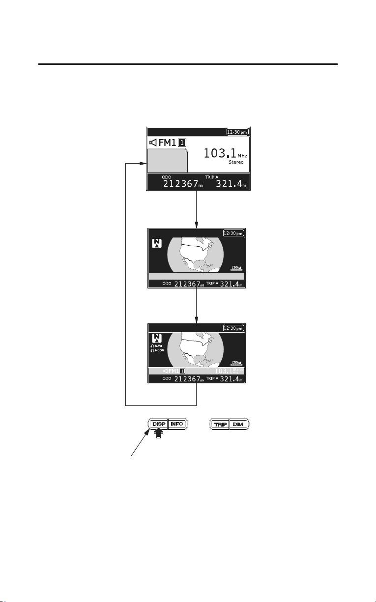
100
Audio Systems
Audio Systems
(Models equipped with Navigation System)
Press the DISP button to toggle between the Multi Information Display (time,
audio, odo and trip), a Navi full screen map with the time, and a split screen
with the Multi information condensed in a bar below the map.
DISP button
If you are not in the Navigation System when you turn the ignition switch OFF,
you will see the audio display when you turn the ignition switch ON again. If
you were in the system, you will see the system disclaimer with ENT
highlighted.
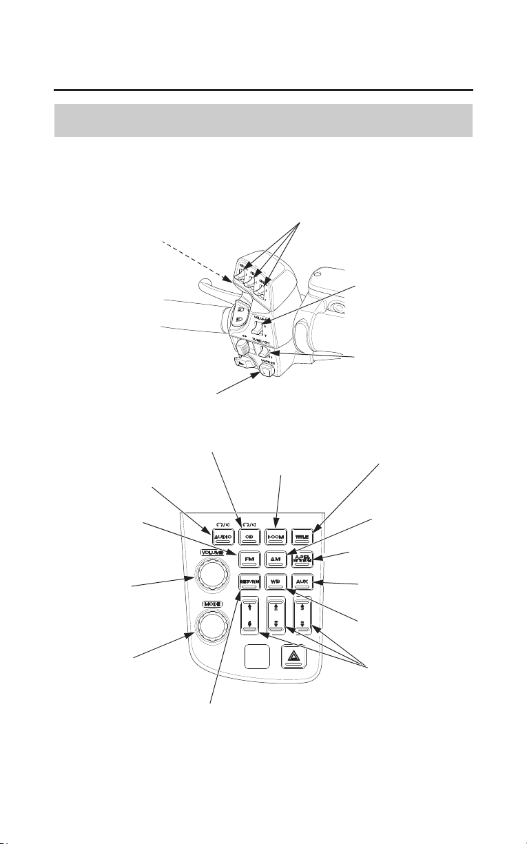
Audio Systems
101
Audio Systems
Controls Locations
(Models not equipped with Navigation System)
FM button
MUTE button
TALK lever
(for accessory CB radio)
TUNE/CH lever
VOLUME lever
CB radio levers
(for accessory CB radio)
CB button (for accessory CB radio)
I-COM button
AM button
A.SEL
RPT/RDM button
VOLUME
knob/button
MODE
knob/button
AUDIO button
TITLE button
AUX button
preset buttons
RETURN button
WB button
LEFT HANDLEBAR
The CB lever and button function when the Honda accessory CB radio is
installed. For CB operating instructions, refer to the accessory manual.
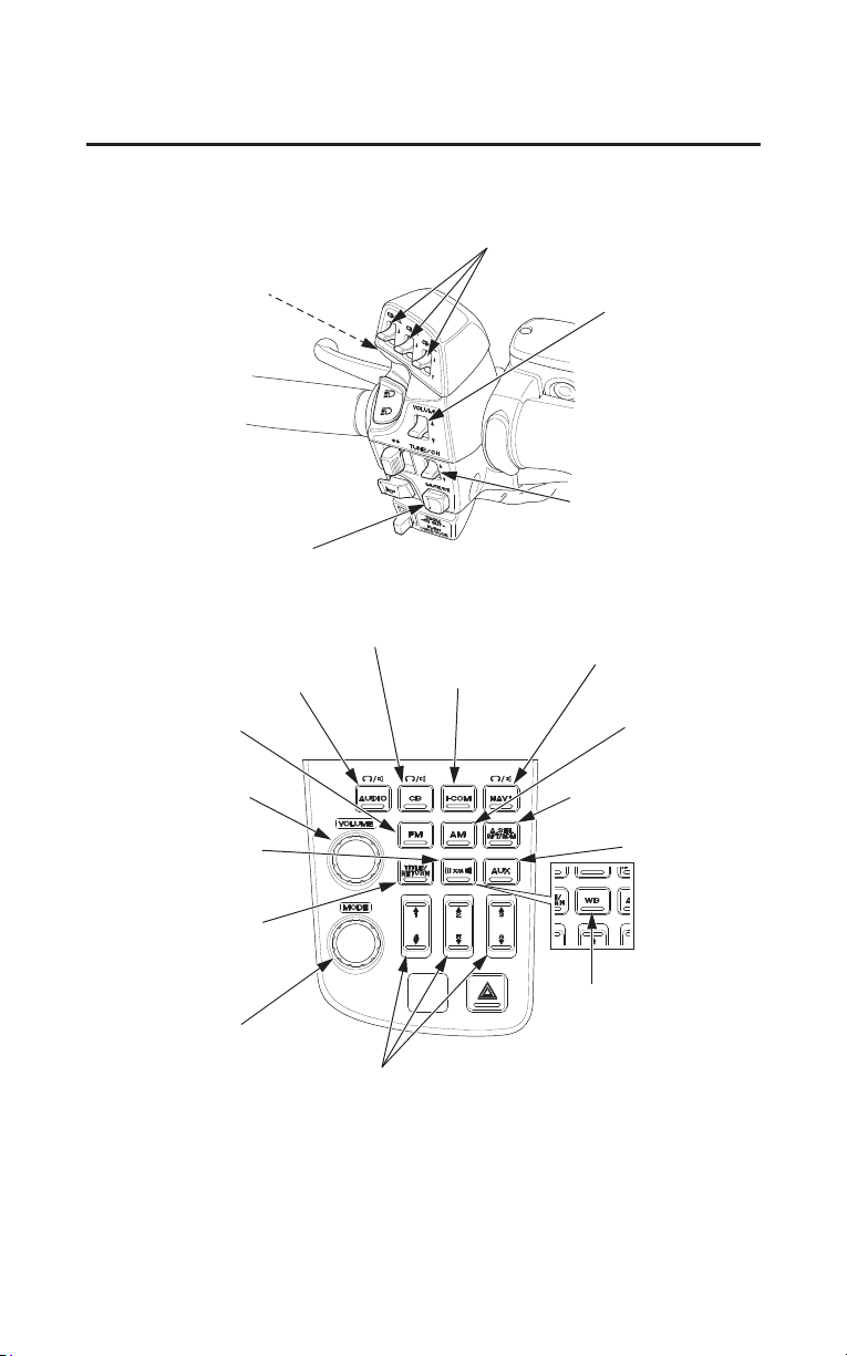
102
Audio Systems
Audio Systems
(Models equipped with Navigation System)
LEFT HANDLEBAR
CB radio levers
(for accessory CB radio)
TALK lever
(for accessory CB radio)
TUNE/CH lever
VOLUME lever
A.SEL
RPT/RDM button
WB button
(For Canada only)
preset buttons
VOLUME
knob/button
FM button
AUDIO button I-COM button
CB button (for accessory CB radio)
NAVI button
AM button
AUX button
MODE
knob/button
TITLE/RETURN
button
XM
®
button
MUTE button
The CB lever and button function when the Honda accessory CB radio is
installed. For CB operating instructions, refer to the accessory manual.
For navigation system operating instructions, refer to the Navigation System
Manual.
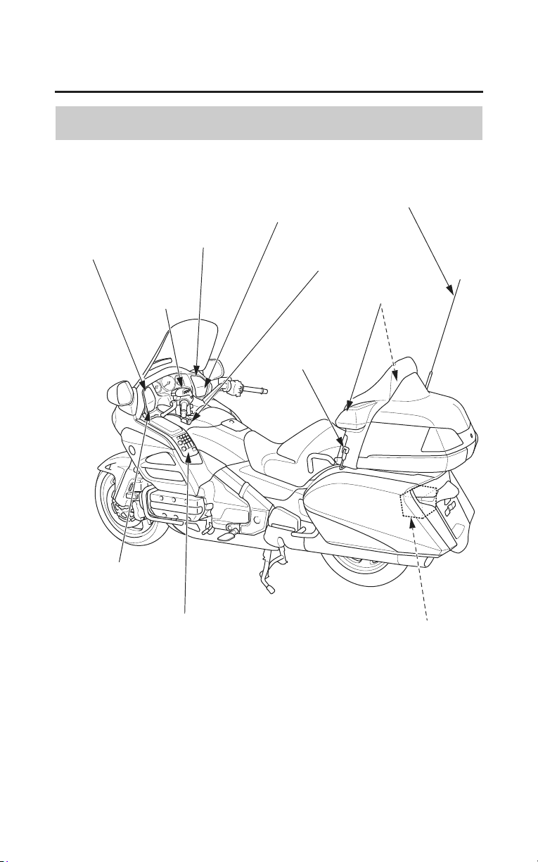
Audio Systems
103
Audio Systems
Audio Component Locations
tweeter
front speaker
front headset
terminal
front speaker
audio system controls
external
amplifier
rear speakers
radio antenna
rear headset
terminal
audio
system
controls
tweeter
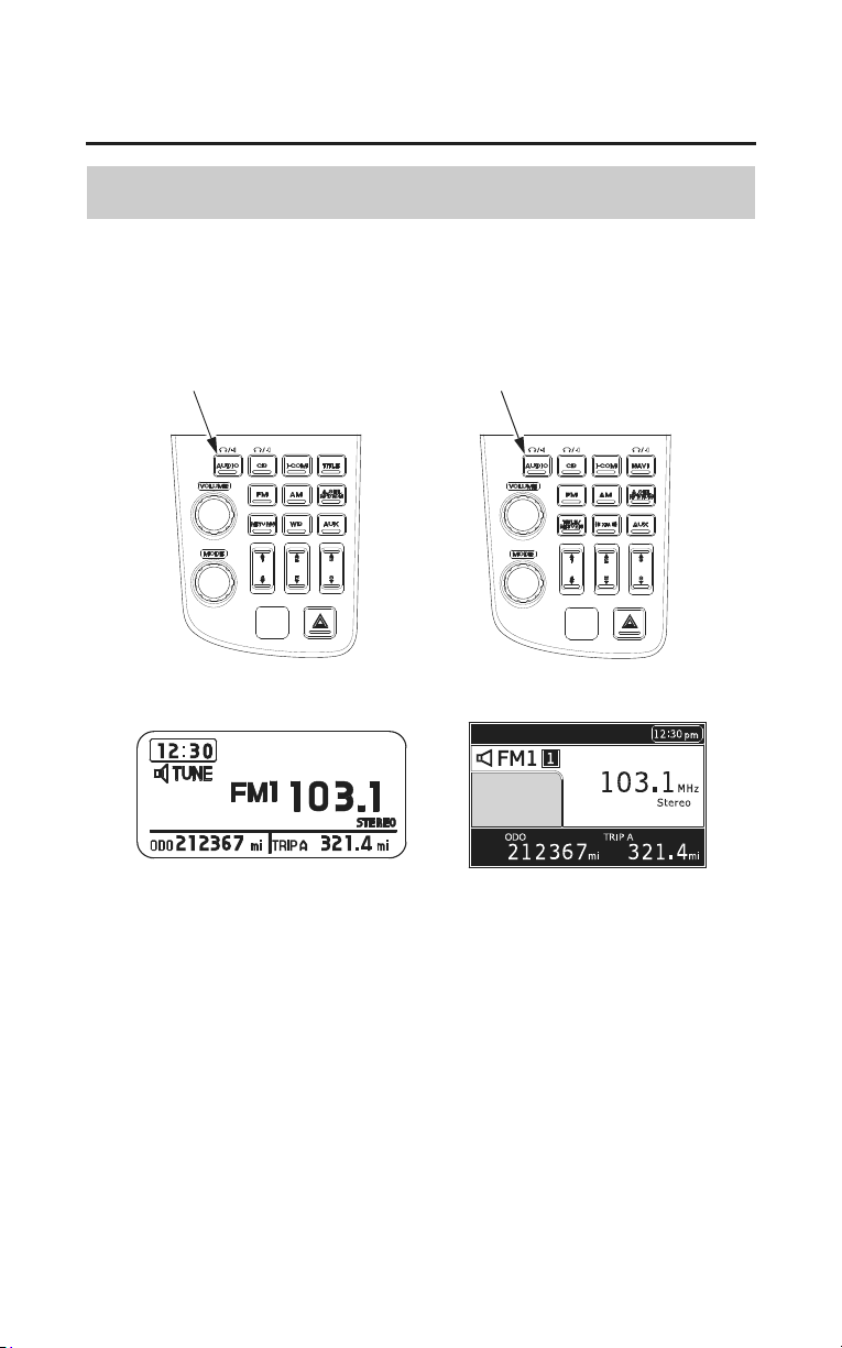
104
Audio Systems
Audio Systems
System Control
To turn the audio system on ï push the AUDIO button.
AUDIO button
(Models not equipped with
Navigation System)
(Models equipped with
Navigation System)
AUDIO button
To turn the audio system off ï push and hold the AUDIO button.
CB is optional equipment. It is only indicated if installed.
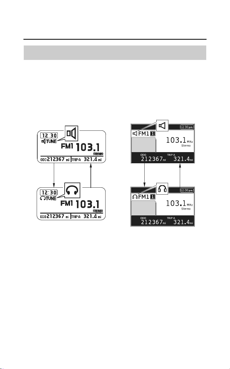
Audio Systems
105
Audio Systems
Switch Output
When the audio system is turned on, you can switch its output between Speaker
and Headset. (Headset is optional equipment.)
• Pushing the AUDIO button switches the output.
(Models not equipped with
Navigation System)
(Models equipped with
Navigation System)
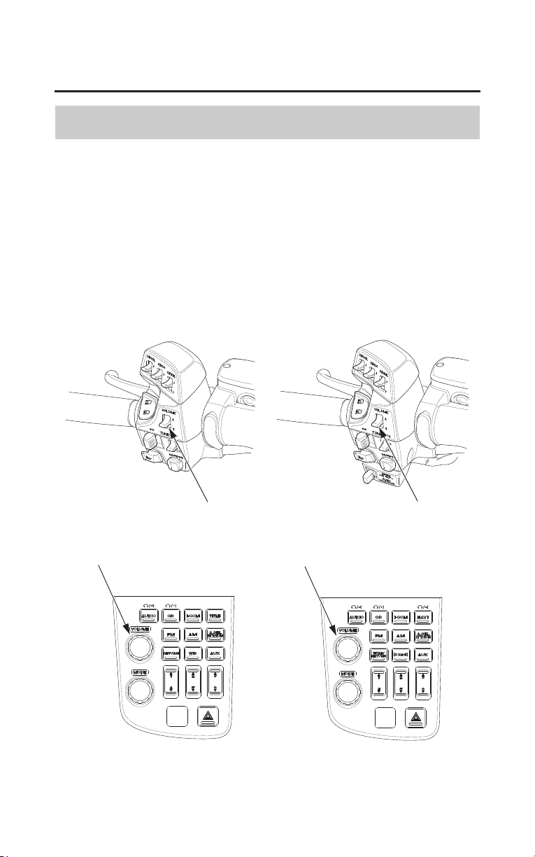
106
Audio Systems
Audio Systems
VOLUME Control
• To increase the volume — push the VOLUME lever up or turn the
VOLUME knob/button clockwise.
• To decrease the volume — push the VOLUME lever down or turn the
VOLUME knob/button counterclockwise.
To increase or decrease the volume rapidly ï push the VOLUME lever up or
down and hold it down.
(VOLUME level range: from 0 to 30)
VOLUME lever
(Models not equipped with
Navigation System)
(Models equipped with
Navigation System)
VOLUME lever
VOLUME knob/button
VOLUME knob/button
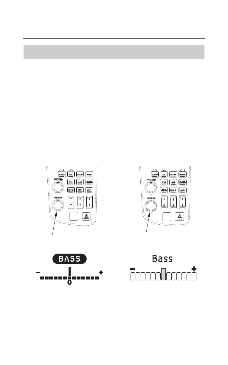
Audio Systems
107
Audio Systems
Tone Control
The tone (Bass ï Treble) is automatically adjusted in accordance with the
vehicle speed.
Bass:
To select the Bass control, push the MODE knob/button until ‘‘BASS’’
(‘‘Bass’’) is displayed (page 97). Then, within 5 seconds, change the bass
control.
• To emphasize bass — turn the MODE knob/button clockwise.
• To reduce bass — turn the MODE knob/button counterclockwise.
(Bass control ranges from 6 down to ï6.)
MODE knob/button
(Models not equipped with
Navigation System)
(Models equipped with
Navigation System)
MODE knob/button
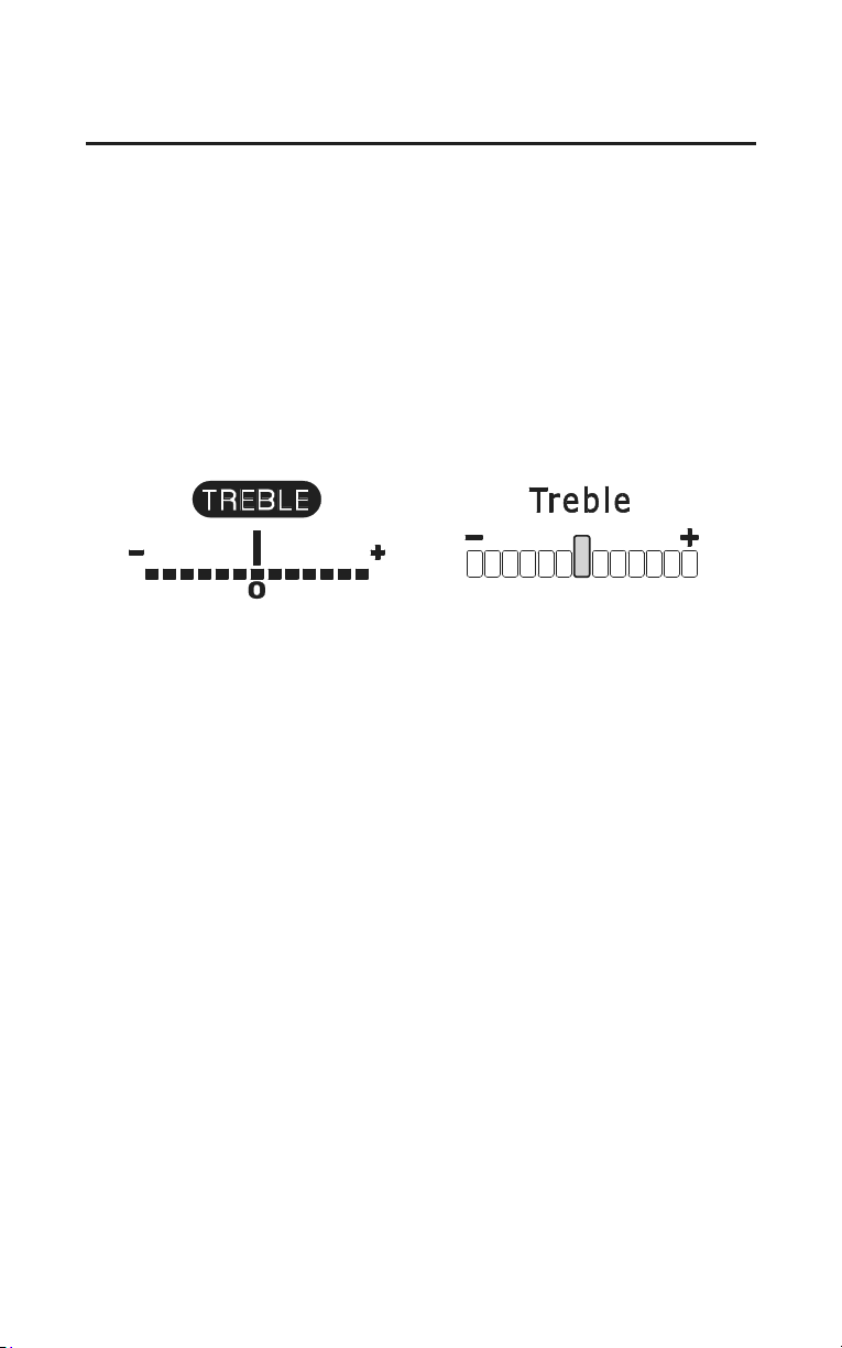
108
Audio Systems
Audio Systems
Treble:
To select the Treble control, push the MODE knob/button until ‘‘TREBLE’’
(‘‘Treble’’) is displayed (page 97). Then, within 5 seconds, change the treble
control.
• To emphasize treble — turn the MODE knob/button clockwise.
• To reduce treble — turn the MODE knob/button counterclockwise.
(Treble level ranges from 6 down to ï6.)
(Models not equipped with
Navigation System)
(Models equipped with
Navigation System)
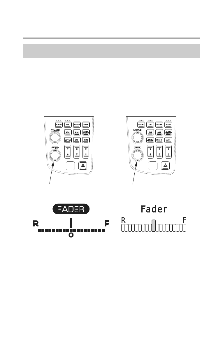
Audio Systems
109
Audio Systems
Fader Control
To balance the sound between the front and rear speakers ï push the MODE
knob/button until ‘‘FADER’’ (‘‘Fader’’) is displayed (page 97). Then, within 5
seconds, change the fader control. (The control range: F (front) and R (rear)
each have 9 segments.)
(Models not equipped with
Navigation System)
(Models equipped with
Navigation System)
MODE knob/button MODE knob/button
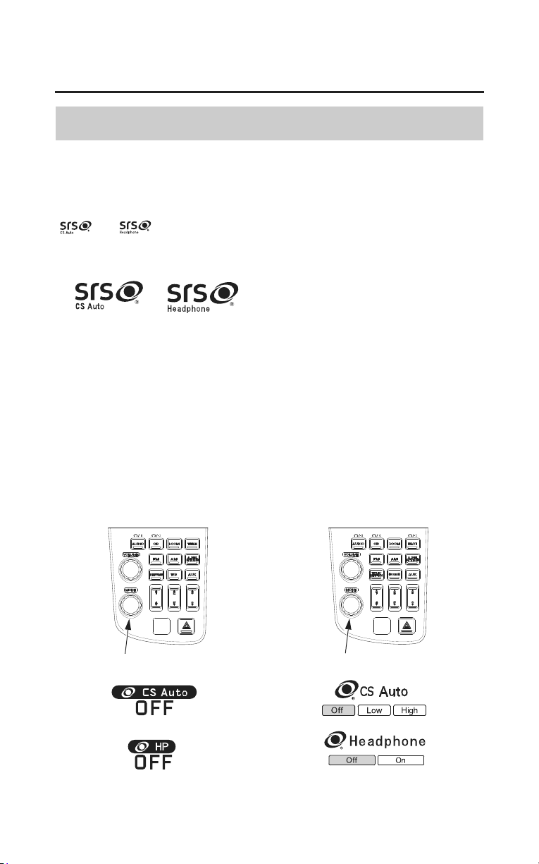
110
Audio Systems
Audio Systems
SRS
SRS CS Auto™ creates a surround sound experience on the motorcycle and
provides rich bass and an elevated audio image.
SRS Headphone™ creates a realistic and immersive 3D stereo headphone
listening experience.
and are trademarks of SRS Labs, Inc.
CS Auto and Headphone technologies are incorporated under license from SRS
Labs, Inc.
• To use the circuit ——– push the MODE knob/button until ‘‘SRS CS Auto’’
is displayed (page 97). To select the SRS of headset,
push the MODE knob/button until ‘‘SRS HP’’ is
displayed. Then, within 5 seconds, change the SRS
setting.
• To change the setting — turn the MODE knob/button.
SRS CS Auto has three settings – HI (High), LOW
(Low), OFF (Off).
SRS HP has two settings – ON (On), OFF (Off).
MODE knob/button
(Models not equipped with
Navigation System)
(Models equipped with
Navigation System)
MODE knob/button
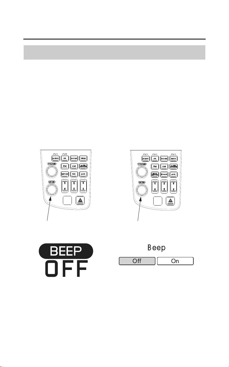
Audio Systems
111
Audio Systems
Beep Set
• To use the circuit ——– push the MODE knob/button until ‘‘BEEP’’
(‘‘Beep’’) is displayed (page 97). Then, within 5
seconds, change the beep setting.
• To change the setting — turn the MODE knob/button. (ON (On) or OFF
(Off))
(Models equipped with Navigation System)
At the same time, the Beep function of the Navigation System is also set.
(Models not equipped with
Navigation System)
(Models equipped with
Navigation System)
MODE knob/button MODE knob/button
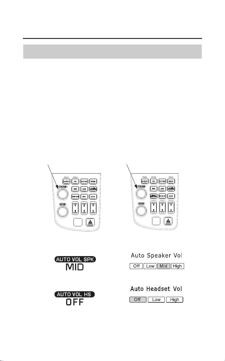
112
Audio Systems
Audio Systems
Auto Volume Control (AVC)
To automatically increase volume as the speed of the motorcycle increases.
Push the VOLUME knob/button until ‘‘AUTO VOL SPK’’ (‘‘Auto Speaker
Vol’’) is displayed (page 98). To select the volume control of headset, push the
VOLUME knob/button until ‘‘AUTO VOL HS’’ (‘‘Auto Headset Vol’’) is
displayed (page 98). Then, within 5 seconds, change the AVC setting.
AUTO VOL SPK has four settings ï HI (High), MID (Mid), LO (Low), and
OFF (Off).
AUTO VOL HS has three settings ï HI (High), LO (Low), and OFF (Off).
VOLUME knob/button
(Models not equipped with
Navigation System)
(Models equipped with
Navigation System)
VOLUME knob/button
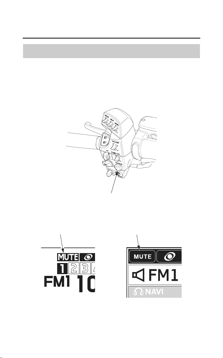
Audio Systems
113
Audio Systems
Muting
To mute the audio and navi volume ï push the MUTE button.
The display will indicate ‘‘MUTE’’.
To restore the original volume ï push the MUTE button again to restore the
original volume.
LEFT HANDLEBAR
MUTE button
(Models not equipped with
Navigation System)
(Models equipped with
Navigation System)
MUTE indicator MUTE indicator
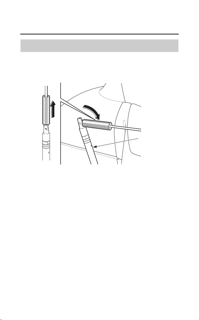
114
Audio Systems
AM/FM Radio
Radio Antenna
To fold the AM/FM radio antenna, pull up on the knurled coupling.
radio antenna
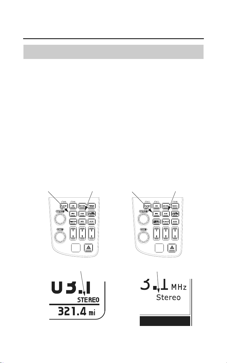
Audio Systems
115
AM/FM Radio
Select Band
(Models not equipped with Navigation System)
Push the FM button to switch to FM1/FM2.
Push the AM button to listen to AM.
(Models equipped with Navigation System)
Push the FM button to switch to FM1/FM2.
Push the AM button to switch to AM/WB (USA only).
Push the AM button to listen to AM (Canada only).
Reception of a stereo signal is indicated whe
n the STEREO indicator appears in
the display. (Stereo reception is available only for FM stereo broadcasts.) As
FM stereo reception becomes weaker, special circuits in the radio gradually
blend the sound toward mono to maintain some sound quality, even though the
STEREO indicator remains ON.
FM button
(Models not equipped with
Navigation System)
(Models equipped with
Navigation System)
FM button AM buttonAM button
STEREO indicator STEREO indicator
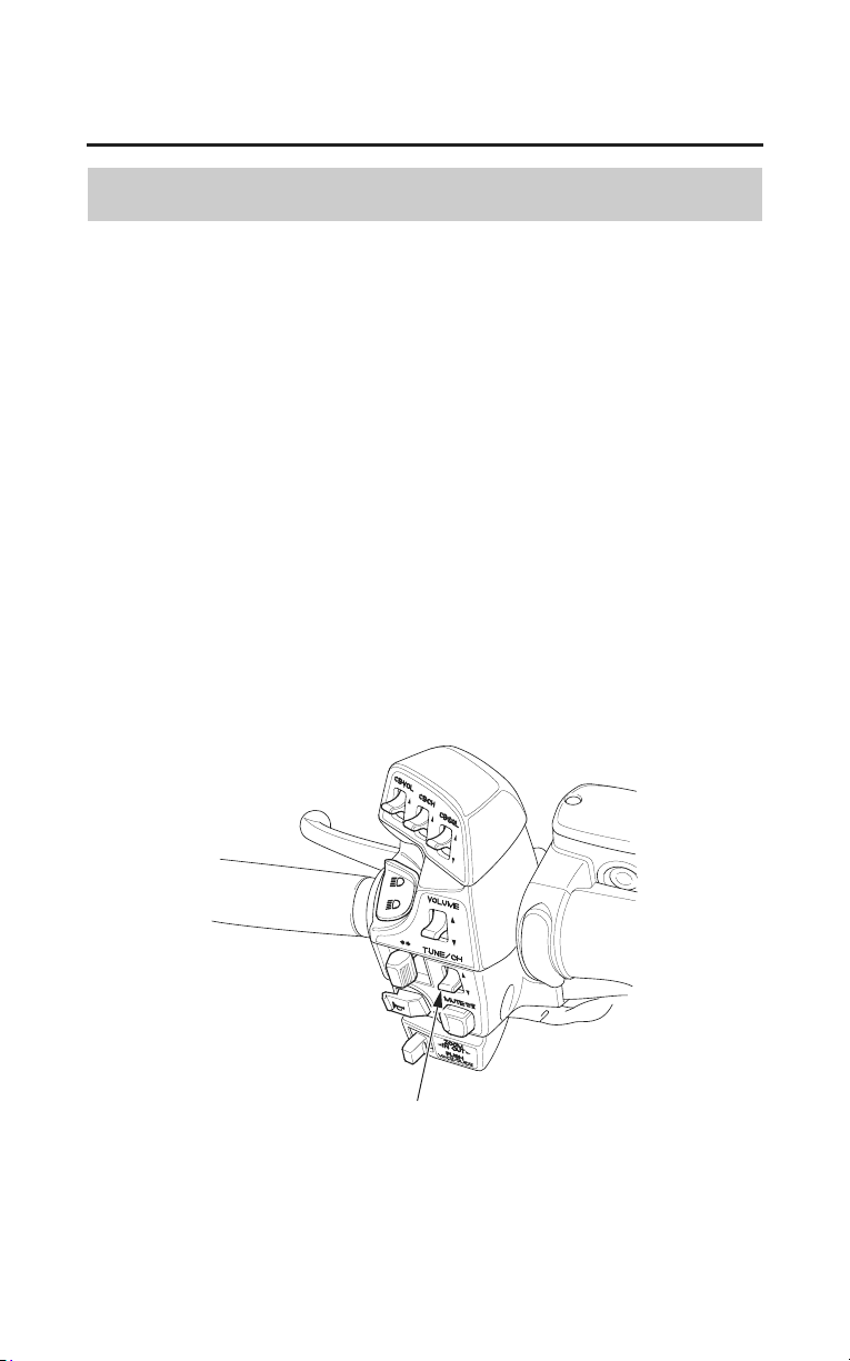
116
Audio Systems
AM/FM Radio
Select Station
To raise the radio frequency ï push the TUNE/CH lever up.
To lower the radio frequency ï push the TUNE/CH lever down.
To move up or down the radio frequencies in sequence, move the lever one click
at a time. The AM frequency display moves in 10 kHz steps. The FM frequency
moves in 0.2 MHz steps.
The SEEK function searches the band for a station with a strong signal. To
activate it, push the TUNE/CH lever up or down and release it. The frequency
display will begin moving. Depending on which way you push the switch, the
system scans upward or downward from the current frequency.
It stops when it finds a station with a strong signal.
When the frequency display reaches either end, it transitions to the other end of
the band and continues in the same direction.
To reach a known frequency rapidly ï p
ush the TUNE/CH lever up or down
and continue to hold it down until you see the desired frequency.
TUNE/CH lever
LEFT HANDLEBAR
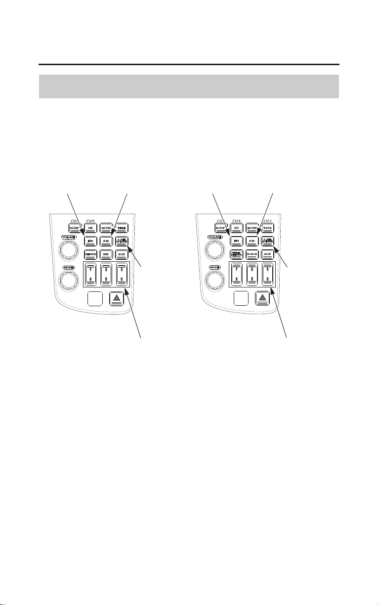
Audio Systems
117
AM/FM Radio
Preset Stations
You can store the frequencies of your favorite radio stations in the six preset
buttons. Each button will store one frequency on the AM band, and two
frequencies on the FM band.
FM button
(Models not equipped with
Navigation System)
(Models equipped with
Navigation System)
FM buttonAM button AM button
A.SEL
RPT/RDM
button
A.SEL
RPT/RDM
button
preset buttons preset buttons
1. Check that A.SEL RPT/RDM is not turned on. If it is on, push the A.SEL
RPT/RDM button to turn it off.
2. Select the desired band, AM or FM. FM1 and FM2 let you store two
frequencies with each Preset button.
3. Use the TUNE or SEEK function to tune the radio to a desired station.
4. Pick the Preset button you want for that station. Press the button and hold it.
5. Repeat steps 1 to 3 to store a total of six stations on AM and twelve on FM.
Once a station’s frequency is stored, simply press and release the proper Preset
button to tune to it. The preset frequencies will be lost if your motorcycle’s
battery goes low (or dead) or is disconnected, or if the radio fuse is removed.
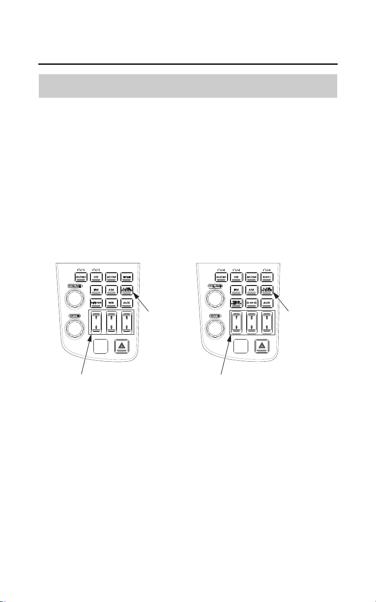
118
Audio Systems
AM/FM Radio
Auto Select
If you are traveling far from home and can no longer receive the stations you
preset, you can use the Auto Select feature to find stations in the local area.
To activate Auto Select, push the A.SEL RPT/RDM button. A.SEL RPT/RDM
will appear in the display, and the system will go into scan mode for several
seconds.
It automatically scans both bands, looking for stations with strong signals. It
stores the frequencies of six AM stations and twelve FM stations in the preset
buttons (page 117). You can then use the preset buttons to select those stations.
preset buttons
(Models not equipped with
Navigation System)
(Models equipped with
Navigation System)
A.SEL
RPT/RDM
button
A.SEL
RPT/RDM
button
preset buttons
If you are in a remote area, Auto Select may not find six strong AM stations or
twelve strong FM stations. If this happens, you will see a ‘‘0’’ displayed when
you push any preset button that does not have a station stored.
With Auto Select on, you cannot manually store any frequencies in the preset
buttons. If you do not like the stations found by Auto Select, you can use the
TUNE and SEEK functions to find other stations.
Auto Select does not erase the frequencies that you preset previously. When you
return home, turn off Auto Select by pressing the A.SEL RPT/RDM button. The
preset buttons will then select the frequencies you originally set.
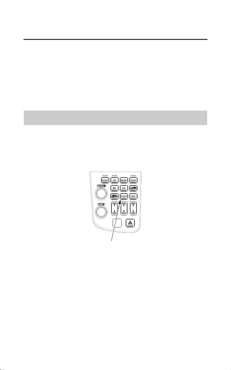
Audio Systems
119
XM
®
Radio (USA only)
(Models equipped with Navigation System)
Your motorcycle is capable of receiving XM
®
Radio anywhere in the United
States, except Hawaii, Alaska and Puerto Rico. XM
®
is a registered trade mark
of Sirius XM Radio
®
, Inc.
XM
®
Radio receives signals from two satellites to produce clear, high-quality
digital reception. It offers many channels in several categories. Along with a
large selection of different types of music, XM
®
Radio also allows you to view
channel and category selections in the audio display.
Receiving XM
®
Radio Service
If your XM
®
Radio service has expired or you purchased your motorcycle from
a previous owner, you can listen to a sampling of the broadcasts available on
XM
®
Radio. With the ignition switch in the ACCESSORY or the ON position,
press the XM
®
button. A variety of music types and styles will play.
XM
®
button
If you decide to purchase XM
®
Radio service, contact XM
®
Radio at
www.xmradio.com, or at 1-800-967-2346 (1-800-XM-RADIO). You will need
to give them your Radio ID number, which may be found on XM
®
Channel 0,
and your credit card number.
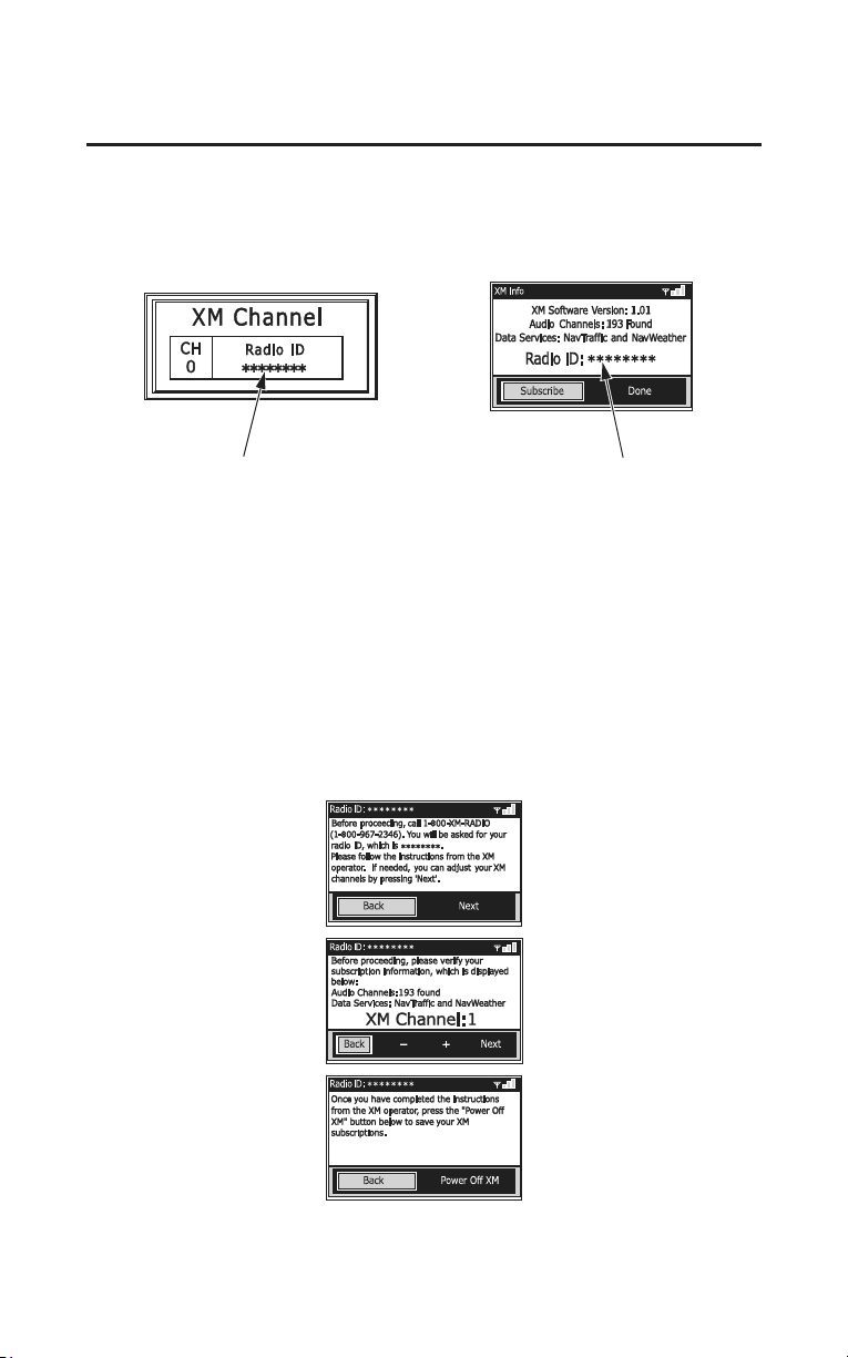
120
Audio Systems
XM
®
Radio (USA only)
To get your Radio ID number, push the TUNE/CH lever until CH 0 appears in
the display under channel mode (Display channel 0 at only ALL Category
search mode) (page 123) or choose Menu screen on the Setup/info menu,
highlight XM
®
Info and press ENT.
Radio ID number Radio ID number
Contact XM
®
Radio at www.xmradio.com, or at 1-800-967-2346 (1-800-XM-
RADIO).
After you’ve registered with XM
®
Radio, keep your audio system in the XM
®
Radio mode while you wait for activation. This should take about 30 minutes.
While waiting for activation, make sure your vehicle remains in an open area
with good reception. XM
®
Radio will continue to send an activation signal to
your motorcycle for at least 3 hours from the activation request. If you miss that
window, simply log onto www.xmradio.com refresh with your Radio ID and
follow the steps to refresh the signal.
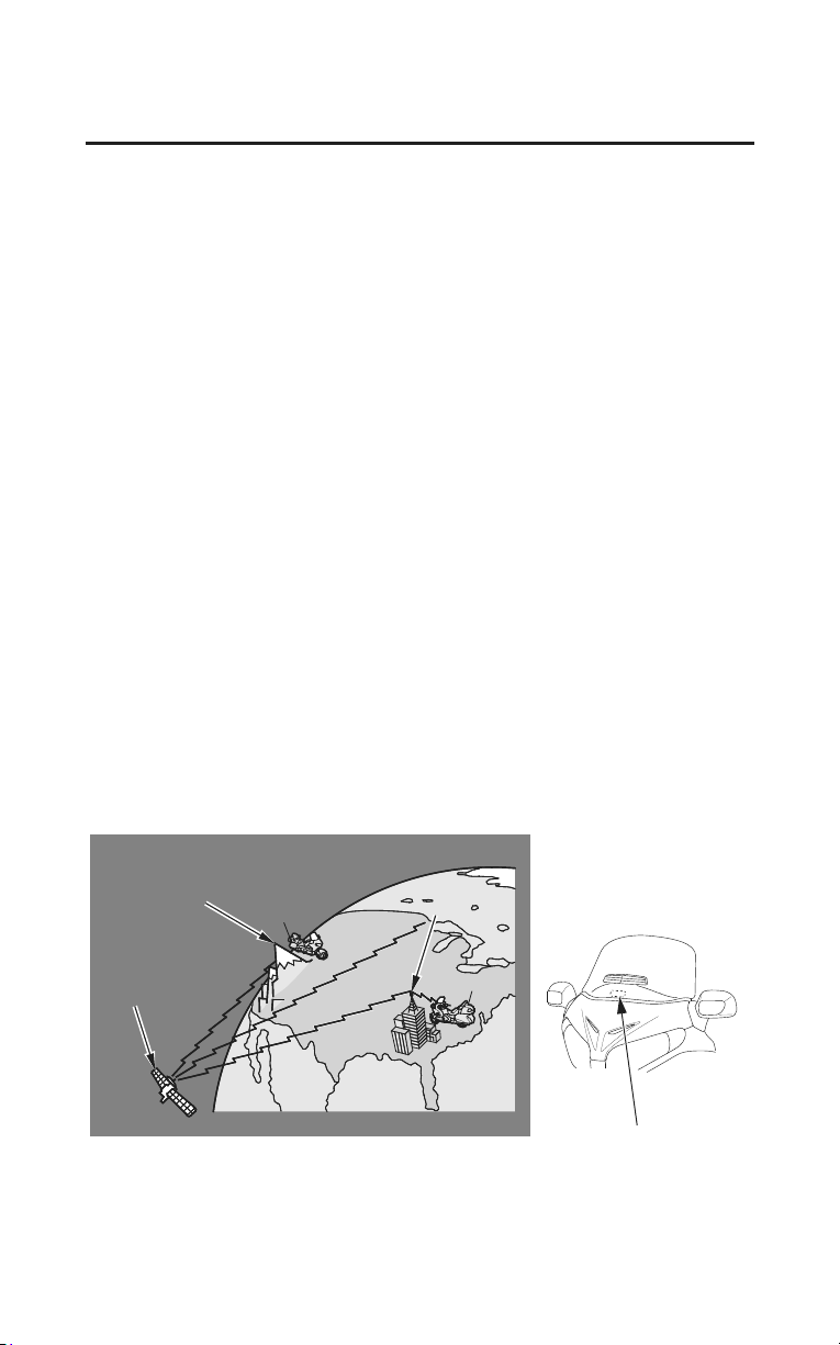
Audio Systems
121
XM
®
Radio (USA only)
The XM
®
satellites are in orbit over the equator; therefore, objects south of the
vehicle may cause satellite reception interruptions. To help compensate for this,
ground-based repeaters are placed in major metropolitan areas.
Satellite signals are more likely to be blocked by tall buildings and mountains
the farther north you travel from the equator. Carrying large items on a travel
trunk can also block the signal.
Depending on where you ride, you may experience reception problems.
Interference can be caused by any of these conditions:
• Riding on the north side of an east/west mountain road.
• Riding on the north side of a large commercial truck on an east/west road.
• Riding in tunnels.
• Riding on a road beside a vertical wall, steep cliff, or hill to the south of you.
• Riding on the lower level of a multi-tiered road.
• Riding on a single-lane road alongside dense trees talle
r than 50 ft. (15 m) to
the south of you.
There may be other geographic situations, parking conditions, and also
installing metallic or metalized accessories near the windscreen could affect
XM
®
Radio reception.
S
S
a
a
t
t
e
e
l
l
l
l
i
i
t
t
e
e
S
S
i
i
g
g
n
n
a
a
l
l
m
m
a
a
y
y
b
b
e
e
b
b
l
l
o
o
c
c
k
k
e
e
d
d
b
b
y
y
m
m
o
o
u
u
n
n
t
t
a
a
i
i
n
n
s
s
o
o
r
r
l
l
a
a
r
r
g
g
e
e
o
o
b
b
s
s
t
t
a
a
c
c
l
l
e
e
s
s
t
t
o
o
t
t
h
h
e
e
s
s
o
o
u
u
t
t
h
h
.
.
G
G
r
r
o
o
u
u
n
n
d
d
r
r
e
e
p
p
e
e
a
a
t
t
e
e
r
r
Signal is weaker in these areas.
XM
®
radio antenna
As required by the FCC:
Changes or modifications not expressly approved by the party responsible for
compliance could void the user’s authority to operate the equipment.
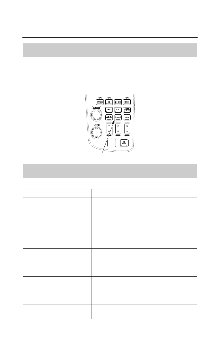
122
Audio Systems
XM
®
Radio (USA only)
Operating the XM
®
Radio
To listen to XM
®
Radio, turn the ignition switch to the ON or ACCESSORY
position, and push the XM
®
button. The last channel you listened to will show
in the display.
Push the XM
®
button to switch to XM1/XM2/XM3.
XM
®
button
XM Radio Display Messages
‘LOADING’
XM
®
is loading the audio or program
information.
‘OFF AIR’ The channel currently selected is no longer
broadcasting.
‘UPDATING’ The encryption code is being updated. Wait
until the encr
yption code is fully updated.
Channels 0 and 1 should still work normally.
‘NO XM SIGNAL’ The signal is currently too weak. Move the
vehicle to an area away from tall buildings,
and with an unobstructed view of the
southern horizon.
‘ ï ï ï ï ’ The selected channel number does not exist,
or is not part of your subscription, or this
channel has no artist or title information at
this time.
‘CHECK XM ANTENNA’
There is a problem with the XM
®
antenna.
Please consult your dealer.
Display Message Status
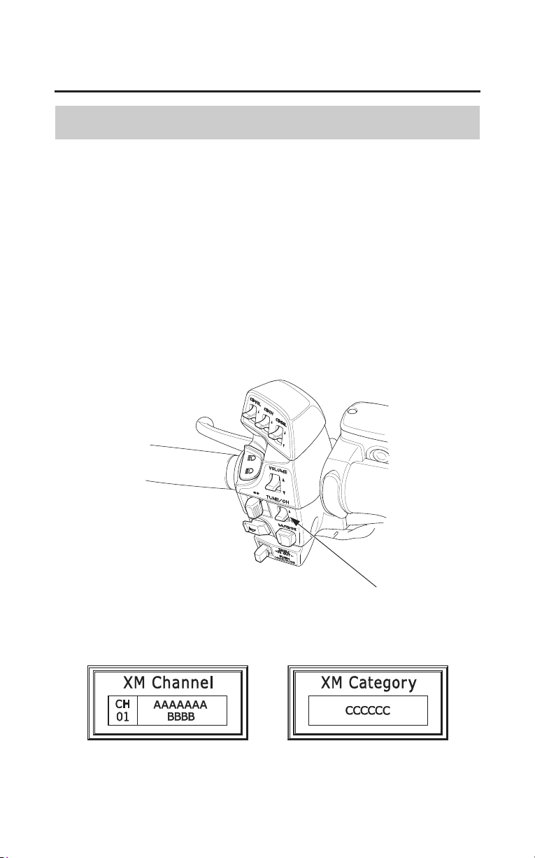
Audio Systems
123
XM
®
Radio (USA only)
Select Channel
To select channel from XM
®
Channel, push the TUNE/CH lever.
To select channel from XM
®
Category, push and hold the TUNE/CH lever then
select the category while XM
®
Category is displaying.
Push the TUNE/CH lever up or down and continue to hold it down until you see
the desired channel.
In the channel mode, you can select all of the available channels. In the category
mode, such as Jazz, Rock, Classical, etc., you can select all of the channels
within that category.
You may experience periods when XM
®
Radio does not transmit the artist’s
name and song title information. If this happens, there is nothing wrong with
your system.
XM
®
Channel
TUNE/CH lever
XM
®
Category
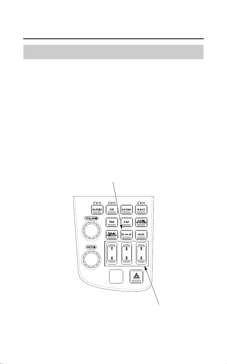
124
Audio Systems
XM
®
Radio (USA only)
Preset Channel
You can store the channels of your favorite up to 18 preset channels using the
six preset buttons. Each button stores one channel from the XM1 band, one
channel from the XM2 band and one channel from the XM3 band.
1. Push the XM
®
button to select XM1, XM2 or XM3.
2. Select the channel (page 123).
3. Pick the Preset button you want for that channels. Press and hold the preset
button until you hear a beep.
4. Repeat steps 2 and 3 to store a total of six channels on each XM1, XM2 and
XM3.
Once a channel is stored, simply press and release the proper preset button to
tune
to it. The preset channels will be lost if your motorcycle’s battery goes low
(or dead) or is disconnected, or if the radio fuse is removed.
preset buttons
XM
®
button
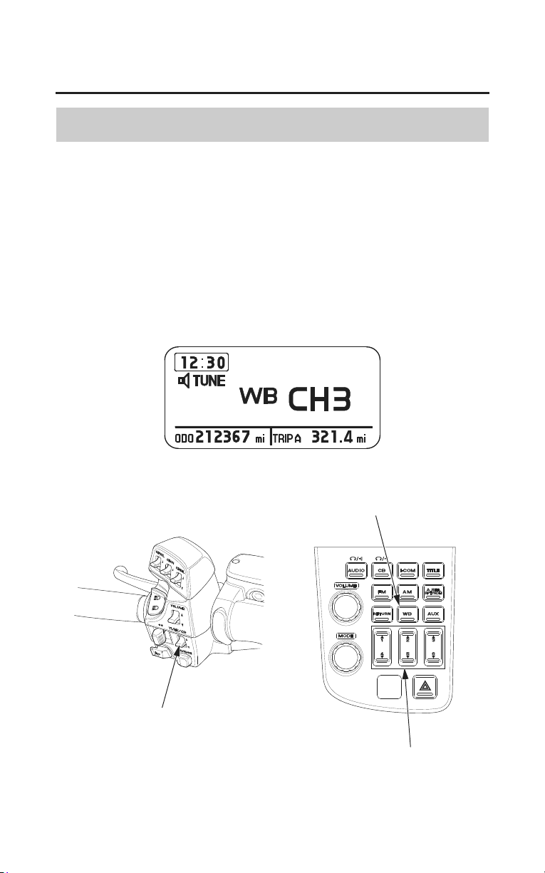
Audio Systems
125
Weather Information
Weather Band (WB)
(Models not equipped with Navigation System)
To listen to the Weather Band — push the WB button.
To cancel the Weather Band — push another button (AM, FM or AUX).
To select channels 1 – 6 — push the desired preset button.
To select channel 7 — push the TUNE/CH lever up or down until channel 7 is
selected.
(The TUNE/CH lever may be used to select any of the 7 channels. The lever
must be used to select channel 7.)
WB button
preset buttons
TUNE/CH lever
LEFT HANDLEBAR
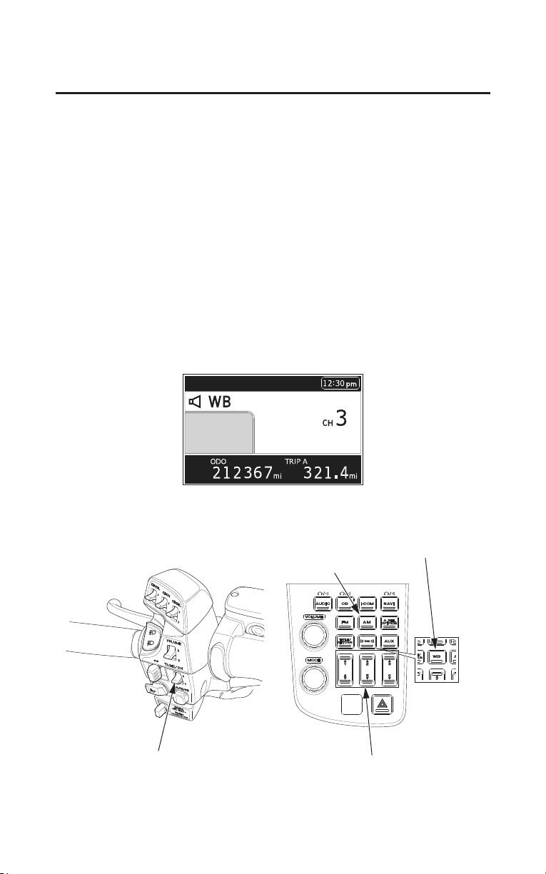
126
Audio Systems
Weather Information
(Models equipped with Navigation System)
For USA
To listen to the Weather Band — push the AM button to switch AM/WB.
To cancel the Weather Band — push the AM button again or another button
(FM, XM
®
or AUX).
For Canada
To listen to the Weather Band — push the WB button.
To cancel the Weather Band — push another button (AM, FM or AUX).
To select channels 1 – 6 — push the desired preset button.
To select channel 7 — push the TUNE/CH lever up or down until channel 7 is
selected.
(The TUNE/CH lever may be used to select any of the 7 channels. The lever
must be used to select channel 7.)
AM button
LEFT HANDLEBAR
preset buttons
TUNE/CH lever
WB button
(For Canada only)
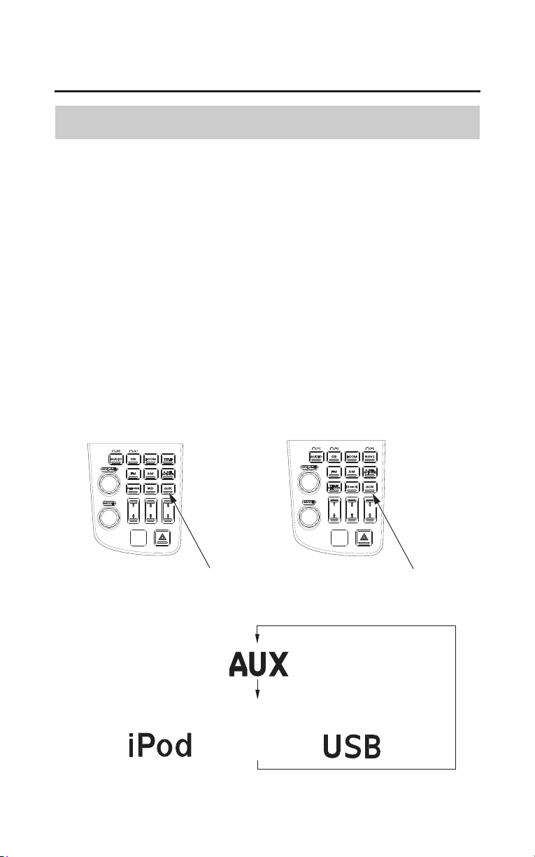
Audio Systems
127
Auxiliary Function
Auxiliary (AUX) Input
Use this function to listen to other audio:
Connect the input jack connector to listen to other audios.
Connect the iPod
®
/USB flash drive to the USB cable to operate and listen to it
(see page 130).
• To turn the function on — push the AUX button once. (AUX appears on the
display.)
push the AUX button twice when connecting a
USB device with USB cable (see page 134).
(iPod
®
or USB appears on the display.)
• To turn the function off — push the AM, FM, XM
®
or WB button.
The following functions operate the same as they do with the AM/FM radio:
Switch output, Tone control, Fader control, SRS, AVC, BEEP, Muting.
(Models not equipped with
Navigation System)
(Models equipped with
Navigation System)
AUX button AUX button
The display changes as follows each time the AUX button is pushed.
RU
(When connecting a iPod
®
or USB flash drive with USB cable)
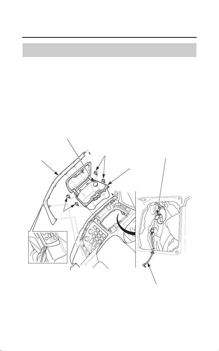
128
Audio Systems
Auxiliary Function
Input Jack Setup
(Models equipped with Navigation System)
The auxiliary input jack connector is located under the left fairing pocket. To
use it:
1. Attach a cloth to the cover and remove the cover with care using a flat-tip
screwdriver.
2. Open the left fairing pocket cover and remove the clips and grommet A.
3. Lift out the fairing pocket.
auxiliary input patch cord
cover
grommet A
fairing pocket
clips
wire harness connector
clips
4. Remove the auxiliary input patch cord from the owner’s manual pouch.
5. Plug the auxiliary input patch cord into the wire harness connector.
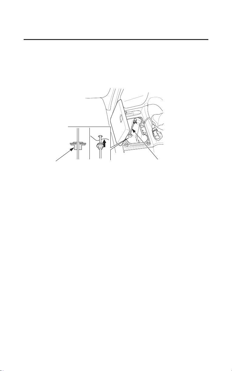
Audio Systems
129
Auxiliary Function
6. Route the auxiliary input patch cord through the hole in the bottom of the
fairing pocket.
7. Install the grommet B to left fairing pocket.
Do not pull on the auxiliary cord as the wires could be damaged.
grommet B
auxiliary input
patch cord
• Some portable audio systems may pick up noise from the ignition.
• Adjust the volume of the portable audio system so that it is about the same
level as the GL’s radio volume. If the volume of the portable audio system is
set too high, the sound coming out from the speakers or headset may be
distorted.
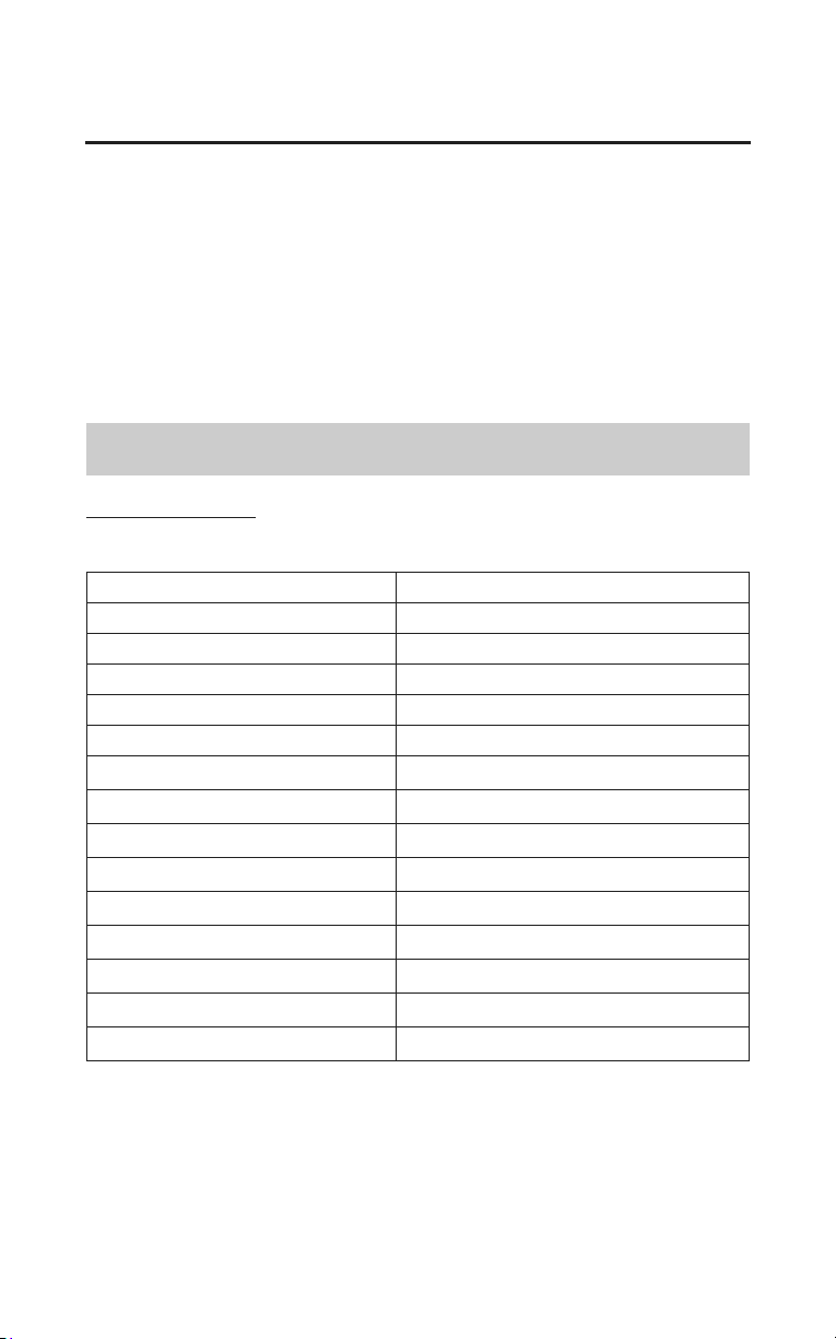
130
Audio Systems
iPod
®
/USB Flash Drive
This audio system can play the audio files on the iPod
®
and a USB flash drive.
To play an iPod
®
or a USB flash drive, connect it to the USB cable in the trunk
(page 134).
iPod touch
®
, iPod
®
, iPod nano
®
are registered trademarks of Apple Inc. in the
U.S. and other countries.
Use any USB flash drive and iPod
®
at your own risk.
In no event shall Honda be liable for any damages or troubles in use.
Playable iPod
®
/USB Flash Drive
Compatible Devices
iPods
®
and USB flash drives compatible with your audio system are:
USB flash drive 256 M bytes or more
Hard disk drive Not support
Card reader/Memory reader Not support
CD/DVD/FD drive Not support
USB hub Not support
iPod nano
®
1st generation
F/W Ver. 1.2.0 or later
iPod nano
®
2nd generation
F/W Ver. 1.1.2 or later
iPod nano
®
3rd generation
F/W Ver. 1.0.0 or later
iPod nano
®
4th generation
F/W Ver. 1.0.0 or later
iPod nano
®
5th generation
F/W Ver. 1.0.0 or later
iPod nano
®
6th generation
F/W Ver. 1.0.0 or later
iPod touch
®
1st generation
F/W Ver. 1.2.0 or later
iPod touch
®
2nd generation
F/W Ver. 1.0.0 or later
iPod touch
®
3rd generation
F/W Ver. 4.2.0 or later
Device Support Requirements
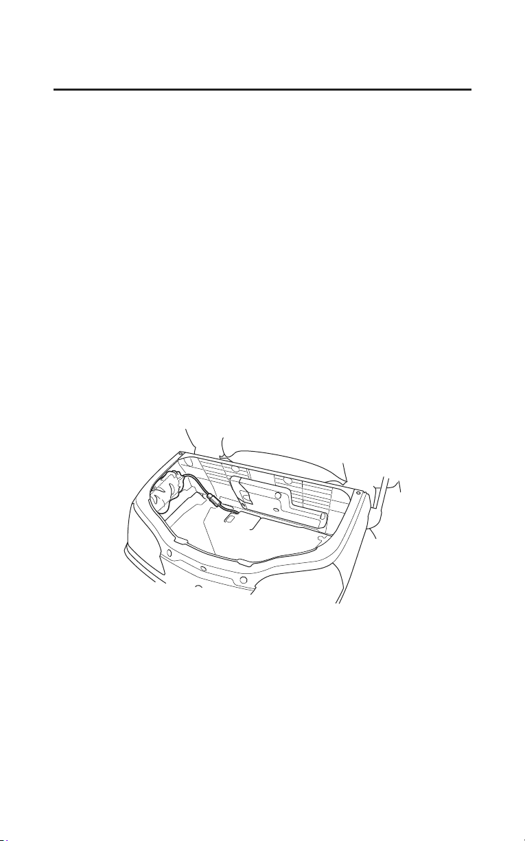
Audio Systems
131
iPod
®
/USB Flash Drive
• Do not leave iPods
®
/USB flash drives in the vehicle (trunk). High heat will
damage it.
• Read precaution statements on the provided instructions of your iPods
®
/USB
flash drives.
•Use iPod
®
with the latest version of firmware.
• Some USB flash drives (such as devices with security lockout features, etc.)
may not be used or restricted to its function.
• Some USB flash drives maybe unsupported or incompatible and will cause
abnormal audio function, such as skipping or playing delays.
• Do not use hard disks, card readers, and memory readers which may damage
the device and data. If you accidentally connect the one of them, turn the
ignition switch OFF and remove it.
• We recommend backing up your data before playing it.
•iPods
®
or some of USB flash drives can be charged with the USB cable when
the ignition switch is in the ON or ACC position. The charging time may be
longer than usual.
• We recommend covering your iPods
®
/USB flash drives with Honda
accessory audio pouch, or soft fabric or cover to protect from damage.
• Be careful to not get the USB connector wet.
• Do not connect with a hub.
• Do not connect incompatible iPods
®
/USB flash drives.
• Music information may not be displayed. If the character code in use is not
supported, ‘‘ . ’’ will be displayed.
• If the audio system does not recognize the iPod
®
, try reconnecting it a few
times or reboot the device.
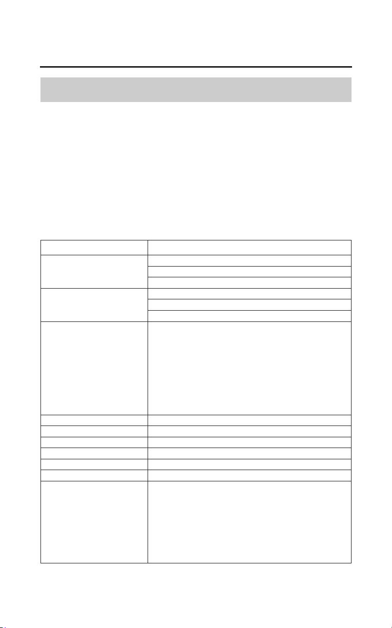
132
Audio Systems
iPod
®
/USB Flash Drive
Playable music files
In the audio function, MP3/WMA music files in USB flash drives can be
played.
Read the followings before recording files in your USB flash drives which may
have restrictions.
• Do not edit other type of extension. Playing USB flash drives containing
these kind of files can cause troubles such as the device or speakers failure.
MP3/WMA files in your USB flash drives can be played on the following
specifications.
Items Contents
Standards MPEG1 Audio Layer 2, 3
MPEG2 Audio Layer 2, 3
MPEG2.5 Audio Layer 2, 3
Sampling periodicity
(kHz)
MPEG1 32/44.1/48 kHz
MPEG2 16/22.05/24 kHz
MPEG2.5 8/11.025/12 kHz
Bit rates (kbit/s) MPEG1 Audio Layer 2: 32-384/VBR/CBR
MPEG1 Audio Layer 3: 32-320/VBR/CBR
MPEG2 Audio Layer 2: 8-160/VBR/CBR
MPEG2 Audio Layer 3: 8-160/VBR/CBR
MPEG2.5 Audio Layer 3: 8-160/VBR/CBR
If the files are low bit rate and/or small data
size, you may not be played the files.
File systems FAT12/16/32
Channel modes Stereo/Joint stereo/Dual channel/Monaural
Maximum hierarchies 8 hierarchies (including the root directory)
Maximum folders 999 folders
Maximum files 65,025 files (255 files in one folder)
Available tags ID3v1(v1.0/v1.1), ID3v2(v2.2/v2.3/v2.4)
Available number of
char
acters
Models not equipped with Navigation System
max: 16 characters
Models equipped with Navigation System
max: 32 characters
(According to the character code or the number
of songs, the maximum number of characters
may not be displayed.)
MP3

Items Contents
Standards Windows Media Audio Version 7/8/9
Sampling periodicity
(kHz)
32/44.1/48
Bit rates (kbit/s) 48-320/VBR
File systems FAT 12/16/32
Channel modes Stereo/Monaural
Maximum hierarchies 8 hierarchies
(including the root directory)
Maximum folders 999 folders
Maximum files 65,025 files
(255 files in one folder)
Available tags WMA: ASF TOP-LEVEL HEADER OBJECT
Only songs, artists and albums available.
(The albums registered by Windows Media
Pla
yer is only available.)
Available number of
characters
Models not equipped with Navigation System
max: 16 characters
Models equipped with Navigation System
max: 32 characters
(According to the character code or the number
o
f songs, the maximum number of characters
may not be displayed.)
Audio Systems
133
iPod
®
/USB Flash Drive
WMA
Windows Media is registered trademarks of Microsoft Corporation. in the U.S.
and other countries.
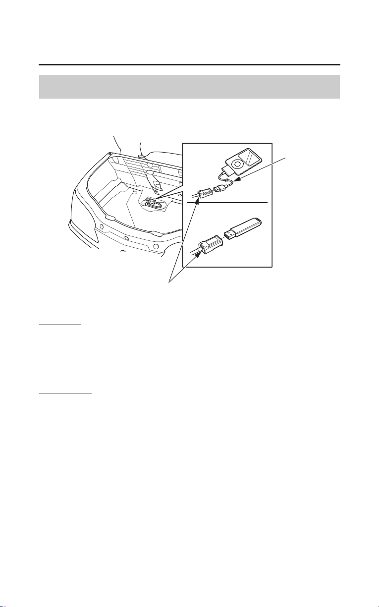
134
Audio Systems
iPod
®
/USB Flash Drive
USB Cable
USB connector
dock
connector
To connect
1. Open the trunk (see page 53) and turn over the trunk mat.
2. Unclip the USB connector.
3. Connect your iPod with dock connector or the USB flash drive to the USB
connector.
To disconnect
You can disconnect the iPod
®
/USB flash drive at any time. Make sure to follow
the iPod
®
’s instructions on how to disconnect the dock connector from the USB
cable.
When you disconnect the iPod
®
/USB flash drive, the USB indicator will
disappear.
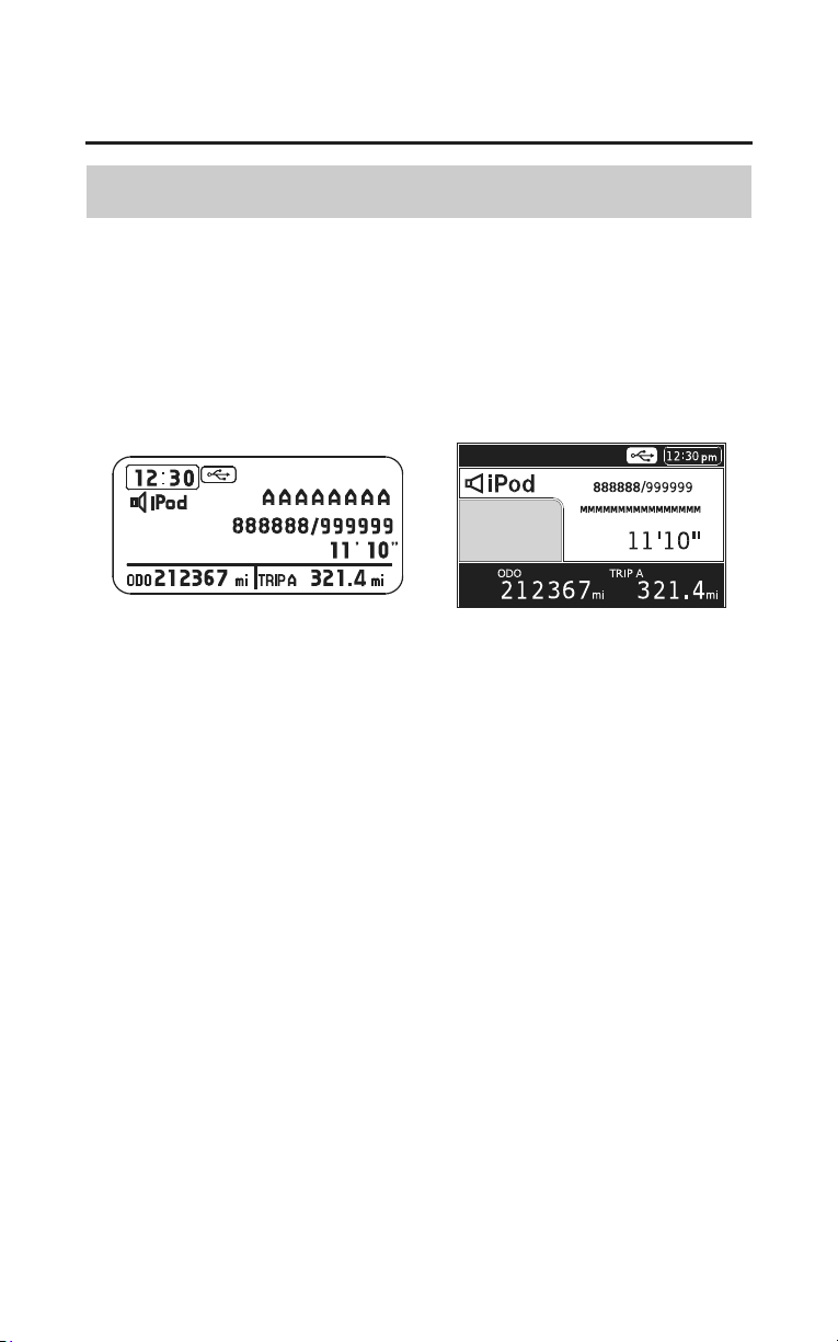
Audio Systems
135
iPod
®
/USB Flash Drive
Playing an iPod
®
Connect the iPod
®
using your dock connector to the USB cable (see page 134),
then push the AUX button twice and iPod
®
indicator will be displayed.
If you see an error message in the display, see page 143.
(Models not equipped with
Navigation System)
(Models equipped with
Navigation System)
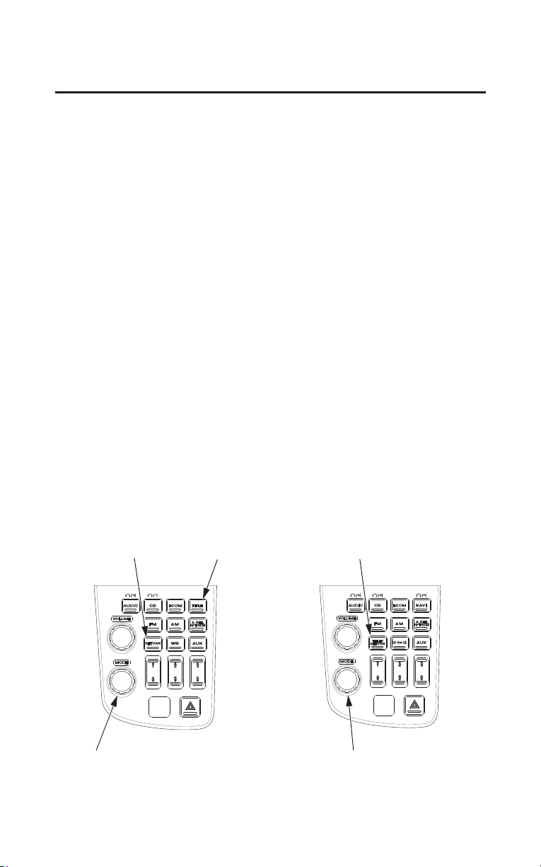
136
Audio Systems
iPod
®
/USB Flash Drive
Select a playlist, artist, album and song by using the MODE knob/button. Push
the MODE knob/button until iPod
®
menu is displayed, then turn the
MODE knob/button until the desired list. Push the MODE knob/button to set
your selection.
The display shows items on the selected list. Turn the MODE knob/button to
select an item, then push the MODE knob/button to set your selection.
If you select ‘‘ALL’’, all available files on the selected list are played.
Selecting ‘‘RETURN’’ goes back to the previous display.
(Models not equipped with Navigation System)
Push the TITLE button to change the title displa
y of albums, songs and artists.
Push and hold the TITLE button to display the text data of albums, songs and
artists from first 8 characters to next 8 characters.
Push the RETURN button to go back to the previous menu while selecting a
playlist, artist, album and song.
(Models equipped with Navigation System)
Push the TITLE/RETURN button to change the title display of albums, songs
and artists.
Push and hold the TITLE/RETURN button to display the text data of albums,
songs and artists from first 16 characters to next 16 characters.
Push the TITLE/RETURN button to go back to the previous menu while
selecting a playlist, artist, album and song.
MODE knob/button
(Models not equipped with
Navigation System)
(Models equipped with
Navigation System)
MODE knob/button
TITLE/RETURN buttonTITLE buttonRETURN button

Audio Systems
137
iPod
®
/USB Flash Drive
You can also change or select playlists, artists and albums on the iPod
®
menu,
use the TUNE/CH lever (see page 138).
Use the TUNE/CH lever while an iPod
®
is playing to change files.
Push the TUNE/CH lever up to change to the next file.
Push the TUNE/CH lever down to change to the previous file.
TUNE/CH lever
(Models not equipped with
Navigation System)
(Models equipped with
Navigation System)
TUNE/CH lever
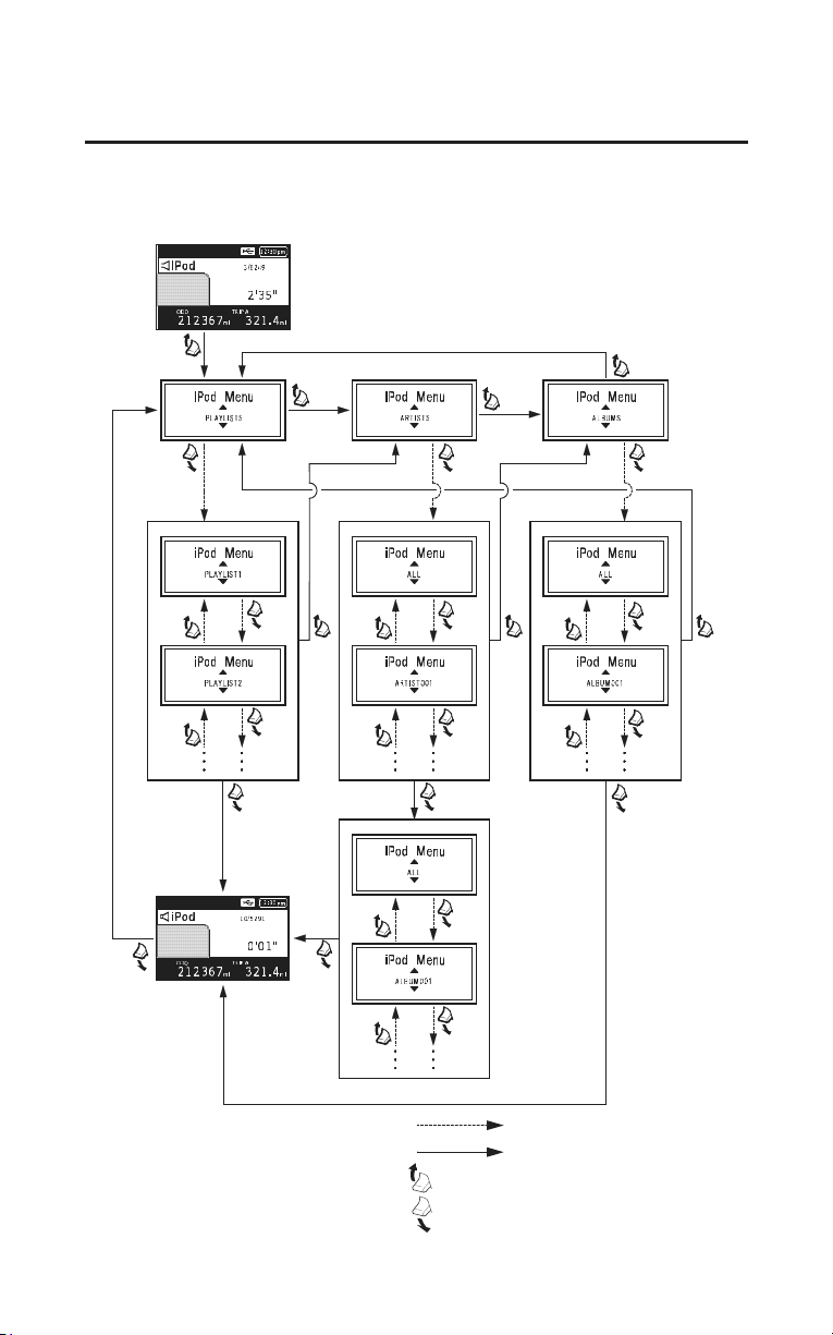
138
Audio Systems
iPod
®
/USB Flash Drive
Illustrations are models equipped with Navigation System. Functions and flows
of models not equipped with Navigation System are same as models equipped
with Navigation System.
Push the TUNE/CH lever:
Push and hold the TUNE/CH lever:
Push the TUNE/CH lever up:
Push the TUNE/CH lever down:
Play 1st
track of
selected
playlist
Play 1st track
of selected
album
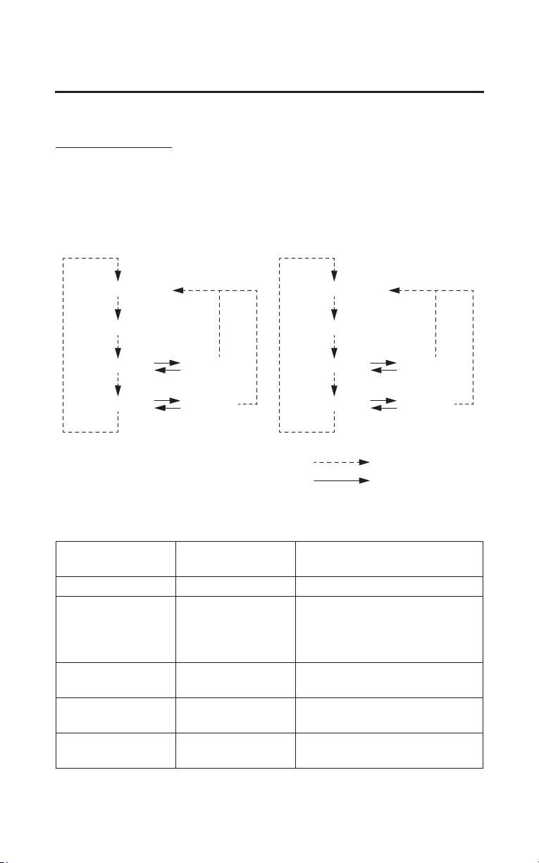
Audio Systems
139
iPod
®
/USB Flash Drive
You can select repeat and random play modes when playing a file.
To select a play mode
Push the A.SEL RPT/RDM button until the desired play mode is displayed.
The display changes as follows each time the A.SEL RPT/RDM button is
pushed.
NO DISPLAY
T.R PT
T.R DM
A.RDM
RT.RPT
AT.RP T
NO DISPLAY
RPT
SHU
A.SHU
SHU RPT
A.SHU
RPT
(Models not equipped with
Navigation System)
(Models equipped with
Navigation System)
Push the A.SEL RPT/RDM button:
Push and hold the A.SEL RPT/RDM button:
T.RP T RPT
T.RDM SHU
A.RDM A.SHU
RT.RPT SHU RPT
AT. RP T
A.SHU
RPT
Play Mode Menu Items
Not equipped with
Navigation
Equipped with
Navigation
Function
Repeats the current track.
Plays all available files in a
sel
ected list (playlists, artists,
albums or songs) in random
order.
Plays all available albums in
random order.
Repeats current file in T.RDM/
SHU play mode.
Repeats current file in A.RDM/
A.SHU play mode.
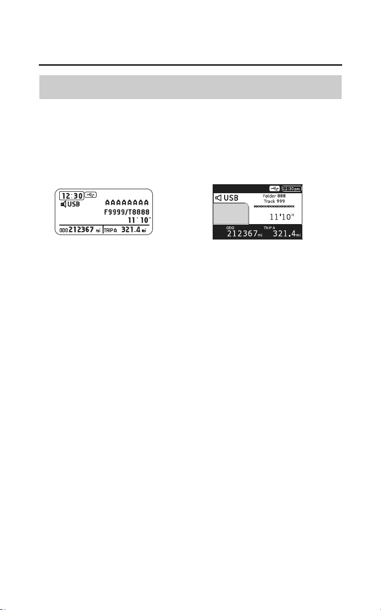
140
Audio Systems
iPod
®
/USB Flash Drive
Playing a USB Flash Drive
Connect your USB flash drive to the USB cable (see page 134), then push the
AUX button twice and USB indicator will be displayed.
If you see an error message in the display, see page 143.
(Models not equipped with
Navigation System)
(Models equipped with
Navigation System)
Select a folder or file by using the MODE knob/button. Push the MODE knob/
button until USB menu is displayed, then turn the MODE knob/button until the
desired folder or file list. Push the MODE knob/button to set your selection.
The display shows items on the selected list. Turn the MODE knob/button to
select an item, then push the MODE knob/button to set your selection.
Selecting ‘‘RETURN’’ goes back to the previous display.
Files on the USB flash drive are played in their stored order. This order may be
different from the order displayed on your PC or device.
(Models not equipped with Navigation System)
Push the TITLE button to change the title display
of folders, files, artists,
albums and songs.
Push and hold the TITLE button to display the text data of from first 8
characters to next 8 characters.
Push the RETURN button to go back to the previous menu while selecting a
folder, file, artist, album and song.
(Models equipped with Navigation System)
Push the TITLE/RETURN button to change the title display of folders, files,
artists, albums and songs.
Push and hold the TITLE/RETURN button to display the text data of folders
from first 16 characters to next 16 characters.
Push the TITLE/RETURN button to go back to the previous menu while
selecting a folder, file, artist, album and song.
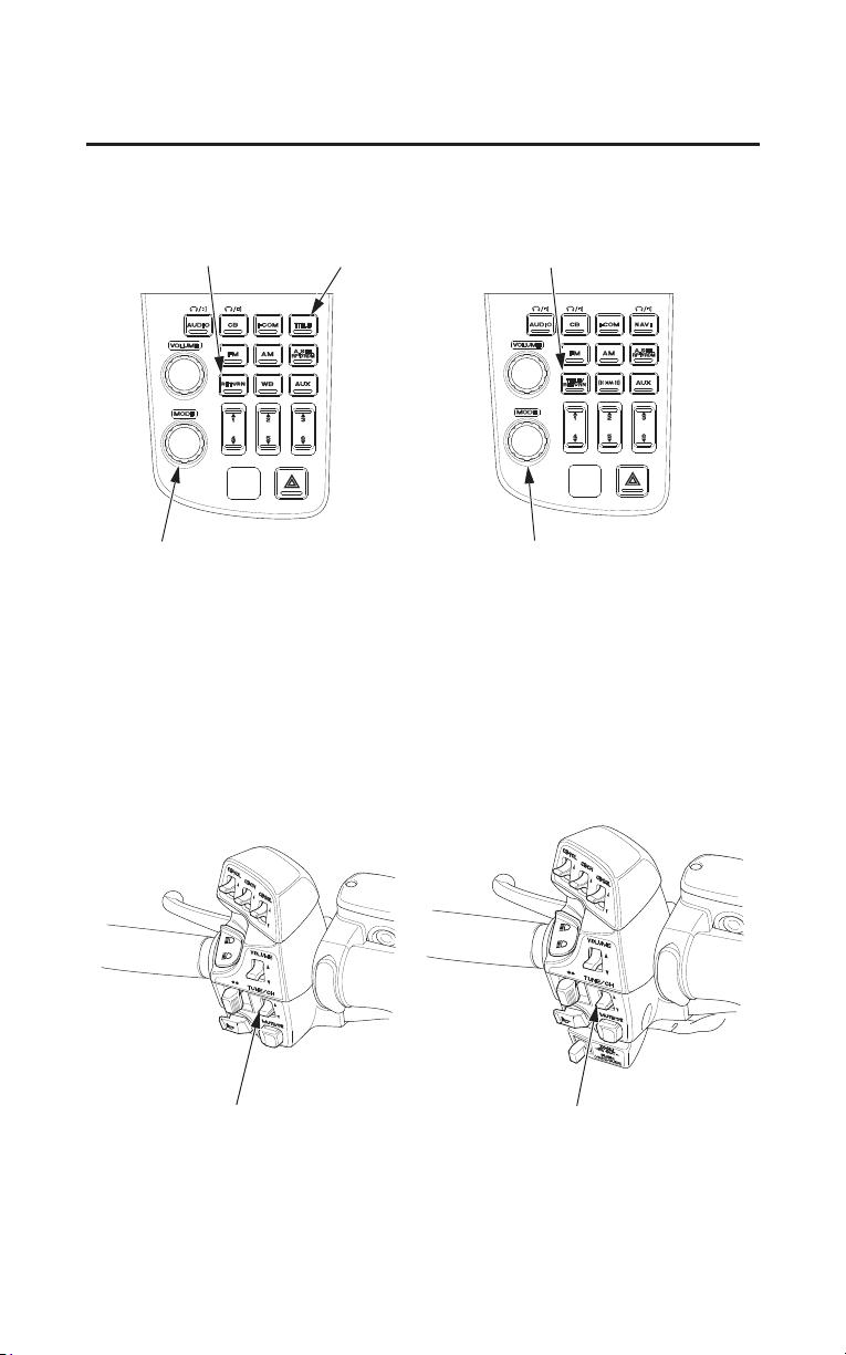
Audio Systems
141
iPod
®
/USB Flash Drive
You can also change or select files and folders by using TUNE/CH lever while a
USB flash drive is playing files.
Push the TUNE/CH lever up to change to the next file.
Push the TUNE/CH lever down to change to the previous file.
To change the folders, push and hold the TUNE/CH lever up or down.
TUNE/CH lever
(Models not equipped with
Navigation System)
(Models equipped with
Navigation System)
TUNE/CH lever
RETURN button
(Models not equipped with
Navigation System)
(Models equipped with
Navigation System)
TITLE/RETURN button
MODE knob/button MODE knob/button
TITLE button
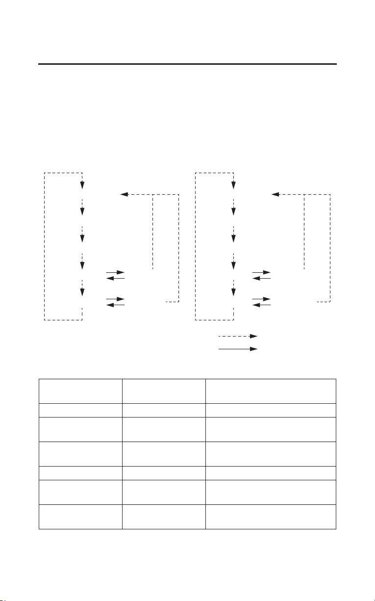
142
Audio Systems
iPod
®
/USB Flash Drive
You can select repeat and random play modes when playing a file.
To select a play mode
Push the A.SEL RPT/RDM button until the desired play mode is displayed.
The display changes as follows each time the A.SEL RPT/RDM button is
pushed.
NO DISPLAY
F. RP T
F.RDM
A.RDM
FT.RPT
RT.RPT
(Models not equipped with
Navigation System)
(Models equipped with
Navigation System)
Push the A.SEL RPT/RDM button:
Push and hold the A.SEL RPT/RDM button:
T.R PT
NO DISPLAY
F. RP T
F.RDM
RDM
F.RDM
RPT
RDM RPT
RPT
T.RP T RPT
F. RP T F. RPT
F.RDM F.RDM
A.RDM RDM
FT.RPT
F.RDM
RPT
RT.RPT RDM RPT
Play Mode Menu Items
Not equipped with
Navigation
Equipped with
Navigation
Function
Repeats the current file.
Repeats all files in the current
folder.
Plays all files in the current folder
in random order.
Plays all files in random order.
Repeats current file in F.RDM
play mode.
Repeats current file in A.RDM/
RDM play
mode.

Audio Systems
143
iPod
®
/USB Flash Drive
USB Error Messages
(Models not equipped with Navigation System)
If an error occurs while playing an iPod
®
or USB flash drive, you may see the
following error messages. If you cannot clear the error message, contact a
dealer.
BAD USB DEVICE
CHECK USB
USB ERROR
NO SONG
UNSUPPORTED
UNPLAYABLE
(Models equipped with Navigation System)
If an error occurs while playing an iPod
®
or USB flash drive, you may see the
error message. To clear the error message, turn the ignition switch off once and
turn it on again, and/or reconnect the device.
If you cannot clear the error message, contact a dealer.
Error Message Cause Solution
Problem with the
device or USB
cable.
Turn the ignition switch off
once and turn it on again.
Reconnect the device.
Do not reconnect the device
that caused the error.
Problem with the
device or USB
cable.
Turn the ignition switch off
once and turn it on again.
Reconnect the device.
Do not reconnect the device
that caused the error.
Problem with the
device or USB
cable.
Turn the ignition switch off
once and turn it on again.
Reconnect the device.
Do not reconnect the device
that caused the error.
No files in device. Check the files in device.
Use of unsupported
device.
Update the firmware.
Use supported device.
Problem with the
audio unit or
device.
Turn the ignition switch off
once and turn it on again.
Reconnect the device.
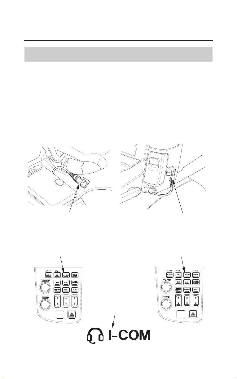
144
Audio Systems
Intercom (I-COM) System
System Control
Some local governments prohibit the use of a headset by the operator of a motor
vehicle. Always obey applicable laws and regulations.
The intercom system may be used to communicate with your passenger. (If you
want to use this system, you must have headsets.)
• To turn the system on — push the I-COM button. (I-COM appears on the
display.)
• To turn the system off — push and hold the I-COM button. (I-COM
disappears.)
front headset terminal
rear headset terminal
I-COM button
I-COM mode indicator
I-COM button
(Models not equipped with
Navigation System)
(Models equipped with
Navigation System)
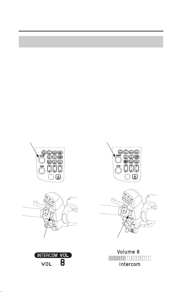
Audio Systems
145
Intercom (I-COM) System
VOLUME Control
To select the Volume control, push the VOLUME knob/button until
‘‘INTERCOM VOL’’ (‘‘Intercom’’) is displayed (page 98). Then, within 5
seconds, change the volume control.
• To increase the volume — push the VOLUME lever up or turn the
VOLUME knob/button clockwise.
• To decrease the volume —push the VOLUME lever down or turn the
VOLUME knob/button counterclockwise.
To increase or decrease the volume rapidly ï push the VOLUME lever up or
down and hold it down.
(VOLUME level range : from 0 to 20)
VOLUME knob/button
(Models not equipped with
Navigation System)
(Models equipped with
Navigation System)
VOLUME knob/button
VOLUME leverVOLUME lever
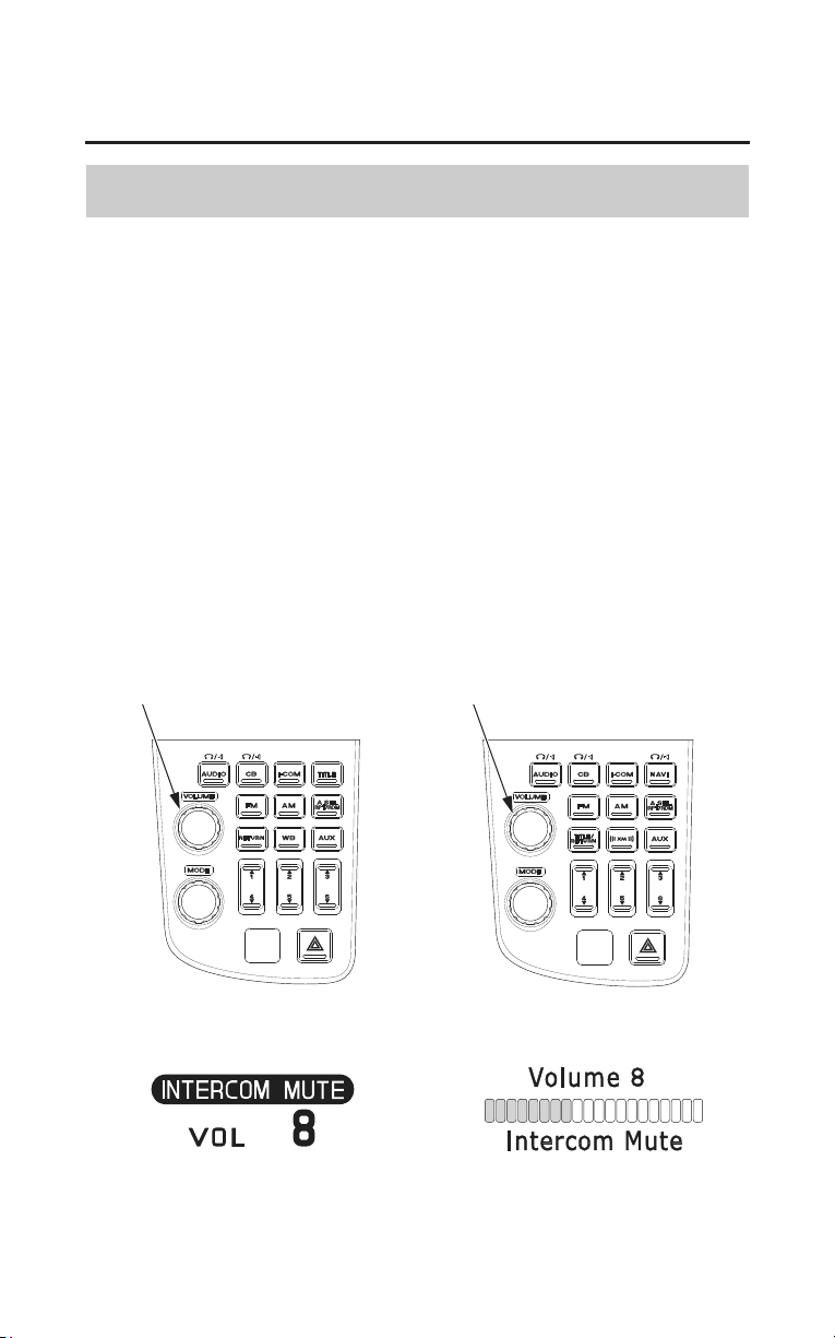
146
Audio Systems
Intercom (I-COM) System
Intercom Muting
The intercom mute system automatically lowers (does not silence) the music/
program volume when you speak through the intercom.
The sensitivity of the intercom microphone to your voice or ambient sound sets
the level at which the intercom system mutes the music/program volume.
To adjust this system push the VOLUME knob/button until ‘‘INTERCOM
MUTE’’ (‘‘Intercom Mute’’) is displayed (page 98).
• To increase microphone sensitivity — turn the VOLUME knob/button
clockwise.
• To decrease microphone sensitivity — turn the VOLUME knob/button
counterclockwise. (Intercom Mute
control range: from 0 to 20)
VOLUME knob/button
(Models not equipped with
Navigation System)
(Models equipped with
Navigation System)
VOLUME knob/button
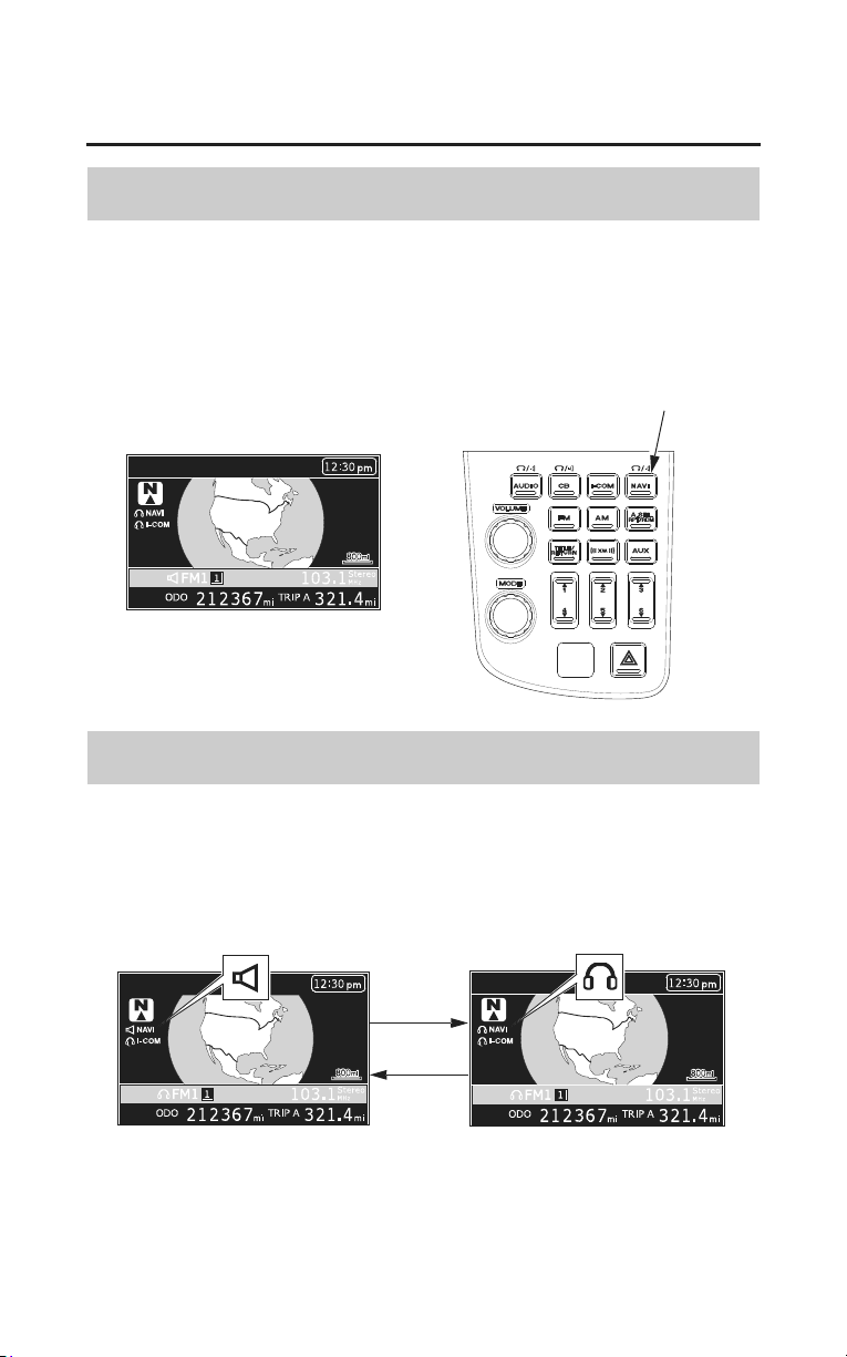
Audio Systems
147
Navigation System
System Control
To turn the Navi voice on with the Navigation System turned off ï push theࠉ
NAVI button.
To turn the Navi voice off with the Navigation System turned on ï push and
hold the NAVI button.
NAVI button
Switch Output
When the navigation voice guidance is turned on, you can switch its output
between Speaker and Headset (optional equipment).
• Push the NAVI button switches output.
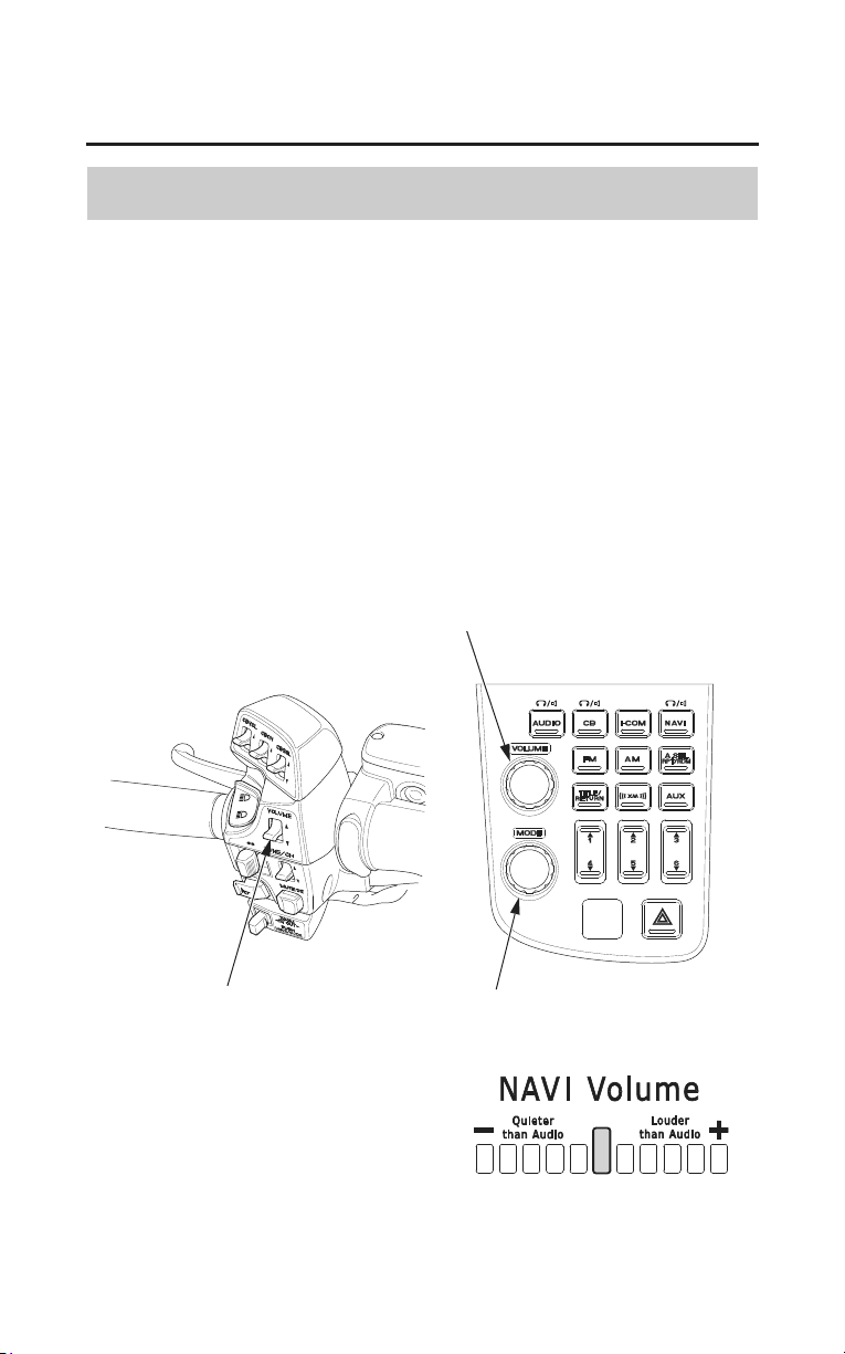
148
Audio Systems
Navigation System
Navi Volume Control
To select the volume control, push the VOLUME knob/button until ‘‘NAVI
VOL’’ is displayed (page 98). Then, within the 5 seconds, change the navigation
volume control.
To make the Navi volume louder than the audio volume – push the VOLUME
lever up or turn the VOLUME knob/button clockwise.
To make the Navi volume quieter than the audio volume – push the VOLUME
lever down or turn the VOLUME knob/button counterclockwise.
To increase or decrease the volume rapidly – push the VOLUME lever up or
down and hold it down.
(NAVI VOLUME level ranges: from 5 down to ï5)
MODE knob/button
VOLUME lever
VOLUME knob/button

Servicing Your Honda
149
Servicing Your Honda
To help keep your motorcycle in good shape, this section includes a
Maintenance Schedule for required service, a list of periodic checks you should
perform at least once a month, and step-by-step instructions for specific
maintenance tasks. You’ll also find important safety precautions, information on
fuels and oils, and tips for keeping your Honda looking great.
For information about the exhaust emission and noise emission requirements of
the U.S. Environmental Protection Agency (EPA), the California Air Resources
Board (CARB), and Environment Canada (EC), see page 263.
For information about replacing fuses, see page 244.
USA only
Maintenance, replacement or repair of the emission control devices and
systems
may be performed by any motorcycle repair establishment or
individual using parts that are ‘‘certified’’ to EPA standards.
Before You Service Your Honda
The Importance of Maintenance .....
................................................................152
Maintenance Safety......................................................................................... 153
Important Safety Precautions...................................................................... 154
Periodic Maintenance...................................................................................... 155
Maintenance Schedule .................................................................................... 156
Maintenance Record........................................................................................ 160
(cont’d)

150
Servicing Your Honda
Servicing Your Honda
Service Preparations
Maintenance Component Locations................................................................ 161
Tool Kit (Canada only).................................................................................... 164
Owner’s Manual Storage................................................................................. 165
Cover Removal................................................................................................ 166
Clip Removal .................................................................................................. 171
Service Procedures
Fluids & Filters
Fuel.................................................................................................................. 172
Engine Oil & Filter.......................................................................................... 175
Coolant ........................................................................................................... 182
Crankcase Breather ........................................................................................ 185
Final Drive Oil ............................................................................................... 186
Engine
Clutch System ................................................................................................ 188
Spark Plugs..................................................................................................... 190
Chassis
Suspension...................................................................................................... 192
Brakes............................................................................................................. 196
Tires................................................................................................................ 201
Side Stand....................................................................................................... 208
Electrical
Battery ............................................................................................................ 209
Appearance Care ............................................................................................ 213

Servicing Your Honda
151
Servicing Your Honda
The following table summarizes the three types of inspections and servicing
recommendations for your motorcycle. Both the pre-ride inspection and the
scheduled maintenance at the recommended intervals are necessary to assure
safe and dependable performance. The periodic checks provide additional
confidence in your motorcycle’s performance.
* more often if you ride frequently or long distances; or anytime you clean your
motorcycle
**unless you have the proper tools and service data and are mechanically
qualified
USA only
An optional tool kit may be available. Check with your dealer’s parts
department.
Type of Inspection/
Service
Refer to
page:
When Performed Who Performs
Pre-ride Inspection 47 before every ride you
Periodic Maintenance 155 monthly* you
Maintenance Schedule 156 interval on schedule your dealer**

152
Servicing Your Honda
The Importance of Maintenance
Keeping your motorcycle well-maintained is absolutely essential to your safety.
It’s also a good way to protect your investment, get maximum performance,
avoid breakdowns, and have more fun. A properly maintained motorcycle will
also help to reduce air pollution.
Remember, proper maintenance is the owner’s responsibility. Be sure to inspect
your motorcycle before each ride, perform the periodic chec
ks, and follow the
Maintenance Schedule in this section.
Improperly maintaining this
motorcycle or failing to correct a
problem before you ride can
cause a crash in which you can
be seriously hurt or killed.
Always follow the inspection and
maintenance recommendations
and schedules in this
owner’s
manual.
If your motorcycle overturns or is involved in a crash, be sure your dealer
inspects all major parts, even if you are able to make some of the repairs
yourself.
Servicing Your Honda
153
Maintenance Safety
This section includes instructions on how to perform some important
maintenance tasks. If you have basic mechanical skills, you can perform many
of these tasks with the tools provided with your motorcycle.
Other tasks that are more difficult and require special tools are best performed
by professionals. Wheel removal should normally be handled only by a Honda
technician or other qualified mechanic. Instructions are included in this manual
only to assist in emergency service.
Some of the most important safety precautions follow. However, we cannot
warn you of every conceivable hazard that can arise in performing maintenance.
Only you can decide whether or not you should perform a given task.
Failure to properly follow
maintenance instructions and
precautions can cause you to be
seriously hurt or killed.
Always follow the procedures
and precautions in this owner’s
manual.

154
Servicing Your Honda
Maintenance Safety
Important Safety Precautions
• Make sure the engine is off before you begin any maintenance or repairs.
This will help eliminate several potential hazards:
Carbon monoxide poisoning from engine exhaust. Be sure there is
adequate ventilation whenever you operate the engine.
Burns from hot motorcycle parts. Let the engine and exhaust system cool
before touching.
Injury from moving parts. Do not run the engine unless instructed to do so.
• Read the instructions before you begin, and make sure you have the tools and
skills required.
• To help prevent the motorcycle from falling over, park it on a firm, level
surface, using the center stand.
• To reduce the possibility of a fire or explosion, be careful when working
around gasoline. Use only non-flammable solvent, not gasoline, to clean
parts. Keep cigarettes, sparks, and flames away from all fuel-related parts.
Remember that your Honda dealer knows your motorcycle best and is fully
equipped to maintain and repair it. To ensure the best quality and reliability, use
only new Honda Genuine Parts or their equivalents for repair and replacement.
If you have the tools and skills required for additional maintenance jobs, you
can purchase an official Honda Service Manual (page 270).
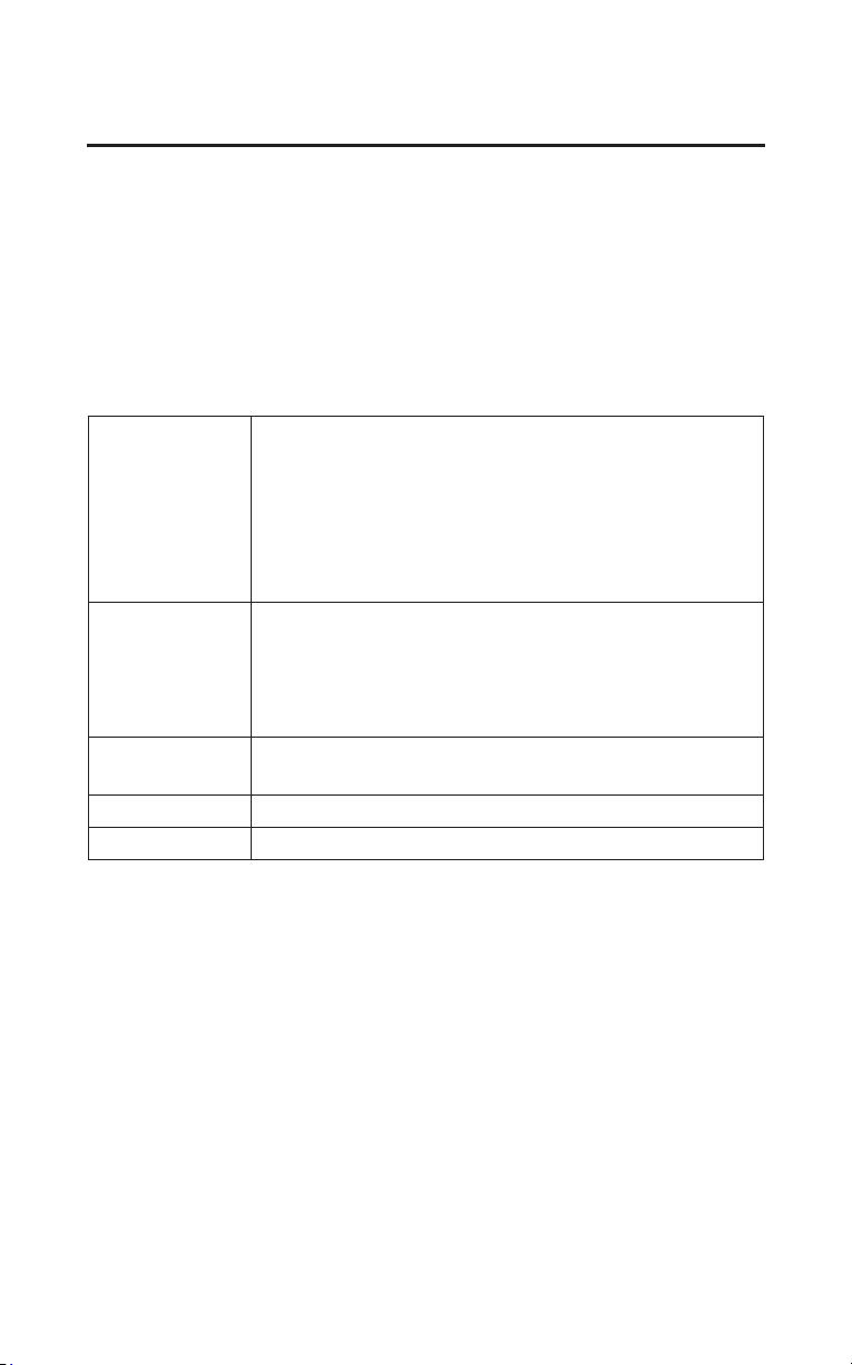
Servicing Your Honda
155
Periodic Maintenance
In addition to the regularly scheduled maintenance (page 156) and daily pre-ride
inspection (page 47), consider performing the periodic checks on the following
page at least once a month, even if you haven’t ridden your motorcycle, or as
often as once a week if you ride frequently or for long distances. It’s a good idea
to perform this maintenance any time you clean your motorcycle.
Check the odometer reading and perform any scheduled maintenance checks
that are needed (page 156). Remember, more frequent checks may be needed for
riding in severe conditions.
Tires
&
Wheels
Check the air pressure with a gauge and add air if needed
(page 202).
Examine the tread for wear (page 203).
Look closely for nails, embedded objects, cuts, and other
types of damage (page 203). Rotate the rear wheel so you
can inspect the entire surface.
Check the condition of the wheels.
Fluids Check the levels of the engine oil (page 178), coolant
(page 183), brake fluid (page 197), clutch fluid
(page 189), and final drive oil (page 186). Add the
correct fluid as necessary, and investigate the cause of
any low fluid level.
Lights Make sure the headlight, brake light, tail light, and turn
signals are working properly.
Fuses Make sure you have a full supply of spare fuses.
Nuts & Bolts Check the major fasteners and tighten as needed.

156
Servicing Your Honda
Maintenance Schedule
The required Maintenance Schedule that follows specifies how often you should
have your motorcycle serviced, and what things need attention. It is essential to
have your motorcycle serviced as scheduled to maintain safe, dependable
performance and proper emission control.
The service intervals in this Maintenance Schedule are based on average riding
co
nditions. Some items will need more frequent service if you ride in unusually
wet or dusty areas or at full throttle. Consult your dealer for recommendations
applicable to your individual needs and use.
Some items in the Maintenance Schedule can be performed with basic
mechanical skills and hand tools. Procedures for these items are provided in this
manual. Other items involve more extensive procedures and may require special
training, tools, and equipment. We recommend that you have your dealer
perform these tasks unless you have advanced mechanical skills and the
required tools and equipment. Procedures for such items in this schedule are
provided in an official Honda Service Manual available for purchase (page
270).

Servicing Your Honda
157
Maintenance Schedule
If you do not feel capable of performing a given task or need assistance,
remember that your Honda dealer knows your motorcycle best and is fully
equipped to maintain and repair it. If you decide to do your own maintenance,
use only Honda Genuine Parts or their equivalents for repair or replacement to
ensure the best quality and reliability.
Perform the pre-ride inspection (page 47) and owner maintenance (page 158) at
each scheduled maintenance period.
The following items require some mechanical knowledge. Certain items
(particularly
those marked * and **) may require more technical information
and tools. Consult your dealer.
* Should be serviced by your dealer, unless you have the proper tools and
service data and are mechanically qualified. Refer to the official Honda
Service Manual (page 270).
** In the interest of safety, we recommend these items be serviced only by your
dealer.
Summary of Maintenance Schedule Notes
& Procedures:
NOTES:
1. At higher odometer readings, repeat at the frequency interval established
here.
2. Service more frequently if the motorcycle is ridden in unusually wet or dusty
are
as.
3. Service more frequently if the motorcycle is ridden often at full throttle or in
the rain.
4. Service more frequently if noisy.
5. Replace every 2 years, or at indicated odometer interval, whichever comes
first. Replacement requires mechanical skill.
6. Replace at 4,000 mi (6,400 km) or 6 months, then every 8,000 mi (12,800
km) or 12 months.
Maintenance Procedures:
I: inspect and clean, adjust, lubricate,
or replace, if necessary
C: clean
A: adjust
L: lubricate
R: replace
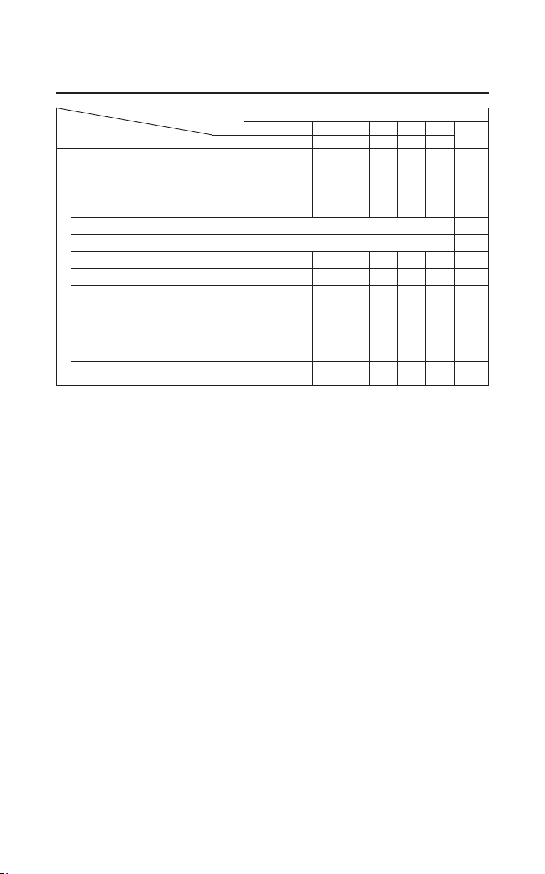
FREQUENCY ODOMETER READING (Note 1)
×
1,000 mi
4 8 12 16 20 24
Refer
to page
ITEMS NOTE
×
1,000 km
6.4 12.8 19.2 25.6 32.0 38.4
EMISSIONS-RELATED ITEMS
*
FUEL LINE I I I –
*
THROTTLE OPERATION I I I –
*
AIR CLEANER 2 R R –
CRANKCASE BREATHER 3 C C C C C C 185
SPARK PLUGS EVERY 16,000 mi (25,600 km) R 190
*
VALVE CLEARANCE 4 EVERY 32,000 mi (51,200 km) I –
ENGINE OIL 6 R R R 175
ENGINE OIL FILTER R R R 179
*
ENGINE IDLE SPEED I I I –
RADIATOR COOLANT 5 I I R 182
*
COOLING SYSTEM I I I –
*
SECONDARY AIR
SUPPLY SYSTEM
III–
*
EVAPORATIVE EMISSION
CONTROL SYSTEM
II–
158
Servicing Your Honda
Maintenance Schedule
* Should be serviced by your dealer, unless you have the proper tools and service data and are
mechanically qualified. Refer to the official Honda Service Manual (page 270).
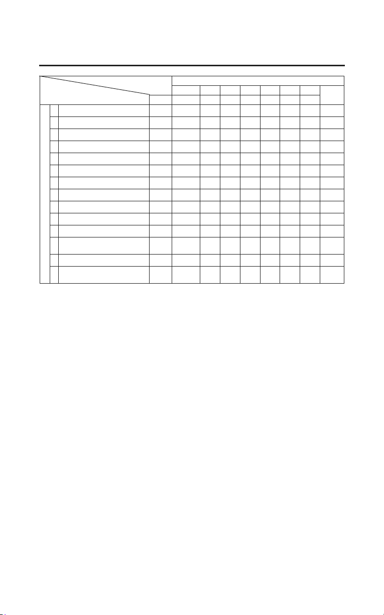
FREQUENCY ODOMETER READING (Note 1)
×
1,000 mi
4 8 12 16 20 24
Refer
to page
ITEMS NOTE
×
1,000 km
6.4 12.8 19.2 25.6 32.0 38.4
NON-EMISSIONS-RELATED ITEMS
FINAL DRIVE OIL I I R 186
BRAKE FLUID 5 I I R I I R 197
BRAKE PADS WEAR I I I I I I 199
BRAKE SYSTEM I I I 200
*
BRAKE LIGHT SWITCH I I I –
*
HEADLIGHT AIM I I I –
CLUTCH SYSTEM I I I 188
CLUTCH FLUID 5 I I R I I R 189
*
REVERSE OPERATION I I I –
SIDE STAND I I I 208
*
SUSPENSION I I I –
*
NUTS, BOLTS,
FASTENERS
III–
**
WHEELS/TIRES I I I –
**
STEERING HEAD
BEARINGS
III–
Servicing Your Honda
159
Maintenance Schedule
* Should be serviced by your dealer, unless you have the proper tools and service data and
are mechanically qualified. Refer to the official Honda Service Manual (page 270).
** In the interest of safety, we recommend these items be serviced only by your dealer.

160
Servicing Your Honda
Maintenance Record
Keeping an accurate maintenance record will help ensure that your motorcycle
is properly maintained. Retain detailed receipts to verify the maintenance was
performed. If the motorcycle is sold, these receipts should be transferred with
the motorcycle to the new owner. Make sure whoever performs the maintenance
completes this record. All scheduled maintenance is considered a normal owner
operating cost and will be charged for by your dealer. Use the space under Notes
to record anything you want to remind yourself about or mention to your dealer.
Miles
(km)
Odometer Date Performed By: Notes
4,000
(6,400)
8,000
(12,800)
12,000
(19,200)
16,000
(25,600)
20,000
(32,000)
24,000
(38,400)
28,000
(44,800)
32,000
(51,200)
36,000
(57,600)
40,000
(64,000)
44,000
(70,400)
48,000
(76,800)
52,000
(83,200)
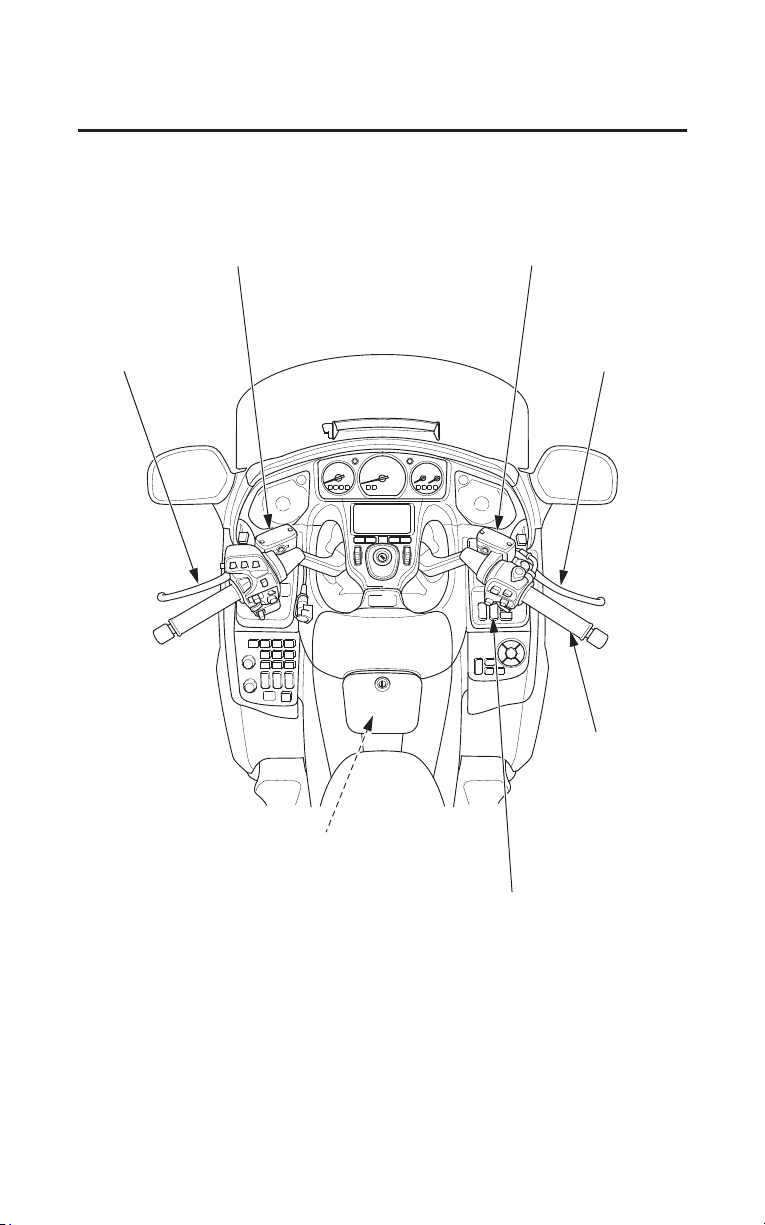
clutch fluid reservoir
front brake lever
throttle grip
fuel fill cap
front brake fluid reservoir
clutch lever
rear suspension spring pre-load
adjustment switch
Servicing Your Honda
161
Maintenance Component Locations
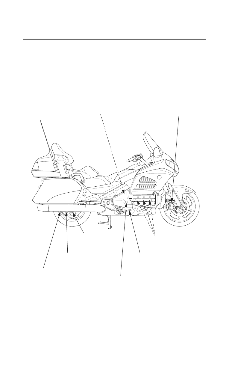
rear brake fluid reservoir
front brake caliper
spark plugs
engine oil fill cap/dipstick
rear brake caliper
rear brake pedal
final drive gear
oil drain bolt
final drive gear oil fill cap
162
Servicing Your Honda
Maintenance Component Locations
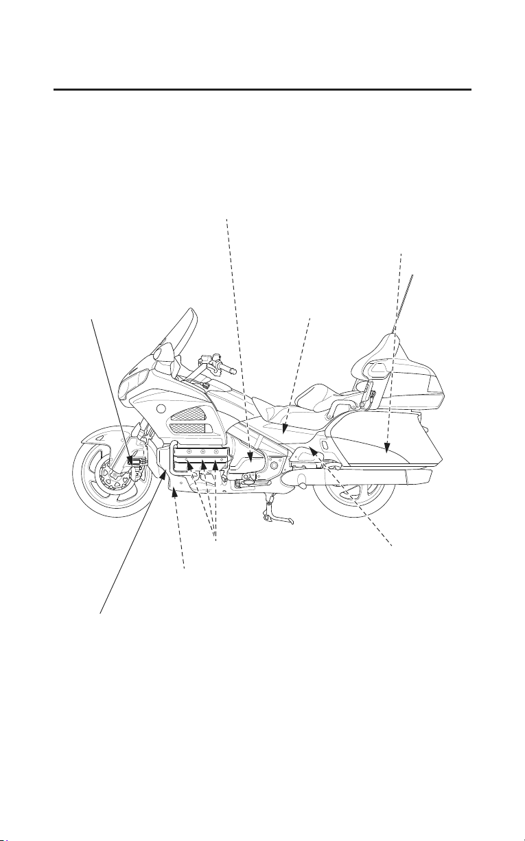
coolant reserve tank cap
front brake caliper
owner’s manual
tool kit (Canada only)
spark plugs
fuse box
main fuse (A, B)
engine oil filter
engine oil drain bolt
battery
crankcase breather tube
Servicing Your Honda
163
Maintenance Component Locations
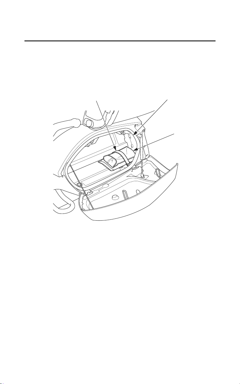
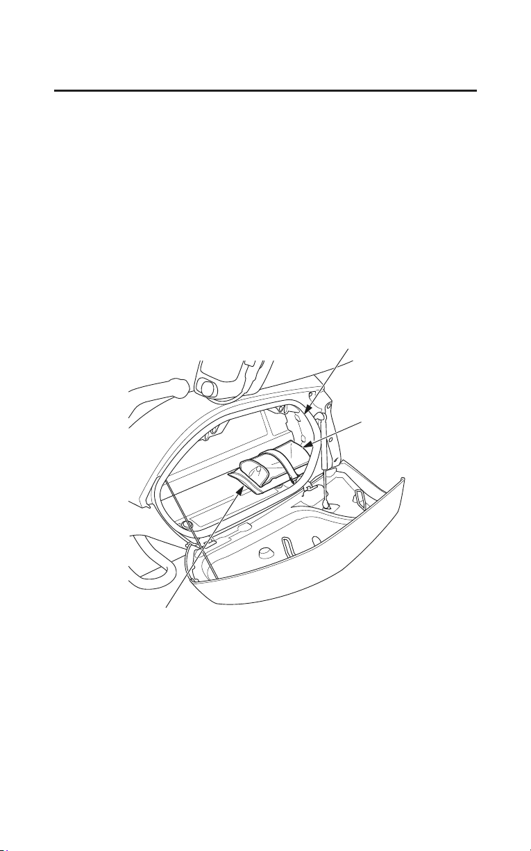
Servicing Your Honda
165
Owner’s Manual Storage
Your motorcycle provides storage for the owner’s manual so you’ll have it with
you for easy reference. Store your owner’s manual (and other documents) in the
plastic storage bag in the left saddlebag (page 52).
For models equipped with Navigation System:
Store your Navigation System Manual with your owner’s manual.
For models equipped with Airbag:
Store your Owner’s Manual Airbag Supplement and Navigation System Manual
with your owner
’s manual.
Be careful not to flood this area when washing your motorcycle.
LEFT SIDE
owner’s manual
left saddlebag
tool kit
(Canada only)
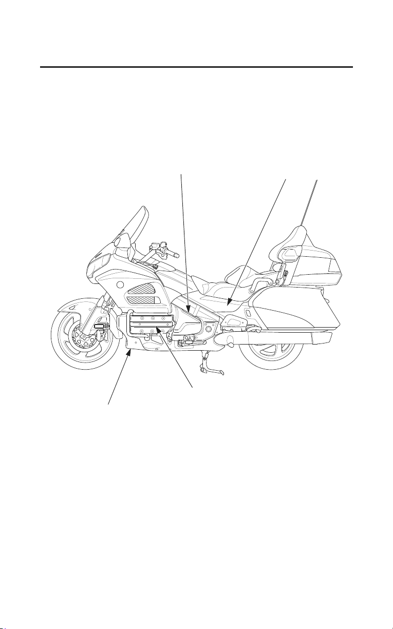
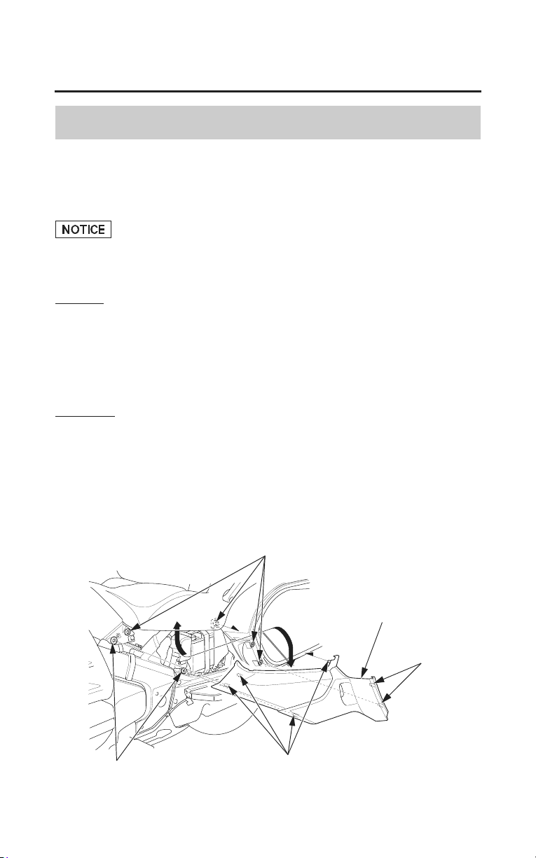
Servicing Your Honda
167
Cover Removal
Side Cover Removal
Refer to Safety Precautions on page 154.
The left side cover must be removed for battery and fuse maintenance.
Failure to use extreme care removing or installing the side covers may damage
the side cover prongs.
Removal
1. Open the saddlebag (page 53).
2. Pull the side cover out until the prongs A are clear of the frame grommets.
3. Carefully pull the side cover out until the prongs B are clear of the frame
grommets.
4. Carefully remove the side cover.
Installation
1. Insert the top edge of the side cover under the seat.
2. Position the side cover so the prongs on the inside of the cover are lined up
above their securing grommets.
3. Push the cover in place.
4. Close the saddlebag.
LEFT SIDE
grommets
side cover
grommets
prongs A
prongs B
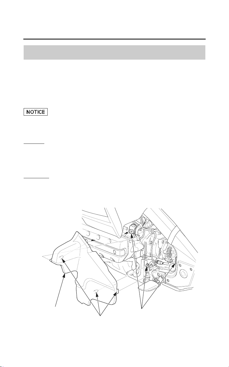
168
Servicing Your Honda
Cover Removal
Engine Side Cover Removal
Refer to Safety Precautions on page 154.
The left engine side cover must be removed for coolant maintenance.
The right engine side cover must be removed for engine oil and rear brake fluid
maintenance.
Failure to use extreme care removing or installing the engine side covers may
damage the engine side cover prongs.
Removal
1. Carefully pull the rear of the engine side cover out until the prongs are clear
of their securing grommets.
2. Remove the engine side cover backward.
Installation
• Installation can be done in the reverse order of removal.
LEFT SIDE
grommets
engine side cover
prongs
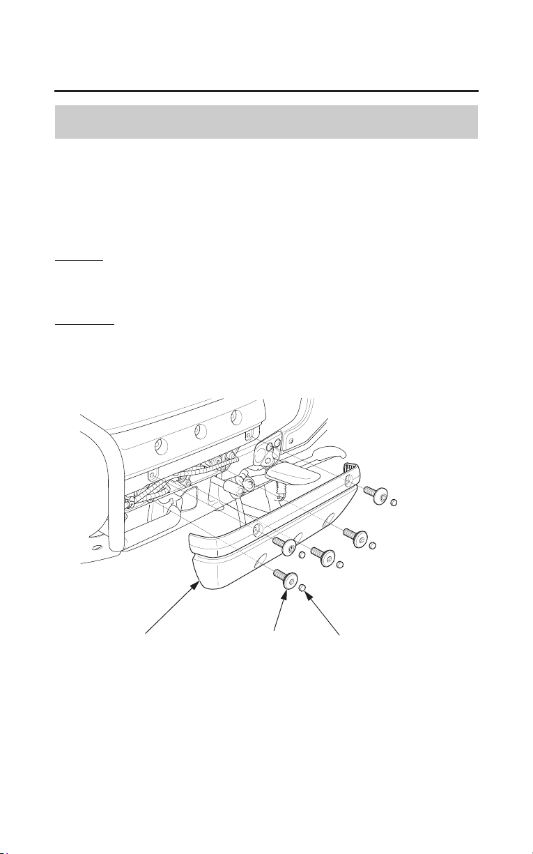
Servicing Your Honda
169
Cover Removal
Cylinder Head Side Cover Removal
Refer to Safety Precautions on page 154.
Both cylinder head side covers must be removed for spark plug maintenance.
The left cylinder head side cover must be removed for crankcase breather
maintenance.
Removal
1. Remove the rubber plugs.
2. Remove the bolts.
Installation
• Installation can be done in the reverse order of removal.
LEFT SIDE
cylinder head side cover
bolt
rubber plug
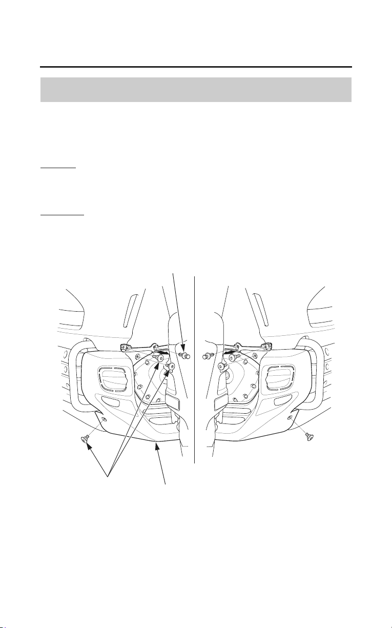
170
Servicing Your Honda
Cover Removal
Front Lower Cover Removal
Refer to Safety Precautions on page 154.
The front lower cover must be removed for engine oil maintenance.
Removal
1. Remove the clips.
2. Remove the bolts.
Installation
Installation can be done in the reverse order of removal.
FRONT
front lower cover
bolts
clip
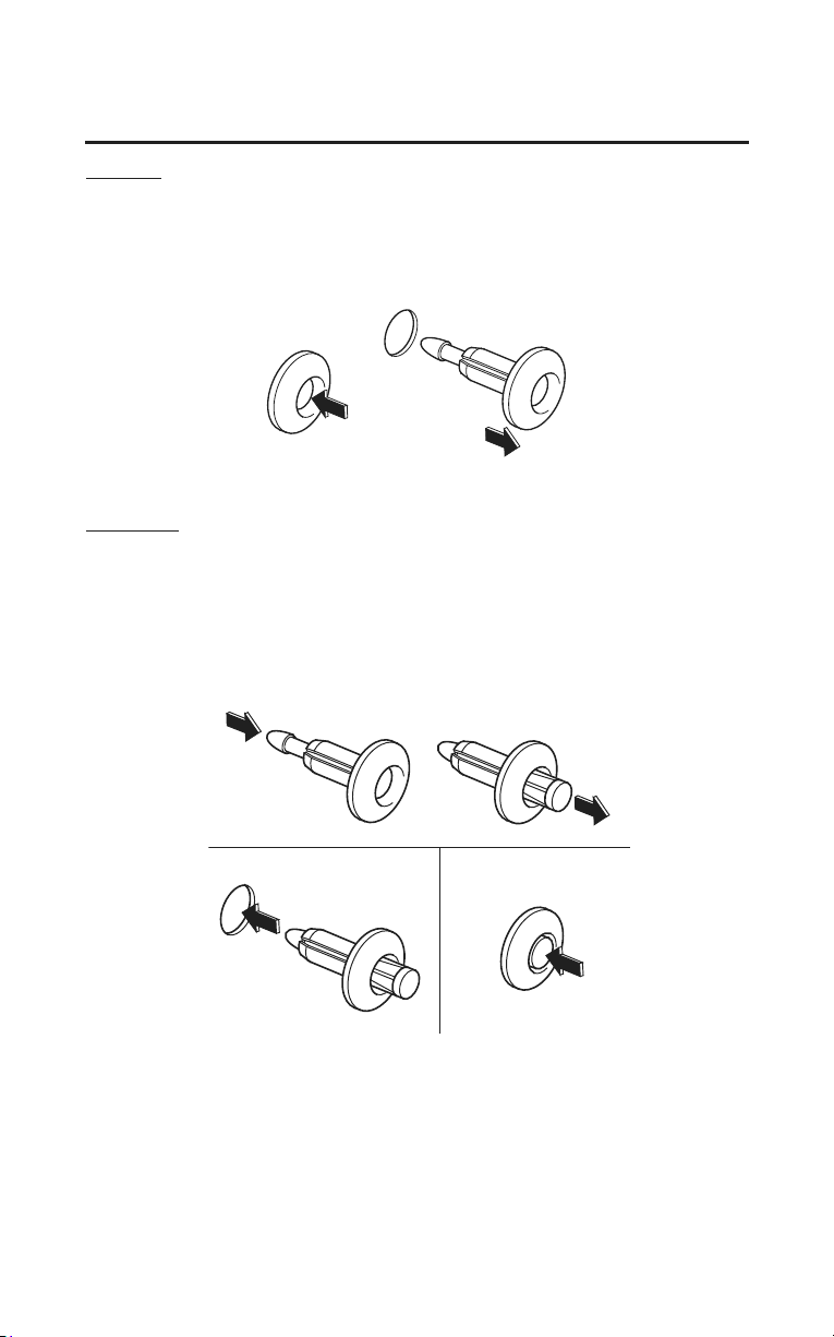
Servicing Your Honda
171
Clip Removal
Removal
1. Press down on the center pin to release the lock.
2. Pull the clip out of the hole.
1. 2.
Installation
1. Push the bottom of the pin.
2. Insert the clip into the hole.
3. Lightly press down on the center pin to lock the clip.
1.
2. 3.

172
Servicing Your Honda
Fuel
Refer to Safety Precautions on page 154.
Fuel Recommendation
type unleaded
pump octane number 86 (or higher)
Use only unleaded fuel in your Honda. Use of leaded fuel will damage the
ca
talytic converter(s). If you ride your Honda in a country where leaded fuel
might be available, use precautions to use only unleaded fuel.
Your engine is designed to use any unleaded gasoline that has a pump octane
number of 86 or higher. Gasoline pumps at service stations normally display the
pump
octane number. For information on the use of oxygenated fuels,
see page 268.
Use of lower octane gasoline can cause persistent ‘‘pinging’’ or ‘‘spark knock’’
(a loud rapping noise) which, if severe, can lead to engine damage. Light
pinging experienced while operating under a heavy load, such as climbing a hill,
is no cause for concern.
If pinging or spark knock occurs at a steady engine speed under normal load,
ch
ange brands of gasoline. If pinging or spark knock persists, consult your
dealer.
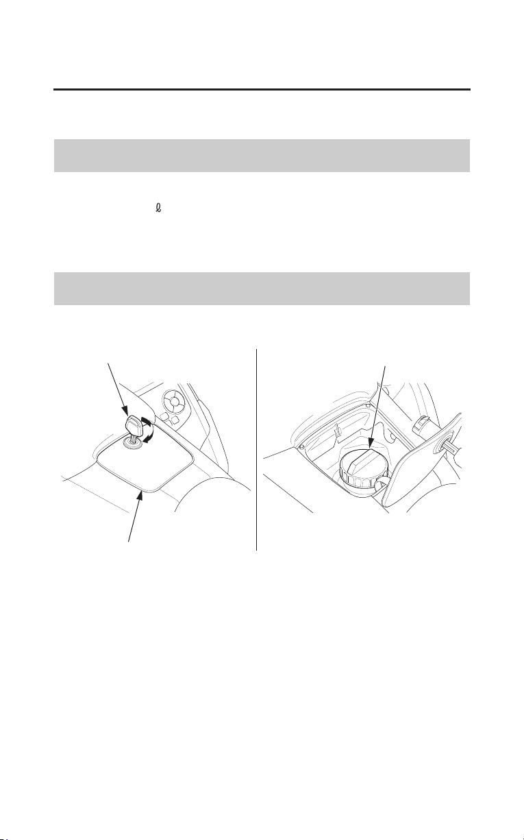
Servicing Your Honda
173
Fuel
Never use stale or contaminated gasoline or an oil/gasoline mixture. Avoid
getting dirt, dust, or water in the fuel tank.
Fuel Capacity
Fuel tank capacity, including reserve:
6.6 US gal (25
)
The tank should be refilled as soon as possible when the fuel gauge needle
enters the red band.
Refueling Procedure
Refer to Safety Precautions on page 154.
ignition key
fuel fill cap
fuel fill compartment
1. Insert the ignition key in the fuel fill compartment and turn it clockwise.
2. Open the fuel fill compartment.
3. Turn the fuel fill cap counterclockwise and remove it.
(cont’d)
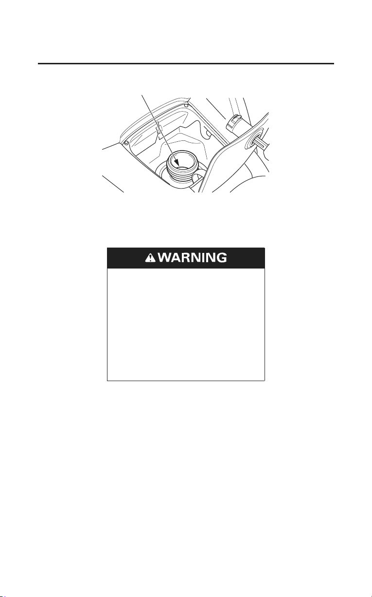
filler neck
174
Servicing Your Honda
Fuel
4. Add fuel until the level reaches the bottom of the filler neck.
Avoid overfilling the tank. There should be no fuel in the filler neck.
Gasoline is highly flammable
and explosive. You can be
burned or seriously injured when
handling fuel.
• Stop the engine and keep
heat, sparks and flame away.
• Handle fuel only outdoors.
• Wipe up spills immediately.
5. After refueling, be sure to tighten the fuel fill cap firmly by turning it
clockwise until it clicks.
6. Close the fuel fill compartment.
7. Remove the key from the fuel fill compartment.

Servicing Your Honda
175
Engine Oil & Filter
Engine oil quality is a major factor that affects both the performance and the
service life of the engine.
Using the proper oil (page 176) and filter, and regularly checking, adding, and
changing oil will help extend your engine’s life. Even the best oil wears out.
Changing oil helps get rid of dirt and deposits in the engine. Operating the
engine with old or dirty oil can damage your engine. Running the engine with
insufficient oil can cause serious damage to the engine and transmission.
Change the engine oil as specified in the maintenance schedule on page 158.
When running in very dusty conditions, oil changes should be performed more
frequently than specified
in the maintenance schedule.
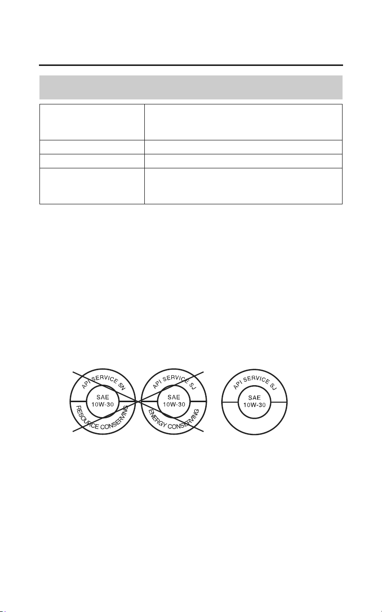
176
Servicing Your Honda
Engine Oil & Filter
Oil Recommendation
API classification SG or higher except oils labeled as energy
conserving or resource conserving on the
circular API service label
viscosity (weight) SAE 10W-30
JASO T 903 standard MA
suggested oil* Pro Honda GN4 4-stroke oil (USA &
Canada), or Honda 4-stroke oil, or an
equivalent motorcycle oil.
* Suggested oils are equal in performance to SJ oils that are not labeled as
energy conserving or resource conserving on the circular API service label.
• Your motorcycle does not need oil additives. Use the recommended oil.
• Do not use oils with graphite or molybdenum additives. They may adversely
affect clutch operation.
• Do not use API SH or higher oils displaying a circular API ‘‘energy
conserving’’ or ‘‘resource conserving’’ service label on the container. They
may affect lubrication and clutch performance.
NOT RECOMMENDED OK
• Do not use non-detergent, vegetable, or castor based racing oils.
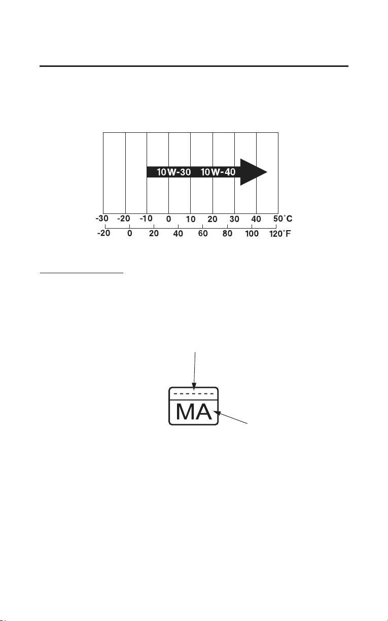
Servicing Your Honda
177
Engine Oil & Filter
Other viscosities shown in the following chart may be used when the average
temperature in your riding area is within the indicated range.
JASO T 903 standard
The JASO T 903 standard is an index for engine oils for 4-stroke motorcycle
engines.
There are two classes: MA and MB.
Oil conforming to the standard is labeled on the oil container. For example, the
following label shows the MA classification.
oil code
oil classification
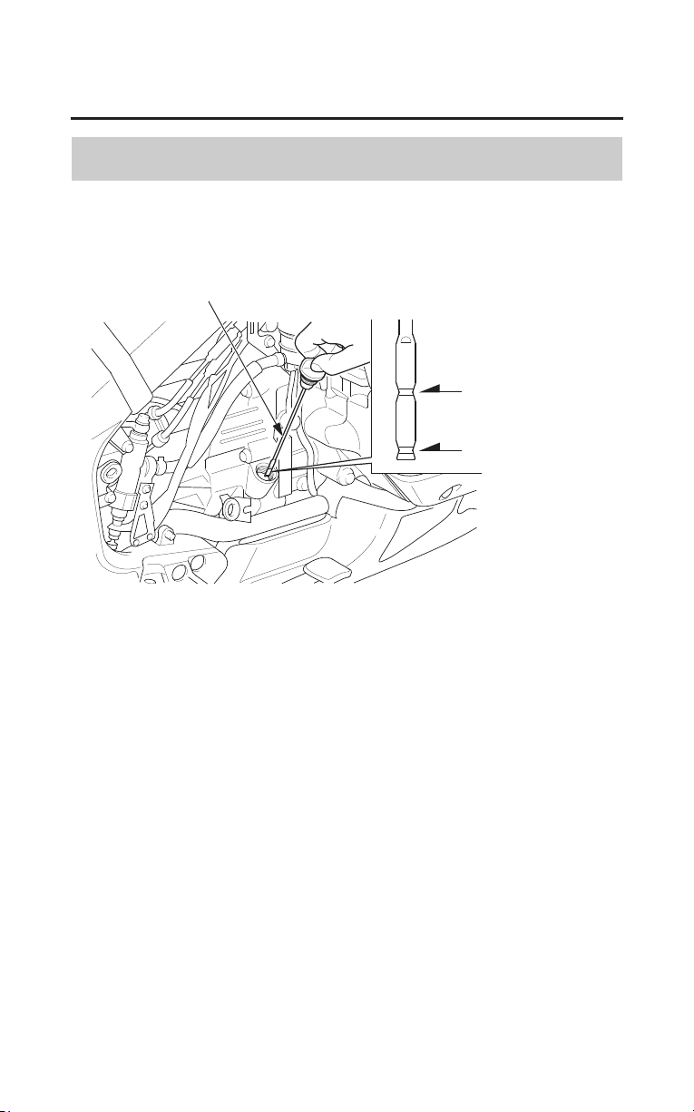
178
Servicing Your Honda
Engine Oil & Filter
Checking & Adding Oil
Refer to Safety Precautions on page 154.
RIGHT SIDE
upper level mark
oil fill cap/dipstick
lower level mark
1. Park your motorcycle on its center stand on a firm, level surface.
2. Remove the right engine side cover (page 168).
3. Start the engine and let it idle for 3 – 5 minutes. Make sure the low oil
pressure indicator goes off. If the indicator remains on, stop the engine
immediately.
4. Stop the engine and wait 2 – 3 minutes.
5. Remove the oil fill cap/dipstick and wipe it clean.
6. Insert the oil fill cap/dipstick until it seats, but don’t screw it in.
7. Remove the oil fill cap/dipstick and check the oil level.
• If the oil is at or near the upper level mark — you do not have to add oil.
• If the oil is below or near the lower level mark — add the recommended
oil until it reaches the upper level mark. (Do not overfill.)
8. Reinstall the oil fill cap/dipstick.
9. Reinstall the right engine side cover.
10. Check for oil leaks.
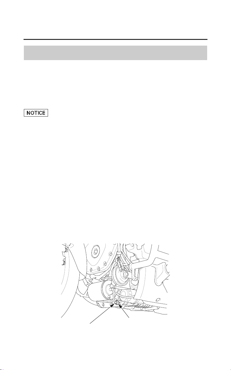
Servicing Your Honda
179
Engine Oil & Filter
Changing Engine Oil & Filter
Refer to Safety Precautions on page 154.
Your motorcycle’s oil filter has very specific performance requirements. Use a
new Honda Genuine oil filter or a filter of equal quality specified for your
model.
Using the wrong oil filter may result in leaks or engine damage.
This procedure requires mechanical skill and professional tools such as a torque
wrench and oil filter wrench, as well as a means for disposing of the drained
fluid (page 223). If you do not have the skills or the tools, see your dealer.
Drain the Engine Oil:
1. Park your motorcycle on its center stand on a firm, level surface.
2. If the engine is cold, start it and let it idle for 3 – 5 minutes. Turn the engine
off. Wait 2 – 3 minutes for the oil to settle.
3. Remove the front lower cover (page 170).
4. Place a drain pan under the engine oil drain bolt.
5. To drain the oil, remove the oil fill cap/dipstick, engine oil drain bolt, and
sealing washer.
FRONT, UNDER ENGINE
engine oil drain bolt
sealing washer
(cont’d)
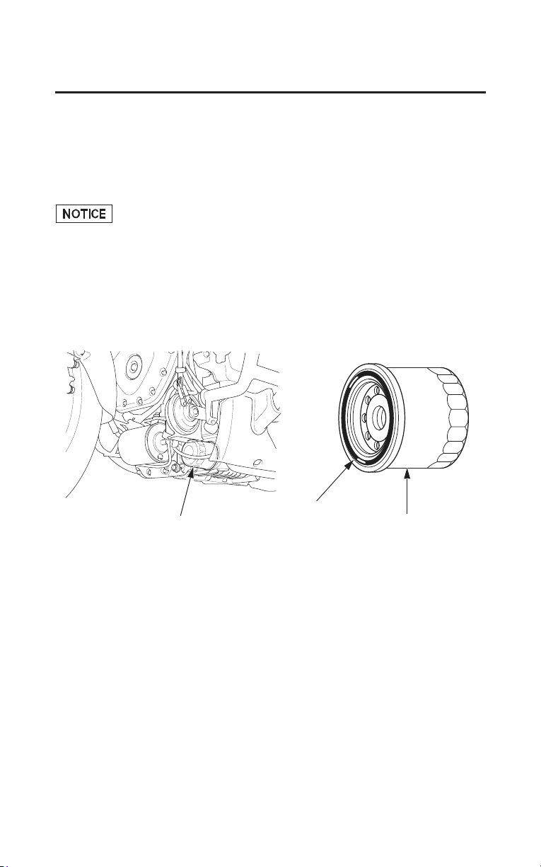
180
Servicing Your Honda
Engine Oil & Filter
Install a New Oil Filter:
6. Remove the oil filter with a filter wrench and let the remaining oil drain out.
Discard the oil filter in an approved manner (page 223).
7. Pour the drained oil into a suitable container and dispose of it in an approved
manner (page 223).
Improper disposal of drained fluids is harmful to the environment.
8. Apply a thin coat of engine oil to the rubber seal of a new oil filter.
LEFT FRONT, UNDER ENGINE
oil filter
rubber seal
oil filter
9. Install the new oil filter and tighten it by hand.
10. Using an oil filter wrench attachment and a torque wrench, tighten the new
oil filter to the specified torque:
19 lbf·ft (26 N·m, 2.7 kgf·m)
11. Check the condition of the sealing washer on the engine oil drain bolt.
Replace the washer every other time the oil is changed.
Install the engine oil drain bolt and tighten it to the specified torque:
25 lbf·ft (34 N·m, 3.5 kgf·m)

Servicing Your Honda
181
Engine Oil & Filter
Add Engine Oil:
12. Fill the crankcase with the recommended oil (page 176), approximately:
3.9 US qt (3.7
)
13. Install the oil fill cap/dipstick securely.
14. Start the engine and let it idle for 3 – 5 minutes.
15. Stop the engine and wait 2 – 3 minutes.
16. Check that the oil level is at upper level mark on the dipstick (page 178).
17. Check that there are no oil leaks.
If a torque wrench is not used for installation, see your dealer as soon as
possible to verify proper assembly.

182
Servicing Your Honda
Coolant
Your motorcycle’s liquid cooling system dissipates engine heat through the
coolant jacket that surrounds the cylinder and cylinder head.
Maintaining the coolant will allow the cooling system to work properly and
prevent freezing, overheating, and corrosion.
Coolant Recommendation
Use Pro Honda HP coolant or an equivalent high quality ethylene glycol
antifreeze containing corrosion protection inhibitors specifically recommended
for use in aluminum engines. Check the antifreeze container label.
Use only distilled water as a part of the coolant solution. Water that is high in
mineral content or salt may be harmful to the aluminum engine.
Using coolant with silicate inhibitors may cause premature wear of water pump
seals or blockage of radiator passages. Using tap water may cause engine
damage.
The factory provides a 50/50 solution of antifreeze and water in this motorcycle.
This coolant solution is recommended for most operating temperatures and
provides good corrosion protection.
Decreasing the concentration of antifreeze to less than 40% will not provide
proper corrosion protection.
Increasing the concentration of antifreeze is not recommended because it
decreases cooling system performance. Higher concentrations of antifreeze (up
to 60%) should only be used to provide additional protection against freezing.
Check the cooling system frequently during freezing weather.
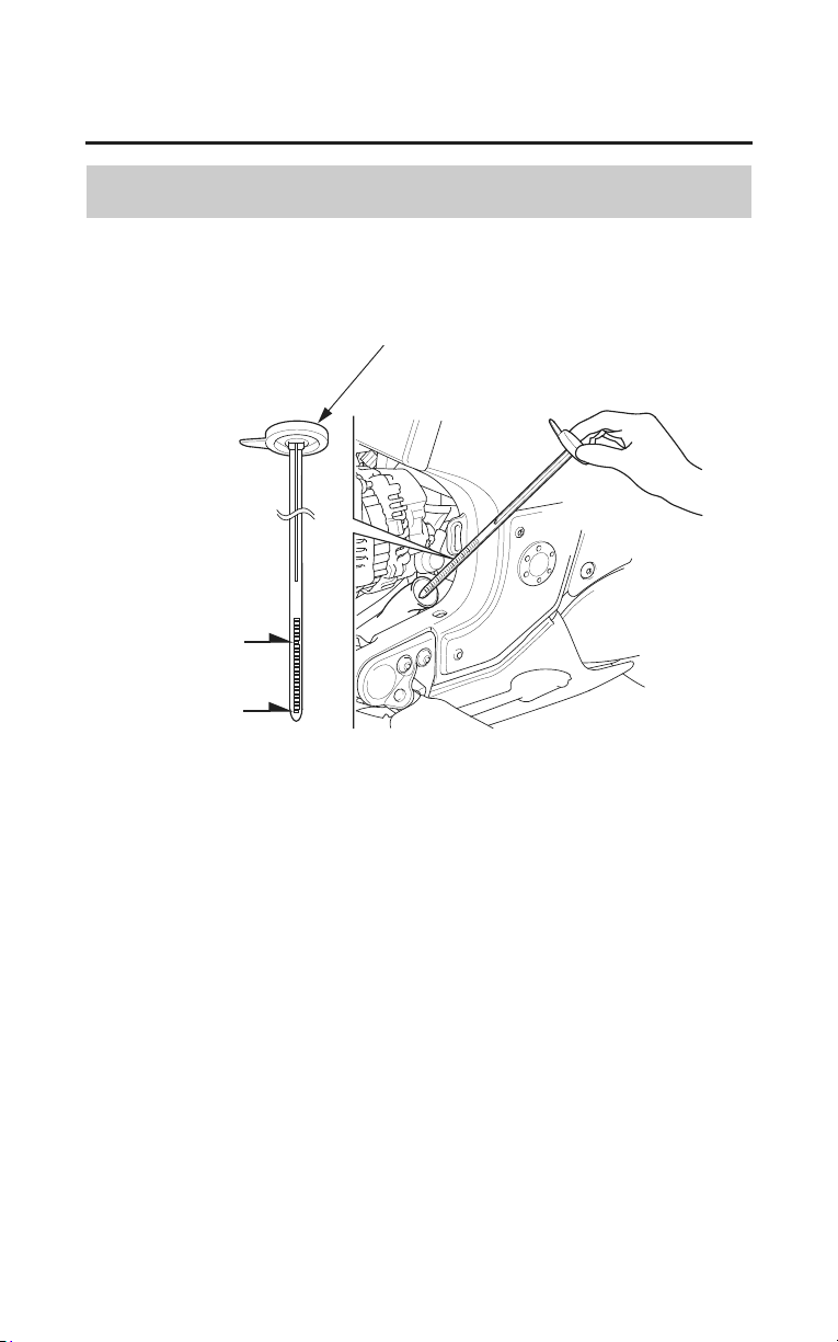
Servicing Your Honda
183
Coolant
Checking & Adding Coolant
Refer to Safety Precautions on page 154.
LEFT SIDE
upper level
lower level
reserve tank cap/dipstick
1. Remove the left engine side cover (page 168).
2. With the engine at normal operating temperature, remove the reserve tank
cap/dipstick and check the coolant level.
If the reserve tank is empty, or if coolant loss is excessive, check for leaks
and see your dealer for repair.
3. Add coolant to the reserve tank as required to bring the coolant level to the
upper level mark.
Always add coolant to the reserve tank. Do not attempt to add coolant by
removing the radiator cap.
4. Reinstall the left engine side cover.
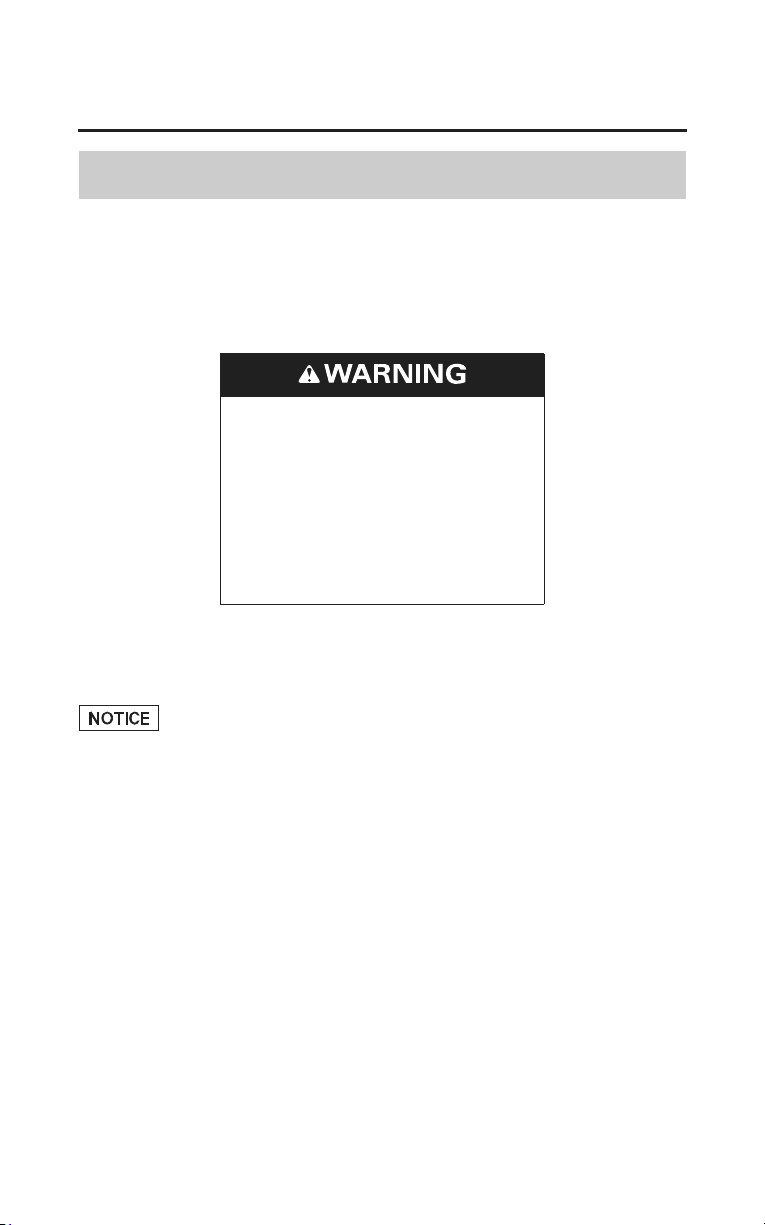
184
Servicing Your Honda
Coolant
Coolant Replacement
Refer to Safety Precautions on page 154.
Coolant should be replaced by your dealer, unless you have the proper tools and
service data and are mechanically qualified. Refer to the official Honda Service
Manual (page 270).
Removing the radiator cap while
the engine is hot can cause the
coolant to spray out, seriously
scalding you.
Always let the engine and
radiator cool down before
removing the radiator cap.
To properly dispose of drained coolant, refer to You & the Environment, page
223.
Improper disposal of drained fluids is harmful to the environment.
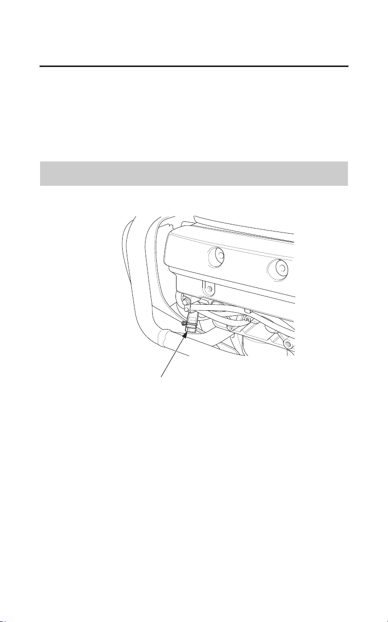
Servicing Your Honda
185
Crankcase Breather
Refer to Safety Precautions on page 154.
Service the crankcase breather more frequently if your motorcycle is ridden in
the rain or often at full throttle. Service the breather if you can see deposits in
the transparent section of the drain tube.
If the drain tube overflows, the air filter may become contaminated with engine
oil causing poor engine performance.
Draining
LEFT SIDE
crankcase breather tube plug
1. Remove the left cylinder head side cover (page 169).
2. Place a drain pan under the crankcase breather tube plug.
3. Remove the plug to drain the deposits in the tube.
4. Reinstall the crankcase breather tube plug.
5. Reinstall the left cylinder head side cover.
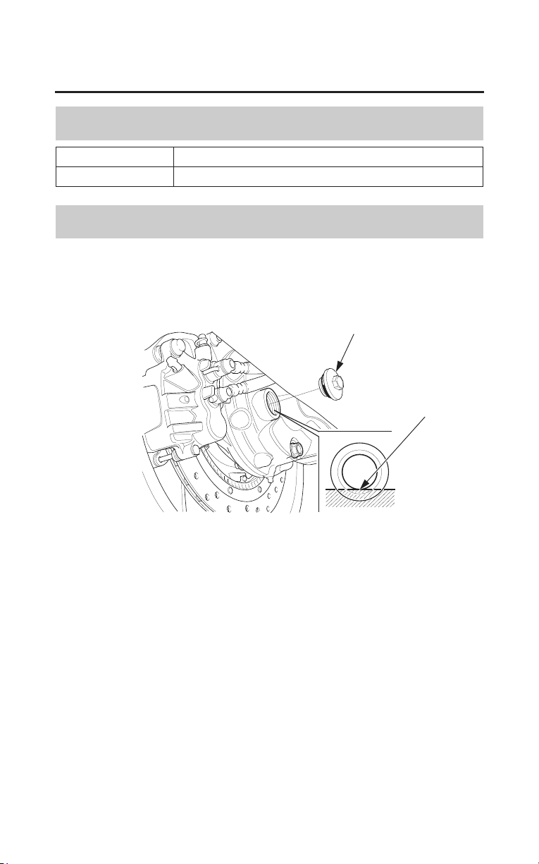
186
Servicing Your Honda
Final Drive Oil
Oil Recommendation
type hypoid gear oil
viscosity (weight) SAE 80
Checking & Adding Oil
Refer to Safety Precautions on page 154.
RIGHT REAR
oil fill cap
lower edge
1. Place the motorcycle on its center stand on a firm, level surface.
2. Remove the oil fill cap.
3. Check the oil level. It should be flush with the lower edge of the oil fill hole.
4. If the level is low, check for oil leaks. Add the recommended oil through the
oil fill hole until it reaches the lower edge of the opening.
5. Install the oil fill cap.
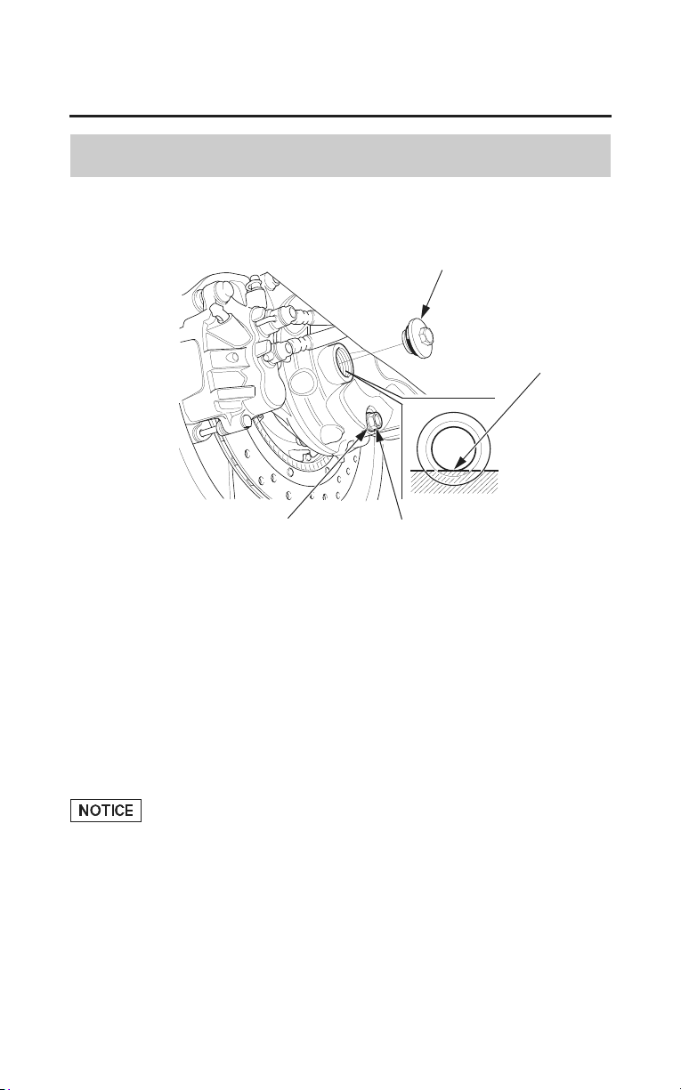
Servicing Your Honda
187
Final Drive Oil
Changing Oil
Refer to Safety Precautions on page 154.
oil fill cap
lower edge
sealing washer drain bolt
RIGHT REAR
Change the oil with the final drive at normal operating temperature to assure
complete and rapid draining.
1. Place the motorcycle on its center stand on a firm, level surface.
2. Place a drain pan under the drain bolt.
3. Remove the oil fill cap, drain bolt and sealing washer.
4. After the oil has completely drained, check that the sealing washer is in good
condition. Reinstall the drain bolt with i
ts sealing washer (or a new washer, if
necessary) and tighten it to the specified torque:
15 lbf·ft (20 N·m , 2.0 kgf·m)
5. Pour the drained oil into a suitable container and dispose of it in an approved
manner (page 223).
Improper disposal of drained fluids is harmful to the environment.
6. Fill the final drive with the recommended oil:
4.1 US oz (120 cm
3
)
Make sure the final drive oil level is at the lower edge of the oil fill inspection
hole.
7. Install the oil fill cap.
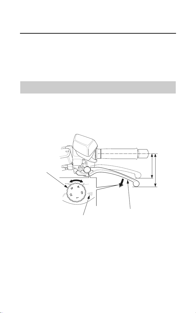
188
Servicing Your Honda
Clutch System
Your motorcycle has a hydraulically-actuated clutch. There are no adjustments
to perform, but the clutch system must be inspected periodically for fluid level
and leakage.
If the motorcycle creeps or stalls when shifted into gear, or if the clutch slips,
causing acceleration to lag behind engine speed, there is probably air in the
clutch system. See your dealer to have the air bled out of the system.
Clutch Lever Adjustment
Refer to Safety Precautions on page 154.
The distance between the tip of the clutch lever and the grip may be adjusted.
LEFT HANDLEBAR
adjuster dial
index mark
clutch lever
1. Turn the adjuster dial while pushing the clutch lever forward.
2. Align the index mark on the clutch lever with the numbers on the adjuster
dial.
3. Start the engine, pull the clutch lever in, and shift into gear. Make sure the
engine does not stall and the motorcycle does not creep. Gradually release the
clutch lever and open the throttle. Your motorcycle should move smoothly
and accelerate gradually.
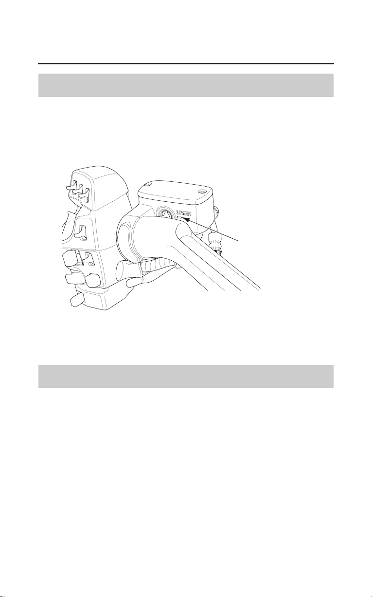
Servicing Your Honda
189
Clutch System
Fluid Level Inspection
Refer to Safety Precautions on page 154.
LEFT HANDLEBAR
LOWER level mark
Check that the fluid level is above the LOWER level mark. If the fluid level is
below the LOWER level mark, it indicates fluid leakage. See your dealer for
repair.
Other Inspections
• Make sure there are no fluid leaks.
• Check for deterioration or cracks in the hose and fittings.
• Check that the clutch lever assembly is positioned properly and the securing
bolts are tight.
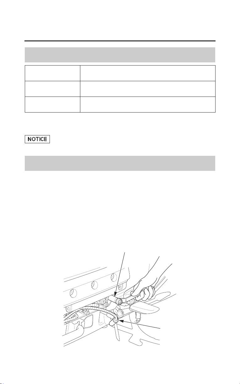
190
Servicing Your Honda
Spark Plugs
Spark Plug Recommendation
standard spark
plug
BKR6E-11 (NGK) or K20PR-U11 (DENSO)
for cold climate
(below 5°C, 41°F)
BKR5E-11 (NGK) or K16PR-U11 (DENSO)
for extended high
speed riding
BKR7E-11 (NGK) or K22PR-U11 (DENSO)
Use only the recommended type of spark plugs in the recommended heat range.
Using spark plugs with an improper heat range can cause engine damage.
Spark Plug Inspection & Replacement
Refer to Safety Precautions on page 154.
1. Remove the left and right cylinder head side cover (page 169).
2. Clean any dirt from around the spark plug bases.
3. Disconnect the spark plug caps. Take care to avoid damaging the spark plug
wire when disconn
ecting the caps.
4. Using a spark plug wrench provided in the tool kit (Canada model only),
remove the spark plugs.
spark plug wrench
spark plug cap
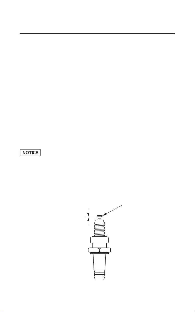
Servicing Your Honda
191
Spark Plugs
5. Inspect the electrodes and center porcelain for deposits, corrosion, or carbon
fouling. If the corrosion or deposits are heavy, replace the plug. Clean a
carbon or wet-fouled plug with a plug cleaner, if available, or a wire brush.
6. Check the spark plug gap using a wire-type feeler gauge. If adjustment is
necessary, bend the side electrode carefully.
The gap should be:
0.039 – 0.043 in (1.00 – 1.10 mm)
7. With the plug washers attached, install the spark plugs in by hand to prevent
cross-threading.
8. Tighten each spark plug:
• If the old plug is good:
1/8 turn after it seats.
• If installing a new plug, tighten it twice to prevent loosening:
a) First, tighten the plug:
NGK: 3/4 turn after it seats.
DENSO: 1/2 turn after it seats.
b) Then loosen the plug.
c) Next, tighten the plug again:
1/8 turn after it seats.
An improperly tightened spark plug can damage the engine. If a plug is too
loose, a piston may be damaged. If a plug is too tight, the threads may be
damaged.
9. Reinstall the spark plug caps. Take care to avoid pinching any cables or
wires.
10.Reinstall the left and right cylinder head side covers.
side electrode
spark plug gap

192
Servicing Your Honda
Suspension
Your front and rear suspension systems use springs and hydraulic damping
devices that suspend your weight and most of the weight of your motorcycle.
The spring pre-load for your rear suspension system adjusts the amount of force
required to begin compression of the spring.
The oil damper systems hydraulically control the natural compression and
rebound of the suspension springs so that traction and comfort are maintained as
the wheels ride over road surfaces.
Consider adjusting your rear suspension pre-load whenever you change your
normal load, when adding or removing a passenger, cargo, or accessories, or
when the road or riding conditions change.
The way you ride your motorcycle and the type of ride you want to experience
can also influence your suspension needs.
Lower spring pre-load provides a softer ride and is usually preferred for light
loads and smooth roads. Higher spring pre-load provides a firmer ride and is
recommended for heavy loads, rough road conditions, and faster, more
challenging riding.
Rear Suspension Adjustment
The rear suspension can be adjusted for rider (and passenger) weight and riding
conditions by changing the spring pre-load.
Do not attempt to disassemble, service, or dispose of the damper; see your
dealer. The instructions found in this owner’s manual are limited to adjustments
of the shock assembly only.
Rear Suspension Spring Pre-load Adjustment
Rear suspension spring pre-load can be easily increased or decreased using the
rear suspension spring pre-load adjustment switch on the right fairing panel.
Then you can confirm the pre-load position with the multi information display.
This rear suspension spring pre-load adjustment system functions only when the
ignition switch is ON or ACC, your motorcycle is stopped, and the transmission
is in neutral. (When the reverse indicator is ON, the system will not function.)
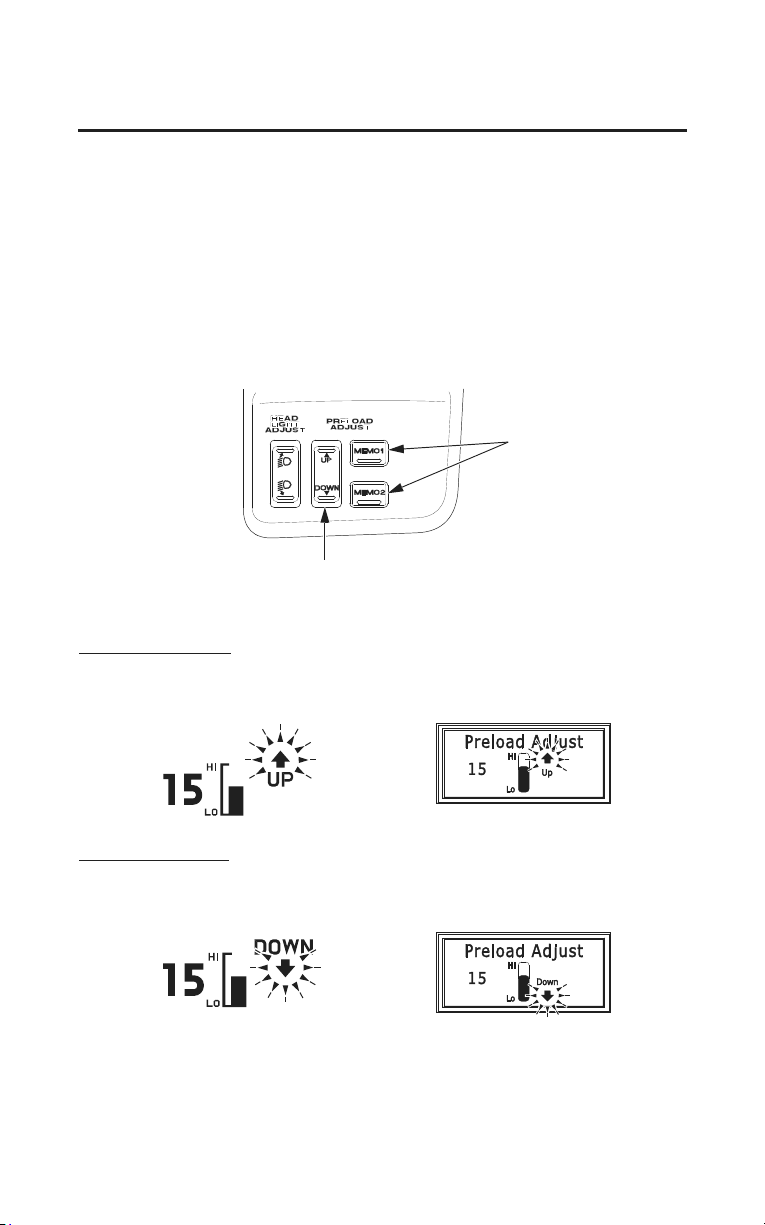
Servicing Your Honda
193
Suspension
The rear suspension spring pre-load adjustment system has 26 positions (from
0 to 25) for different road or riding conditions. (Standard position is 0.)
Adjustment
1. Place the motorcycle on its center stand on a firm, level surface. To prevent
discharging the battery, make sure the audio system and other electrical
accessories are off.
2. Turn the ignition switch to ON or ACC.
3. Push the DOWN or UP side of rear suspension spring pre-load adjustment
switch
until the desired pre-load is reached.
MEMO button
rear suspension spring pre-load
adjustment switch
To increase (HIGH)
(Models not equipped with
Navigation System)
(Models equipped with
Navigation System)
To decrease (LOW)
(Models not equipped with
Navigation System)
(Models equipped with
Navigation System)
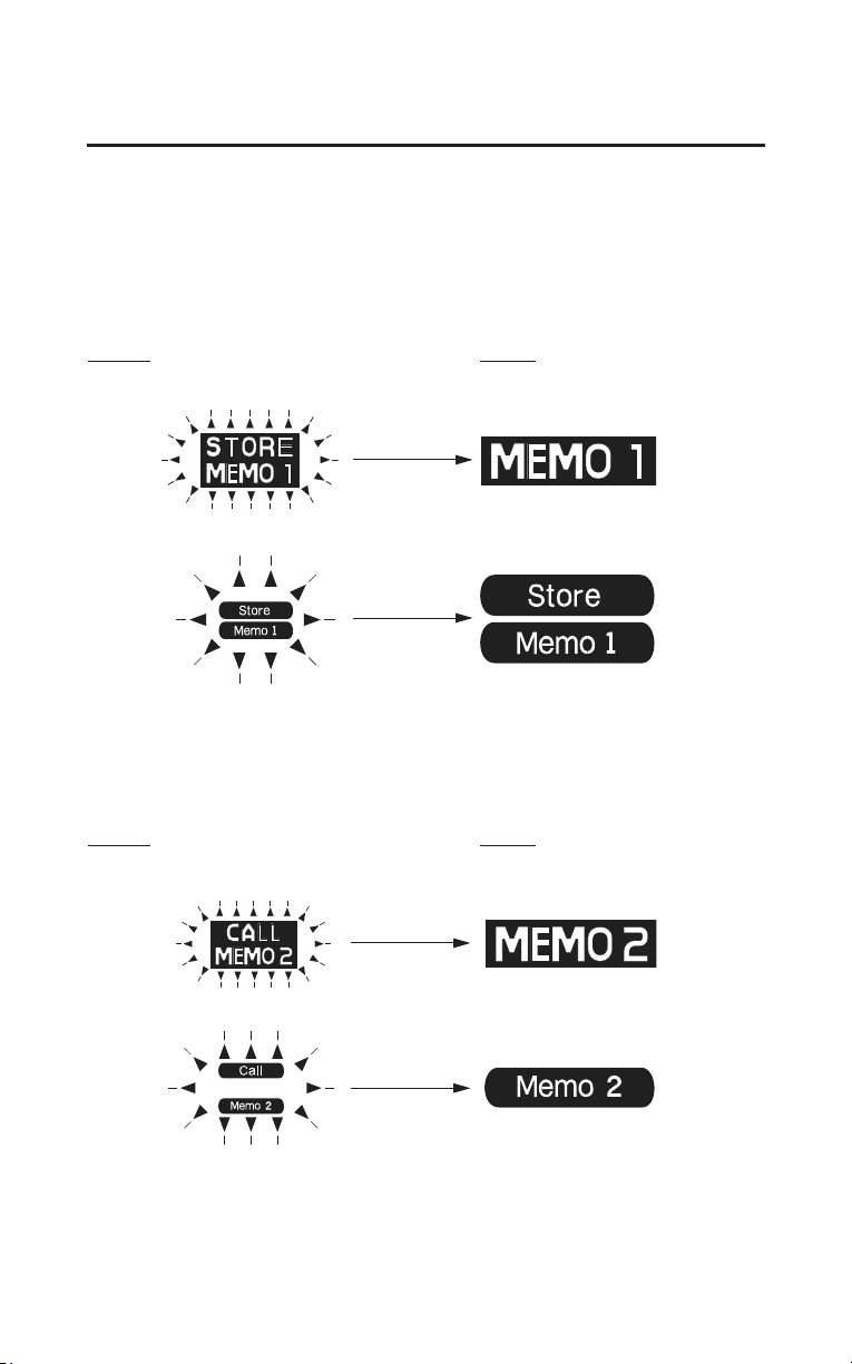
194
Servicing Your Honda
Suspension
Storing Pre-load Into the Memory
You may store two selected adjustments in ‘‘MEMO 1’’ or ‘‘MEMO 2’’.
1. Adjust the pre-load to the desired position.
2. Push and hold the MEMO 1 or MEMO 2 button until ‘‘STORE MEMO 1’’ or
‘‘STORE MEMO 2’’ blinks in the multi information display. When the
blinking stops, the current position is stored in memory.
Storing
Stored
(Models not equipped with Navigation System)
(Models equipped with Navigation System)
Selecting the Memorized Position
• Push the MEMO (1 or 2) button to select the memorized position. ‘‘CALL
MEMO 1’’ or ‘‘CALL MEMO 2’’ will blink. When the position is selected,
‘‘MEMO 1’’ or ‘‘MEMO 2’’ will turn on.
Calling
Called
(Models not equipped with Navigation System)
(Models equipped with Navigation System)
Pushing the rear suspension spring pre-load adjustment switch or the MEMO
(1 or 2) button while selecting a memorized position will cancel the calling
procedure.
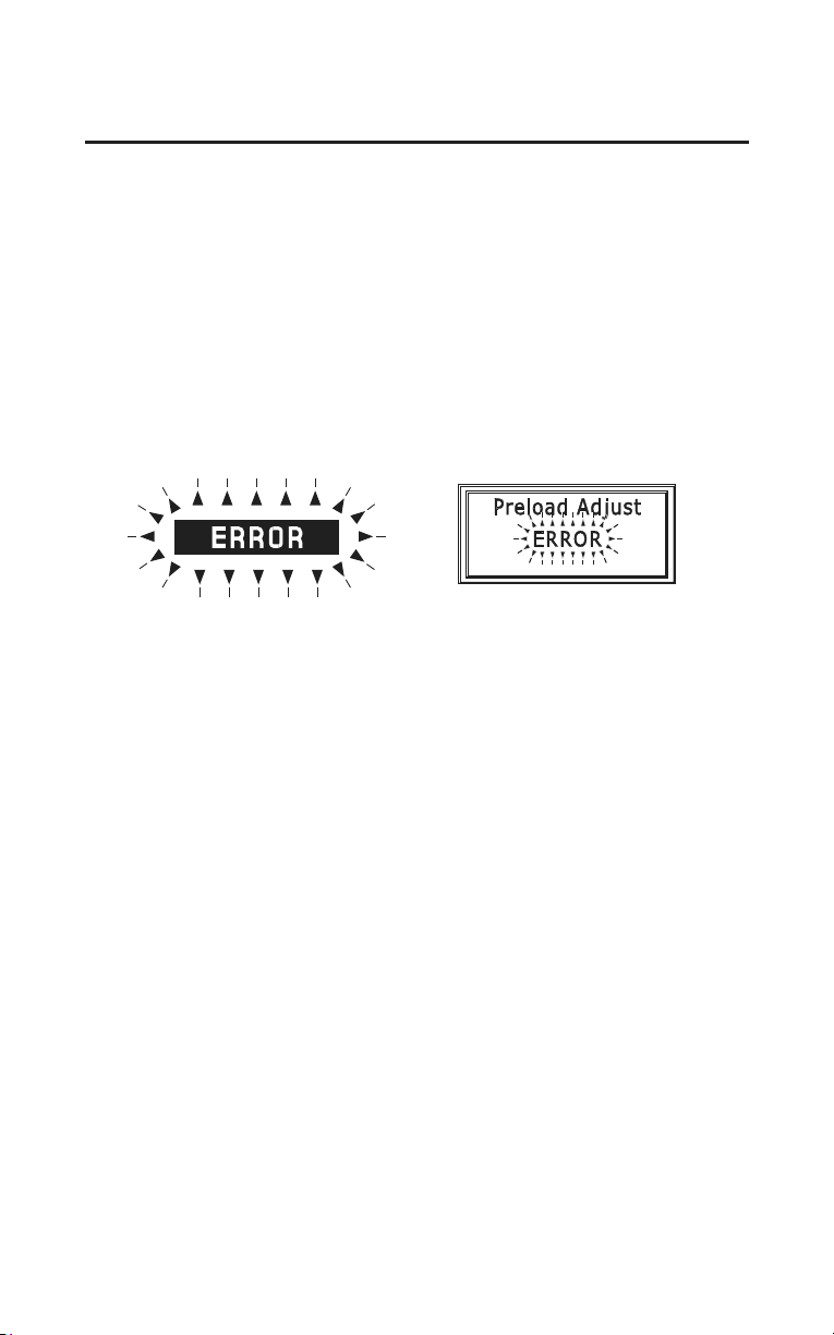
Servicing Your Honda
195
Suspension
Each MEMO button stores only one pre-load position. Storing a new position
erases the previous setting stored in that button’s memory. If you want to add a
new position while retaining the current one, use the other memory button.
All stored pre-load positions will be lost if your motorcycle’s battery goes low
(or dead) or is disconnected.
If ‘‘ERROR’’ blinks on the display, contact your dealer.
(Models not equipped with
Navigation System)
(Models equipped with
Navigation System)
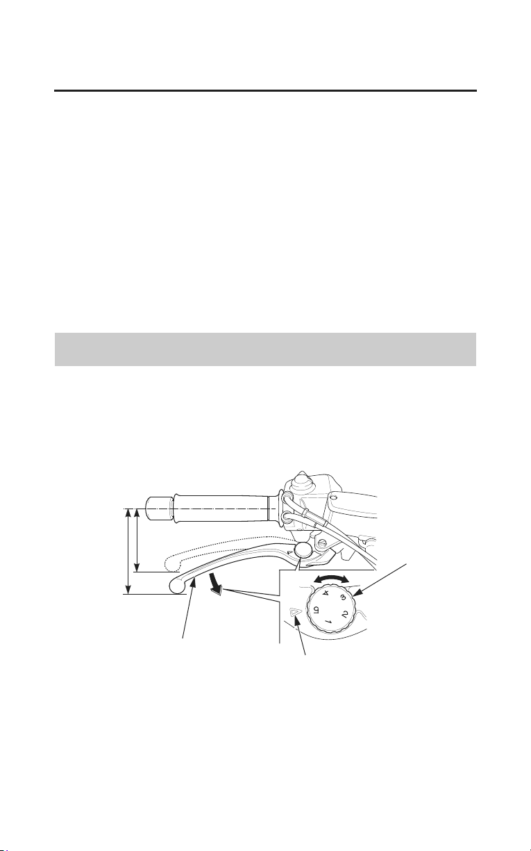
196
Servicing Your Honda
Brakes
The hydraulic braking systems on your motorcycle dissipate the heat generated
by the friction of the brake pads on the brake discs as the wheels are slowed.
As the brake pads wear, the brake fluid level will drop. A leak in the system will
also cause the level to drop.
Frequently inspect the system to ensure there are no fluid leaks. Periodically
inspect the brake fluid level and the brake pads for wear.
If the brake lever or brake pedal freeplay does not feel within the normal range
while riding, check the brake pads for wear (page 199). Worn pads should be
replaced. If the pads are not worn beyond the recommended limit, there is
probably air in the brake system. See your dealer to have the air bled from the
system.
Front Brake Lever Adjustment
Refer to Safety Precautions on page 154.
The distance between the tip of the brake lever and the grip may be adjusted.
RIGHT HANDLEBAR
brake lever
index mark
adjuster dial
1. Turn the adjuster dial while pushing the brake lever forward.
2. Align the index mark on the brake lever with the numbers on the adjuster
dial.
3. Apply the brake, release it, then spin the wheel and check that it rotates
freely. Repeat this procedure several times.
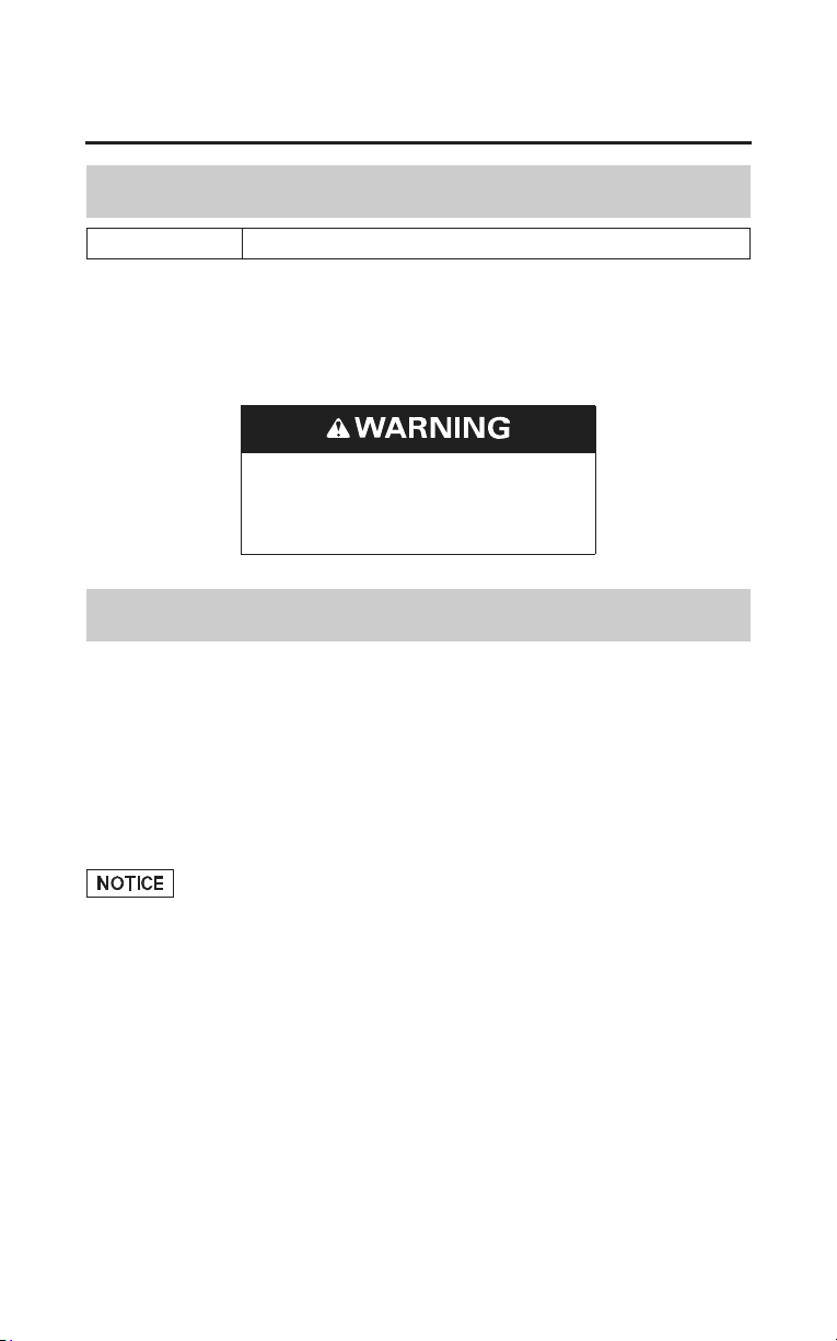
Servicing Your Honda
197
Brakes
Brake Fluid Recommendation
brake fluid Honda DOT 4 Brake Fluid
The recommended brake fluid is Honda DOT 4 Brake Fluid, or any brake fluid
of equal quality and performance. Use fresh brake fluid from a sealed container.
Be sure to read the label before opening the sealed container. An opened
container may be contaminated or may have absorbed moisture from the air.
Clean filler cap before removing.
Use only DOT4 fluid from a
sealed container.
Fluid Level Inspection
Refer to Safety Precautions on page 154.
If your inspection indicates a low fluid level, have your dealer add the
recommended brake fluid.
Do not add or replace brake fluid, except in an emergency. If you do add fluid,
have your dealer check the system as soon as possible.
Brake fluid can damage plastic and painted surfaces. Handle with care.
Wipe up spills immediately. Avoid brake fluid contact with skin or eyes. If it
comes in contact with your eyes, wash them out with clean water and
immediately call a doctor. If it comes in contact with your skin, wash with clean
water and, if necessary, call a doctor.
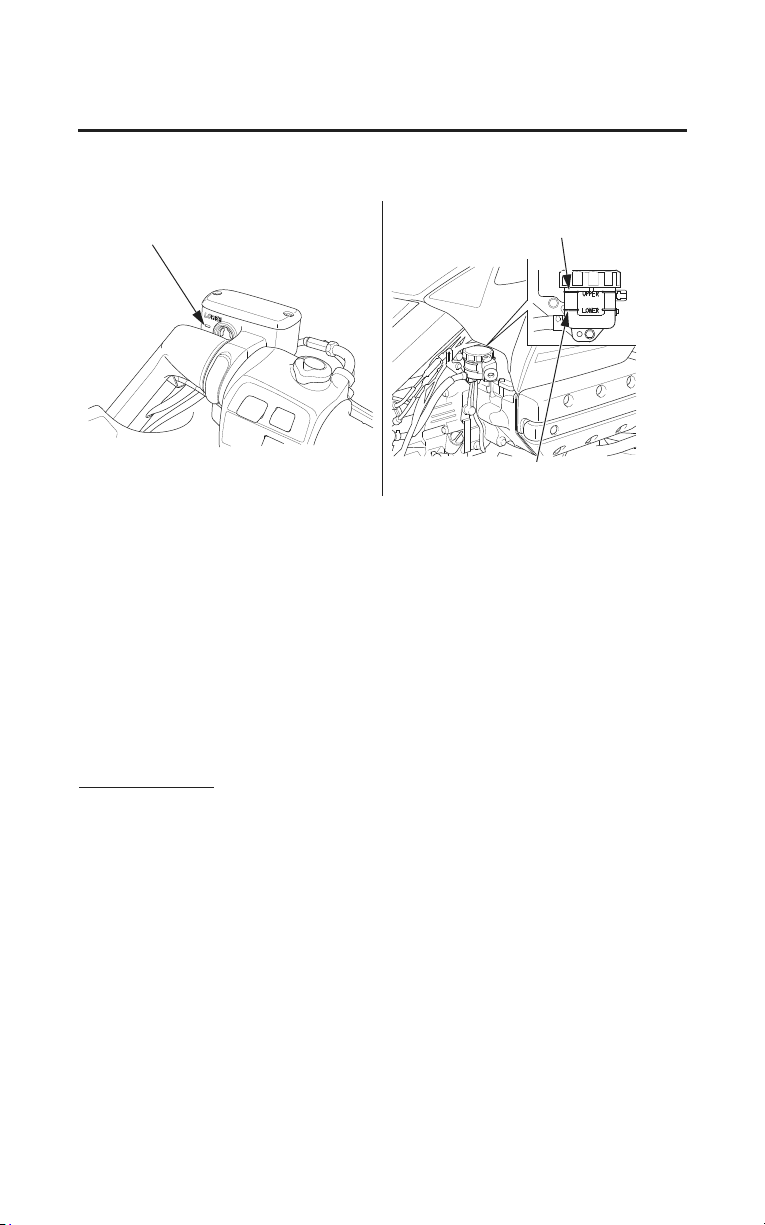
RIGHT HANDLEBAR
(Front Brake)
RIGHT SIDE
(Rear Brake)
LOWER level mark
UPPER level mark
LOWER level mark
198
Servicing Your Honda
Brakes
1. Place your motorcycle in an upright position on a firm, level surface.
2. Check the fluid level.
Front: It should be above the LOWER level mark.
Rear: It should be between the UPPER and LOWER level marks.
If the level is at or below the LOWER
level mark, check the brake pads for
wear.
Worn pads should be replaced. If the pads are not worn beyond the
recommended limit, have your brake system inspected for leaks.
Other Inspections
• Make sure there are no fluid leaks.
• Check for deterioration or cracks in the hoses and fittings.
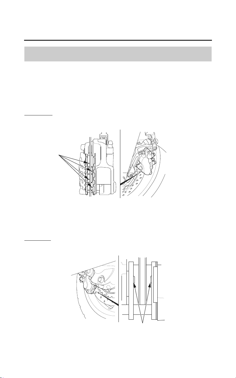
Servicing Your Honda
199
Brakes
Brake Pad Wear
Refer to Safety Precautions on page 154.
Brake pad wear depends upon the severity of usage, the type of riding, and road
conditions. Generally, the pads will wear faster on wet and dirty roads. Inspect
the pads at each regular maintenance interval (page 159).
Front Brake
LEFT FRONT (right side similar)
grooves
Always inspect both pads in both the right and left front brake calipers.
Check the grooves in each pad. If either pad is worn to the bottom of the
grooves, replace both pads as a set. See your dealer for this service.
Rear Brake
RIGHT REAR
cutouts
Check the cutouts in each pad. If either pad is worn to the cutout, replace both
pads as a set. See your dealer for this service.
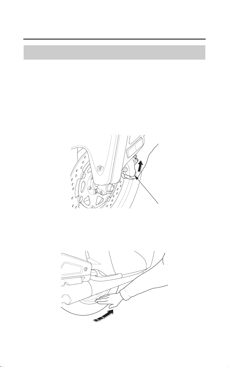
200
Servicing Your Honda
Brakes
Brake System Inspection
Refer to Safety Precautions on page 154.
1. Place the motorcycle on its center stand, stop the engine, and place the
transmission in neutral.
2. Move the left caliper assembly upward while slowly rotating the rear wheel.
The brake system is normal if the rear wheel stops. If the rear wheel does not
stop, see your dealer.
LEFT FRONT
brake caliper
LEFT REAR
Servicing Your Honda
201
Tires
To safely operate your motorcycle, your tires must be the proper type and size,
in good condition with adequate tread, and correctly inflated for the load you are
carrying.
Using tires that are excessively
worn or improperly inflated can
cause a crash in which you can
be seriously hurt or killed.
Follow all instructions in this
owner’s manual regarding tire
inflation and maintenance.
The following pages give detailed information on how and when to check your
air pressure, how to inspect your tires for wear and damage, and our
recommendations for tire repair and replacement.

202
Servicing Your Honda
Tires
Air Pressure
Refer to Safety Precautions on page 154.
Properly inflated tires provide the best combination of handling, tread life, and
riding comfort. Generally, underinflated tires wear unevenly, adversely affect
handling, and are more likely to fail from being overheated. Overinflated tires
make your motorcycle ride harshly, are more prone to damage from road
hazards, and wear unevenly.
Even though your motorcycle is equipped with tire pressure monitoring system
(TPMS), we
recommend that you visually check your tires before every ride and
use an air pressure gauge to measure the air pressure at least once a month or
any time you think the tires might be low. Even tires that are in good condition
may lose one to two psi per month if not checked and adjusted regularly.
See page 83 for more information.
Tubeless tires have some degree of self-sealing ability if they are punctured.
However, because leakage is often very slow, you should look closely for
punc
tures
whenever a tire is not fully inflated.
Always check air pressure when your tires are ‘‘cold’’, after the motorcycle has
been parked for at least three hours. If you check air pressure when your tires
are ‘‘warm’’ — even if your motorcycle has only been ridden for a few miles —
the readings will be higher. If you let air out of warm tires to match the
recommended cold pressures, the tires will be underinflated.
The recommended ‘‘cold’’ tire pressures are:
front
36 psi (250 kPa , 2.50 kgf/cm
2
)
rear
41 psi (280 kPa , 2.80 kgf/cm
2
)
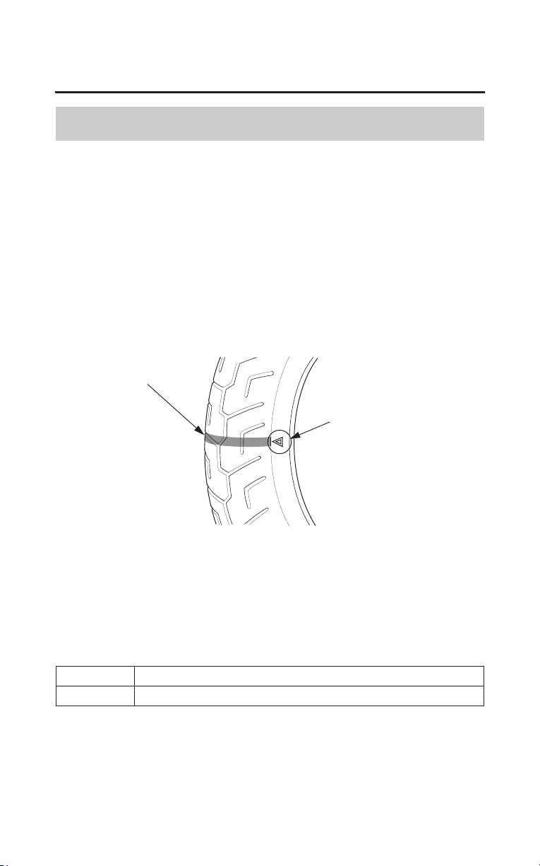
Servicing Your Honda
203
Tires
Inspection
Refer to Safety Precautions on page 154.
Whenever you check the tire pressures, you should also look for:
• Bumps or bulges in the side of the tire or the tread. Replace any tire that has a
bump or bulge.
• Cuts, slits, or cracks in the tires.
Replace the tire if you can see fabric or cord.
• Nails or other foreign objects embedded in the side of the tire or tread.
• Excessive tread wear.
wear indicator
wear indicator location
mark
Also, if you hit a pothole or hard object while riding, pull to the side of the road
as soon as you safely can and carefully inspect the tires for damage.
For the best performance, you should replace a tire before the tread depth at the
center reaches the following limits:
front 0.06 in (1.5 mm)
rear 0.08 in (2.0 mm)
If the wear indicators are visible, replace the tire immediately as it is no longer
safe.

204
Servicing Your Honda
Tires
Tire Service Life
The service life of your tires is dependent on many factors, including, but not
limited to, riding habits, road conditions, vehicle loading, tire pressure,
maintenance history, speed, and environmental conditions (even when the tires
are not in use).
In addition to your regular inspections and tire
pressure maintenance, it is
recommended that you have annual inspections performed once the tires reach 5
years old. It is also recommended that all tires be removed from service after 10
years from the date of manufacture, regardless of their condition or state of
wear.
The last four digits of the TIN (tire identification number) (1) are found on the
sidewall of the tire, and
indicate the date of manufacture.
Tire Identification Number (TIN)
The tire identification number (TIN) is a group of numbers and letters that look
like the following example.
The TIN is located on the sidewall of the tire.
DOT ××××
×××× 22 07
(2) (3) (4)
DOT – This indicates that the tire meets all requirements of the U.S.
Department of Transportation.
(2) ×××× – Factory code
(3) ×××× – Tire type code
(4) 22
07 – Date of manufacture
Year
Week
TIRE LABELING EXAMPLE
(1)
(1) tire identification number (TIN)

Servicing Your Honda
205
Tires
Tire Repair
Refer to Safety Precautions on page 154.
We strongly recommend that you replace, not repair, any tire that is punctured
or damaged. As discussed below, a tire that is repaired, either temporarily or
permanently, will have lower speed and performance limits than a new or
undamaged tire.
A temporary repair can sometimes be made in an emergency situation.
However, since a temporary repair may not hold, you must ride very slowly,
preferably without any cargo or passenger
, and have the tire replaced or
permanently repaired as soon as possible.
(For more information on temporary repairs, see If You Have a Flat Tire, page
230.)
Using a puncture-repairing agent can damage the TPMS sensors, causing the
TPMS indicator to turn on. Have you motorcycle checked by your dealer as
soon as possible.
Use caution to not damage the TPMS sensor if an internal plug patch must be
used to repair the tire. If you have a tire professionally repaired at a non-Honda
facility, we recommend that you have the work checked by your dealer. TPMS
wheels require special handling when changing the tire. Failure to follow the
proper tire replacement procedure can result in damage to the TPMS sensor.
206
Servicing Your Honda
Tires
A permanent repair, such as an internal plug patch, can be made if a tire has only
a small puncture in the tread area. With such a repair, you should not exceed 50
mph (80 km/h) for the first 24 hours, or 80 mph (130 km/h) at any time
thereafter. In addition, you may not be able to safely carry as much weight. If
you choose to have a tire repaired, be sure the repair work is performed by a
professional and that the wheel is balanced before you ride.
If you have a tire professionally repaired at a non-Honda facility, we
recom
mend that you have the work checked by your dealer.
Tire Replacement
Refer to Safety Precautions on page 154.
The tires that came on your motorcycle were designed to match the performance
capabilities of your motorcycle and provide the best combination of handling,
braking, durability, and comfort.
When replacing, use the original equipment tires or equivalent tires of the same
size, construction, speed rating, and load range as the originals.
Installing improper tires on your
motorcycle can affect handling
and stability. This can cause a
crash in which you can be
seriously hurt or killed.
Always use the size and type of
tires recommended in this
ow
ner’s manual.

Servicing Your Honda
207
Tires
The recommended tires for your motorcycle are:
front BRIDGESTONE G709 RADIAL 130/70R18M/C 63H
rear BRIDGESTONE G704 RADIAL 180/60R16M/C 74H
type radial, tubeless
Whenever you replace a tire, remember:
• Have the wheel balanced after the tire is installed.
• Have the tire replaced by your dealer.
Important Safety Reminders
• Do not install a tube inside a tubeless tire on this motorcycle. Excessive heat
build-up can cause the tube to burst.
• Use only tubeless tires on this motorcycle. The rims are designed for tubeless
tires, and during hard acceleration or braking, a tube-type tire could slip on
the rim and cause the tire to rapidly deflate.
• Do not install car tires on this motorcycle. During installation the tire may
separate from the rim with enough force to cause serious injury or death.
• When replacing tires, use only the recommended tires as shown above and on
the tire information label. Use of other tires on the model equipped with ABS
may impair proper ABS function. The ABS computer works by comparing
wheel speed.
Non-recommended tires can affect wheel speed and may confuse the ABS
computer.
•If you ever replace a wheel, make sure that the wheel’s specifications match
those of the original wheels.
Be sure you use only TPMS-specific wheels. Not using TPMS-specific
wheels can cause an air leak, a tire pressure monitoring system failure, or
both.
Replacement wheels are available at your dealer.
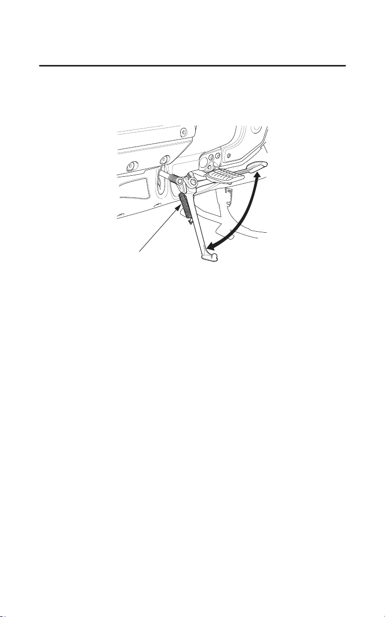
208
Servicing Your Honda
Side Stand
Refer to Safety Precautions on page 154.
LEFT SIDE
side stand spring
• Check that the side stand assembly is working properly. If the side stand is
stiff or squeaky, clean the pivot area and lubricate the pivot bolt with clean
grease.
• Check the side stand spring for damage or loss of tension.
• Check the side stand ignition cut-off system:
1. Sit on the motorcycle and put the transmission in neutral.
2. Raise the side stand.
3. Start the engine.
4. Pull the clutch lever in.
5. Shift the transmission into gear.
6. Lower the side stand all the way.
The engine should stop as you lower the side sta
nd. If the engine doesn’t
stop,
see your dealer for service.

Servicing Your Honda
209
Battery
Your motorcycle has a maintenance-free type battery. You do not have to check
the battery electrolyte level or add distilled water as you would with a
conventional-type battery.
Your battery is a maintenance-free type and can be permanently damaged if the
cap strip is removed.
Electrical accessories use current from the battery, even when the ignition is
OFF. Limited operation also allows the battery to discharge. If you have
electrical accessories on your motorcycle or do not ride frequently, we
recommend that you charge the battery frequently (see Battery Charging, page
212).
If you do not expect to ride your motorcycle for at least two weeks, we
recommend you
remove the battery, or at least disconnect the battery cables
(negative cable first).
If you plan to store your motorcycle, see Battery Storage, page 210.
If your battery seems weak and/or is leaking electrolyte (causing slow starting
or other electrical problems), see your dealer.
WARNING: Battery posts, terminals and related accessories contain lead and
lead compounds. Wash your hands after handling.
210
Servicing Your Honda
Battery
Battery Storage
Refer to Safety Precautions on page 154.
If you plan to store your motorcycle, we recommend you remove the battery and
store it where it can be charged at least every 30 days to maintain its service life.
If you do not remove the battery, we recommend disconnecting the battery
cables (negative cable first).
You will get the best storage results from removing the battery and slow
charging it every 30 days (see Battery Charging, page 212).
Before you remove the battery, be sure to read all the information that follows,
as well as the information on the battery label.
The battery gives off explosive
hydrogen gas during normal
operation.
A spark or flame can cause the
battery to explode with enough
force to kill or seriously hurt you.
Wear protective clothing and a
face shield, or have a skilled
mechanic do the battery
maintenance.
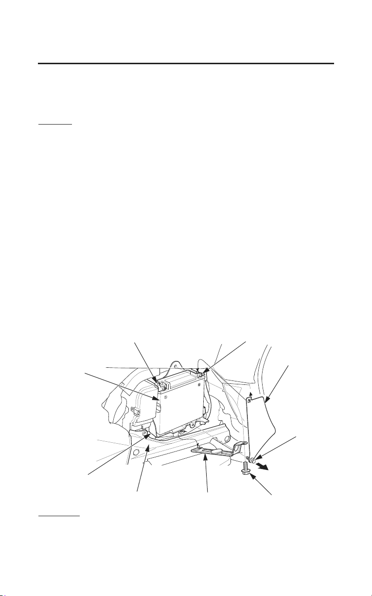
Servicing Your Honda
211
Battery
The battery is located in the battery box behind the left side cover.
After turning the ignition switch OFF, wait more than 10 seconds and then
remove the negative cable of the battery. The Navigation system may not
function correctly.
Removal
1. Make sure the ignition switch is OFF.
2. Remove the left side cover (page 167).
3. Pull the clip and remove the battery plate.
4. Disconnect the negative (–) terminal lead from the battery first.
5. Remove the bolt and open the battery holder.
6. Disconnect the positive (㻗) terminal lead.
7. Pull the battery out of the battery box.
Be careful to avoid damaging the cover under the battery box when you
remove the battery.
8. Charge the battery (see following section), unless you have been riding
regularly.
9. Store your battery in an easy-to-reach location off the floor, in an area
protected from freezing temperatures and direct sunlight.
10.Clean the battery box after removing the battery for storage. Dry the battery
box and, if paint is missing, re-paint the area.
11. Slow charge the battery (see following section) once every 30 days.
LEFT SIDE
positive (+) terminal lead
bolt
cover
negative (–) terminal lead
battery
battery box
battery holder
clip
battery plate
Installation
1. Reinstall in the reverse order of removal. Be sure to connect the positive (+)
terminal first, then the negative (–) terminal.
2. Check all bolts and other fasteners are secure.
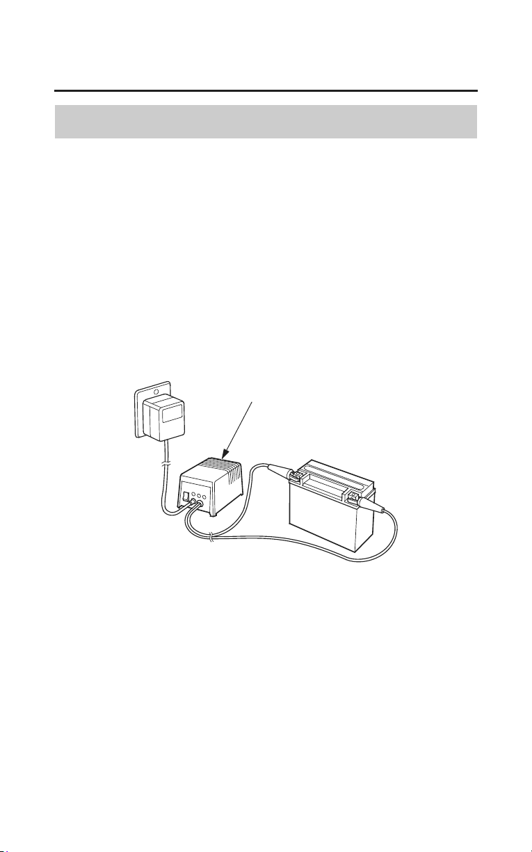
212
Servicing Your Honda
Battery
Battery Charging
Refer to Safety Precautions on page 154.
Be sure to read the information that came with your battery charger and follow
the instructions on the battery. Improper charging may damage the battery.
We recommend using a charger designed specifically for your Honda, which
can be purchased from your dealer. These units can be left connected for long
periods without risking damage to the battery. However, do not intentionally
leave the charger connected longer than the time period recommended in the
charger’s instructions.
Avoid using an automotive-type battery charger. An automotive charger can
overheat a motorcycle battery and cause permanent damage.
charger

Servicing Your Honda
213
Appearance Care
Frequent cleaning and polishing will keep your Honda looking newer longer.
Frequent cleaning also identifies you as an owner who values your motorcycle.
A clean motorcycle is also easier to inspect and service.
General Recommendations
Refer to Safety Precautions on page 154.
• To clean your motorcycle, you may use:
– water
– a mild, neutral detergent and water
– a mild spray and wipe cleaner/polisher
– a mild spray and rinse cleaner/degreaser and water
• Avoid products that contain harsh detergents or
chemical solvents that could
damage the metal, paint, and plastic on your motorcycle.
• If your motorcycle is still warm from recent operation, give the engine and
exhaust system time to cool off.
• Park in a shady area. Washing your motorcycle in bright sunlight may cause
the finish to fade because water droplets intensify the sun’s brightness.
Spotting is also more likely because surface water can dry before you have
time to wipe it off.
• Clean your motorcycle regularly to protect surface finishes.
• We recommend the use of a garden hose to wash your motorcycle. High
pressure washers (like those at coin-operated car washes) can damage certain
parts of your motorcycle.
The audio system is designed to be weatherproof unless it is sprayed directly
with hose.
High pressure water (or air) can damage certain parts of your motorcycle.
• After cleaning, inspect for damage, wear, and leaks (fuel, oil, coolant, brake,
and clutch fluid).

214
Servicing Your Honda
Appearance Care
Washing Your Motorcycle with a Mild Detergent
Refer to Safety Precautions on page 154.
1. Rinse your motorcycle thoroughly with cool water to remove loose dirt.
2. Fill a bucket with cool water. Mix in a mild, neutral detergent, such as dish
washing liquid or a product made especially for washing motorcycles or
automobiles.
3. Wash your motorcycle with a sponge or a soft towel. As you wash, check for
heavy grime. If necessary, use a mild cleaner/degreaser to remove the grime.
If the inside of the headlight lens appears clouded immediately after washing,
it should clear after a few minutes of riding.
4. After washing, rinse your motorcycle thoroughly with plenty of clean water
to remove any residue. Detergent residue can corrode alloy parts.
5. Dry your motorcycle with a chamois or a soft towel. Leaving water on the
surface to air dry can cause dulling and water spots. As you dry, inspect for
chips and scratches.
6. Start the engine and let it idle for several minutes. The engine heat will help
dry moist areas.
7. As a precaution, ride your motorcycle at a slow speed and apply the brakes
several times. This will help dry the brakes and restore normal braking
performance.

Servicing Your Honda
215
Appearance Care
Cleaning the Windscreen
Refer to Safety Precautions on page 154.
Using plenty of water, clean the windscreen with a soft cloth or sponge. (Avoid
using detergents or any kind of chemical cleaner on the windscreen.) Dry with a
soft, clean cloth.
To avoid possible scratching or other damage, use only water and a soft cloth or
sponge to clean the windscreen.
For a dirtier windscreen, use a diluted neutral detergent with a sponge and
plenty of water. Make sure to wash off all the detergent. (Detergent residue may
cause windscreen cracks.)
Replace the windscreen if scratches cannot be removed and they obstruct clear
vision.
Take care to keep battery electrolyte, brake fluid, or other chemical solvents off
the
windscreen and screen garnish. They will damage the plastic.
Cleaning the Display and Light Lens
Clean the display and light lens with a soft, damp cloth. You may use a mild
cleaner intended for eyeglasses or computer displays.
Harsher chemicals may damage the display and light lens.
To avoid possible scratching or other damage, use only water and a soft cloth
or sponge to clean the display and light lens.
Take care to keep battery electrolyte, brake fluid, or other chemical solvents off
the display and light lens. They will damage the display and light lens.
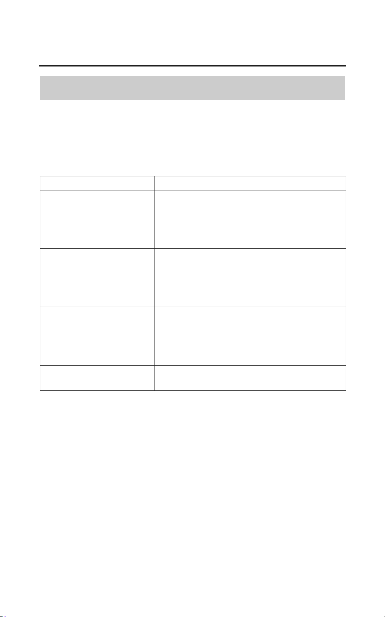
216
Servicing Your Honda
Appearance Care
Spray Cleaning Your Motorcycle
Refer to Safety Precautions on page 154.
Avoid using spray cleaner products on the tires or suspension components.
Suggestions for using spray cleaner(s) follow:
Motorcycle Condition Recommended Cleaning
General cleaning.
Polishing paint, chrome,
glass, and clear plastic.
Dust. Fingerprint
smudges.
Apply a spray cleaner/polish and wipe
with a non-abrasive cloth.
Light road grime. Spray any difficult-to-reach or very dirty
areas with a spray cleaner/degreaser.
Rinse and dry.
Apply a spray cleaner/polish and wipe
with a non-abrasive cloth.
Heavy grime. Oil leaks.
Brake dust.
Use a spray cleaner/degreaser.
If necessary, rub with a sponge.
Rinse and dry.
Apply a spray cleaner/polish and wipe
with a non-abrasive cloth.
Dull, corroded
chrome
or aluminum.
Apply a high quality chrome/aluminum
polish and wipe with a non-abrasive cloth.

Servicing Your Honda
217
Appearance Care
Aluminum Wheel Maintenance
Refer to Safety Precautions on page 154.
Aluminum may corrode from contact with dirt, mud, or road salt. Clean the
wheels after riding through any of these substances. Use a wet sponge and mild
detergent, or a commercially-available spray cleaner/degreaser designed for use
on aluminum. Avoid stiff brushes, steel wool, or cleaners containing abrasives
or harsh chemical compounds.
After washing, rinse with plenty of water and dry with a clean cloth. Then apply
a mild, co
mmercially-available spray cleaner/polish or wax.
After you finish cleaning the wheels, it’s important to check for and remove any
cleaner or polish residue found on the brake discs or pads. Use Honda Contact/
Brake Cleaner or an equivalent brake degreasing agent.
Clean the Matte Painted Surface
Refer to Safety Precautions on page 154.
Use a soft cloth or sponge, plenty of water, and a mild detergent to clean the
matte paint. Dry with a soft, clean cloth.
Do not use polishing compounds or wax containing polishing compounds.
These can damage or discolor the matte painted surface.
To keep your Honda looking new, clean and polish it frequently.

218
Servicing Your Honda
Appearance Care
Exhaust Pipe And Muffler Maintenance
Refer to Safety Precautions on page 154.
The exhaust pipe and muffler are stainless steel but may become stained by mud
or dust.
To remove mud or dust, use a wet sponge and a liquid kitchen abrasive, then
rinse well with
clean water. Dry with chamois or a soft towel.
If necessary, remove heat stains by using a commercially available fine texture
compound. Then rinse by the same manner as removing mud or dust.
When the exhaust pipe and muffler are painted, do not use a commercially
available abrasive kitchen cleaning compound. Use a neutral detergent to clean
the painted surface on the exhaust pipe and muffler. If you are not sure if your
exhaust pipe and muffler are painted, contact your dealer.
Finishing Touches
Refer to Safety Precautions on page 154.
After washing your motorcycle, consider using a commercially available spray
cleaner/polish or quality liquid or paste wax to finish the job. Use only a non-
abrasive polish or wax made specifically for motorcycles or automobiles. Apply
the polish or wax according to the instructions on the container.
If a surface on your motorcycle is chipped or scratched, your dealer has touch-
up paint to match your motorcycle’s color. Be sure to use your motorcycle’s
color code (page 253) when you buy touch-up paint.
If the frame has a chip that exposes the metal, first apply primer (to prevent
corrosion) and then apply the touch-up paint. Several thin layers of touch-up
paint are better than one thick coat.

Tips
219
Tips
Here’s a few helpful tips on how to store and transport your Honda, and how to
be an environmentally responsible motorcycle owner.
Storing Your Honda........................................................................................ 220
Transporting Your Motorcycle ....................................................................... 222
You & the Environment ................................................................................. 223

220
Tips
Storing Your Honda
If you won’t be riding for an extended period, such as during the winter,
thoroughly inspect your motorcycle and correct any problem before storing it.
That way, needed repairs won’t be forgotten and it will be easier to get your
motorcycle running again.
For more information about storage, refer to the Hon
da Winter Storage Guide,
available from your dealer (USA only).
We suggest you perform the following procedures to keep your motorcycle in
top condition. These storage procedures will reduce the deterioration that can
occur during storage.
Preparation for Storage
Refer to Safety Precautions on page 154.
This procedure requires a means for draining and disposing of drained fuel
(page 223).
1. Change the engine oil and filter (page 179).
2. Make sure the cooling system is filled with a 50/50% antifreeze solution
(page 182).
3. Fill the fuel tank. Make sure the fuel fill cap is properly installed.
4. To prevent rusting in the cylinders, perform the following:
• Remove the spark plug caps from the spark plugs. Using tape or string,
secure the caps to any convenient plastic body part so that they are
positioned away from the spark plugs.
• Remove the spark plugs from the engine and store them in a safe place. Do
not connect the spark plugs to the spark plug caps.
• Pour a tablespoon (15 – 20 cc) of clean engine oil into each cylinder and
cover the spark plug holes with a piece of cloth.
• With the engine stop switch in the RUN position, press the start button
several times to crank the engine and distribute the oil.
• Reinstall the spark plugs and spark plug caps.

Tips
221
Storing Your Honda
5. Remove the battery and charge it fully. Store it in an area protected from
freezing temperatures and direct sunlight. Slow charge the battery (page 212)
once a month.
6. Wash and dry your motorcycle. Wax all painted surfaces. Apply rust-
inhibiting oil to the chrome pieces.
7. Inflate the tires to their recommended pressures (page 202).
8. Store your motorcycle in an unheated area, free of dampness, away from
sunlight, with a minimum of daily temperature variation.
9. Cover your motorcycle with a porous material. Avoid using plastic or similar
non-breathing, coated materials that restrict air flow and allow heat and
moisture to accumulate.
Removal from Storage
Refer to Safety Precautions on page 154.
1. Uncover and clean your motorcycle.
2. If your motorcycle has been stored for more than four months — change the
engine oil (page 179).
3. If your motorcycle has been stored for more than two months — ask your
dealer to drain and replace the fuel.
4. Charge the battery (page 212) as required. Install the battery.
5. Perform a pre-ride inspection (page 47), then test-ride your motorcycle at low
speeds.

222
Tips
Transporting Your Motorcycle
If your motorcycle needs to be transported, it should be carried on a motorcycle
trailer, or a truck or trailer with a flatbed area. Do not tow your motorcycle, as
towing can seriously damage the transmission.
When contacting a towing or transporting service, be sure to ask if they have a
flatbed area, a loading ramp or power ramp to safely lift the motorcycle, and
motorcycle tie-down straps.

Tips
223
You & the Environment
Owning and riding a motorcycle can be enjoyable, but you must do your part to
protect nature.
Following are tips on how you can be an environmentally responsible
motorcycle owner.
• Choose Sensible Cleaners. Use a biodegradable detergent when you wash
your motorcycle. Avoid aerosol spray cleaners that contain
chlorofluorocarbons (CFCs) which damage the atmosphere’s protective
ozone layer. Don’t throw cleaning solvents away; see the following
guidelines for proper disposal.
• Recycle Wastes. It’s illegal and thoughtless to put used engine oil in the
trash, down a drain, or on the ground. Used oil, gasoline, coolant, and
cleaning solvents contain poisons that can hurt refuse workers and
contaminate our drinking water, lakes, rivers, and oceans. Before changing
your oil, make sure you have the proper containers. Put oil and other toxic
wastes in separate sealed containers and take them to a recycling center. Call
your local or state office of public works or environmental services to find a
recycling center in your area, and to get instructions on how to dispose of
non-recyclable wastes.

Taking Care of the Unexpected
225
Taking Care of the Unexpected
This section discusses the more common problems that can occur with your
motorcycle while you’re riding. It tells you how to evaluate each problem and
what actions you can take to try to resume riding. If the problem cannot be
safely solved, this section also gives instructions on the proper way to have your
motorcycle transported.
For information about transporting your motorcycle, see page 222.
General Guidelines.......................................
.................................................. 226
If Your Engine Quits or Won’t Start............................................................... 227
If You Have a Flat Tire................................................................................... 230
If Your Engine Overheats............................................................................... 241
If the Low Oil Pressure Indicator Lights........................................................ 243
If a Fuse Blows............................................................................................... 244
If You Crash ................................................................................................... 247
If You Lose Your Key .................................................................................... 248
If Your Battery Is Low (or Dead)................................................................... 249

226
Taking Care of the Unexpected
Taking Care of the Unexpected
General Guidelines
Keeping your motorcycle well-maintained is the best way to reduce the
possibility of having a problem on the road.
Remember to take along your owner’s manual, the tool kit that came with your
motorcycle, and any other items (such as tire repair supplies and additional
tools) that might help you solve a problem on your own.
Should you ever have a problem while riding, please follow these guidelines:
• Always put personal safety first.
• Take time to assess the situation and your options before deciding what to do.
• If the problem is relatively minor and you have the tools, supplies, and skills
to mak
e a temporary repair, be sure to have permanent repairs made as soon
as possible.
• Do not continue riding if you are hurt or your motorcycle is not in safe riding
condition.
Additional recommendations for specific problems follow.
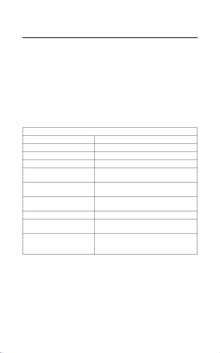
Taking Care of the Unexpected
227
If Your Engine Quits or Won’t Start
Proper operation and maintenance can prevent starting and engine performance
problems. In many cases, the cause of the problem may be a simple operational
oversight.
If you have a problem starting the engine – or experience poor engine
performance – the following information may help you. If you can’t correct the
problem, see your dealer.
If your motorcycle won’t start, listen as you press the start button. If you don’t
hear the starter motor turning, refer
to the Starter motor doesn’t operate
symptom. If you can hear the starter motor working normally, refer to the
Starter motor works, but the engine won’t start symptom.
SYMPTOM: Starter motor doesn’t operate.
POSSIBLE CAUSE WHAT TO DO
ignition switch OFF Turn the ignition switch ON.
engine stop switch OFF Turn the engine stop switch to RUN.
transmission not in neutral Shift into neutral.
reverse (RVS) switch ON Push the reverse (RVS) switch to the
OFF position.
side stand down (when
transmission not in neutral)
Put the transmission in neutral or raise the
side
stand and pull the clutch lever in.
blown fuse Replace with a new fuse of the same
rating (page 244).
battery lead loose Tighten the battery lead.
low (or dead) battery Charge the battery (page 212). If charging
doesn’t help, see your dealer.
faulty starter motor If all possible causes are negative, the
starter motor may be faulty. See your
dealer.

SYMPTOM: Starter motor works, but the engine won’t start.
POSSIBLE CAUSE WHAT TO DO
out of fuel Fill the fuel tank.
flooded engine See F
looded Engine (page 72).
loose or unconnected
spark plug caps
Install the spark plug caps securely. If the
engine still won’t start, see your dealer.
loose battery cables Tighten the battery terminal bolts.
weak battery Charge the battery (page 212). If charging
doesn’t help, see your dealer.
SYMPTOM: Engine starts, but stalls as you shift into gear.
POSSIBLE CAUSE WHAT TO DO
side stand down Raise the side stand. Start again.
228
Taking Care of the Unexpected
If Your Engine Quits or Won’t Start
SYMPTOM: Engine starts, but runs poorly.
POSSIBLE CAUSE WHAT TO DO
idles roughly, too fast,
stalls
See your dealer.
overheating Check the coolant temperature gauge.
Refer to If Your Engine Overheats, page
241.
low oil pressure Check the low oil pressure indicator.
Refer to If the Low Oil Pressure Indicator
Lights, page 243.
runs erratically, misfires May damage catalytic converters.
See your dealer.
blubbers (rich fuel mixture) See your dealer.
sooty exhaust (rich fuel
mixture)
See your dealer.
detonates or pings under
load
If applicable, switch to the recommended
octane gasoline (page 172) or change
your brand of gasoline. If the problem
persists, see your dealer.
afterfires (backfires) May damage catalytic converters.
See your dealer.
pre-ignition (runs on after
ignition switched OFF)
May damage catalytic converters.
See your dealer.
Taking Care of the Unexpected
229
If Your Engine Quits or Won’t Start
230
Taking Care of the Unexpected
If You Have a Flat Tire
A flat tire is always unwelcome, especially if you are far from help. If you think
you are losing air, or you hit a pothole or hard object, pull safely to the side of
the road so you can inspect the tires and assess the situation. (Be sure to park on
a firm, level surface and use the center stand for support.) You should examine
the tire treads and sidewalls for foreign objects or damage. If you find a tire that
has been punctured or damaged, you have two options.
Option 1:
Have Your Motorcycle Transported
If a tire has a major puncture or a cut in the tread or sidewall, or the bead has
come loose from the rim, there is probably not much you can do except have
your motorcycle transported to your dealer or other qualified service facility.
Even with a simple puncture, this may be the safest and least troublesome
solution. For transporting instructions, see page 222.
Option 2:
Make a Temporary Roadside Repair
If a tire has only a minor nail puncture and is not completely flat, you may be
able to make an emergency repair that could allow you to continue riding to
where you can get the tire replaced or permanently repaired.
Riding your motorcycle with a
temporary tire repair can be
risky. If the temporary repair
fails, you can crash and be
seriously injured or killed.
If you must ride with a temporary
tire repair, ride slowly and
carefully and do not exceed 30
mph (50 km/h) until the tire is
permanently repaired or
replaced.

Taking Care of the Unexpected
231
If You Have a Flat Tire
Due to the uncertainty of any temporary repair, you should ride slowly (not over
30 mph, 50 km/h) and carefully (preferably without a passenger or cargo) until
the tire is replaced or permanently repaired. Stop frequently and check the air
pressure. If the tire is losing pressure, it may be unsafe to continue riding. As the
tire gets low, it will affect the handling of your motorcycle (especially with a
passenger and cargo), and it may overheat and blow out.
Types of Temporary Repairs
The following types of temporary repairs generally require a source of air to
inflate the tire. Possible sources include CO
2 cartridges or cans of compressed
air designed to inflate a tire.
For more information on tire repair, see page 205.
• Inflate the tire: Tubeless tires have some self-sealing ability if they are
punctured and the result is usually just a slow leak. If this is the case, you can
try inflating the tire to see if it will hold air pressure. If you can see a nail or
other object embedded in the tire tread, do not remove it at this time.
• Plug the hole: The idea here is to do something to temporarily stop the leak.
If you have a tubeless tire repair kit, you can pull out the nail and try inserting
an external plug in the puncture. Follow the instructions that came with the
repair kit and be sure to inflate the tire to the correct pressure.
Using a puncture-repairing agent can damage the TPMS sensors, causing the
TPMS indicator to turn on. Have you motorcycle checked by your dealer as
soon as possible.
Use caution to not damage the TPMS sensor if an internal plug patch must be
used to repair the tire. If you have a tire professionally repaired at a non- Honda
facility, we recommend that you have the work checked by your dealer. TPMS
wheels require special handling when changing the tire. Failure to follow the
proper tire replacement procedure can result in damage to the TPMS sensor.

232
Taking Care of the Unexpected
If You Have a Flat Tire
Should You Repair or Replace a Tire?
We strongly recommend that you replace, not permanently repair, any tire that is
punctured or damaged, even if the tire has only a minor puncture. For a full
discussion of repairs and replacement, see page 205.
Emergency Front Wheel Removal/Installation
Refer to Safety Precautions on page 154.
We recommend wheel removal be done only by your dealer or another qualified
mechanic. Do not attempt to remove the wheel on your own. Wheel removal
requires mechanical skill and professional tools.
Removal
1. Park your motorcycle on a firm, level surface.
2. Raise the front wheel off the ground by placing a support block under the
engine, being careful to avoid contact with the exhaust pipe and front lower
cover.
3. Remove the parts in sequence, according to the order in the illustration.
• When removing and installing the wheel, be careful not to damage the
sensor and pulser ring. (Models equipped with ABS)
• To avoid damage to the brake hose during removal, support the caliper
assembly so that it doesn’t hang from the hose. Do not twist the brake
hose.
• Avoid getting grease, oil, or dirt on the disc or pad surfaces. Any
contamination can cause poor brake performance or rapid pad wear after
reassembly.
• Avoid depressing the brake lever and brake pedal when the wheel is off the
motorcycle. This will force the caliper pistons out of the cylinders. The
result will be a loss of brake fluid. If this occurs, the brake system will
require service.
See your dealer for this service.
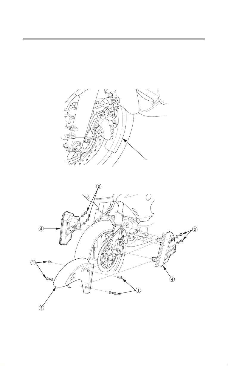
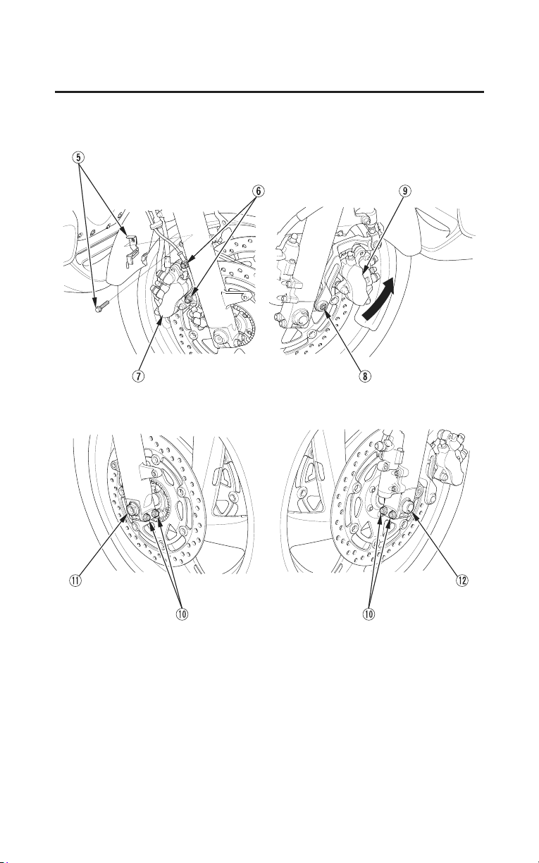
(Models equipped with ABS)
234
Taking Care of the Unexpected
If You Have a Flat Tire
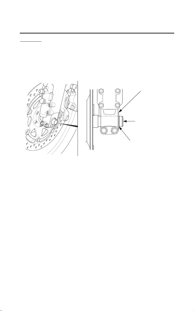
Taking Care of the Unexpected
235
If You Have a Flat Tire
Installation
1. Install the side collars in the wheel and position it between the fork legs.
Insert the front axle shaft from the left side, through the left fork leg and
wheel hub.
2. Align the index line of the front axle shaft with the recessed surface of the
fork leg.
recessed surface
front axle shaft
index line
3. Tighten the front axle pinch bolts on the left fork leg to the specified torque:
16 lbf·ft (22 N·m , 2.2 kgf·m)
4. Tighten the front axle bolt to the specified torque:
44 lbf·ft (59 N·m , 6.0 kgf·m)
5. Install the brake caliper assembly onto the fork leg.
To avoid damaging the brake pads while installing the brake caliper
assembly, carefully fit the brake disc between the pads.
6. Install the right caliper fixing bolts and left caliper socket bolt and tighten to
the specified torque:
23 lbf·ft (31 N·m , 3.2 kgf·m)
• Use new right caliper fixing bolts
f
and left caliper socket bolt
h
when
installing the brake calipers.
(cont’d)
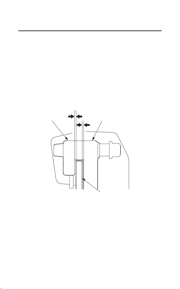
236
Taking Care of the Unexpected
If You Have a Flat Tire
7. Operate the front brake and pump the fork several times. Check for free
wheel rotation after the brake is released. Recheck the wheel if the brake
drags or the wheel does not rotate freely.
8. If the clearances between each surface of the brake disc and the brake bracket
(not the brake pads) are symmetrical, follow the next step.
If the clearances are not symmetrical, loosen the left axle pinch bolts and pull
the left fork outward or push inward to adjust the clearance. Then follow the
next step.
9. Tighten the front axle pinch bolts on the right fork leg to the specified torque:
16 lbf·ft (22 N·m , 2.2 kgf·m)
• Visually check that the clearances between each surface of the brake disc
and the brake bracket (not
the brake pads) are symmetrical.
brake bracket brake bracket
brake disc

Taking Care of the Unexpected
237
If You Have a Flat Tire
10.After installing the wheel, apply the brake lever AND brake pedal several
times, then recheck both discs for caliper holder to disc clearance. Do not
operate the motorcycle without adequate clearance.
• Check for free wheel rotation after the brake lever and brake pedal are
released. Recheck the wheel if the brake drags or if the wheel does not
rotate freely.
• After installing the wheel, operate the brake lever AND brake pedal
several times until you feel pressure. You must restore pressure from
BOTH the lever AND the pedal because this motorcycle is equipped with
Dual CBS (Linked Braking System).
• Verify proper brake operation before riding.
11. Remove the protective tapes from the front wheel.
12.Reassemble the removed parts in the reverse order of removal.
If a torque wrench is not used for installation, see
your dealer as soon as
possible to verify proper assembly. Improper assembly may lead to loss of
braking capability.

238
Taking Care of the Unexpected
If You Have a Flat Tire
Emergency Rear Wheel Removal/Installation
Refer to Safety Precautions on page 154.
We recommend wheel removal be done only by your dealer or another qualified
mechanic. Do not attempt to remove the wheel on your own. Wheel removal
requires mechanical skill and professional tools.
Removal
1. Park your motorcycle on its center stand on a firm, level surface.
2. Remove the parts in sequence, according to the order in the illustration.
• Avoid getting grease, oil, or dirt on the disc or pad surfaces. Any
contamination can cause poor brake performance or rapid pad wear after
reassembly.
• When removing and installing the wheel, be careful not to damage the
sensor and pulser ring. (Models equipped with ABS)
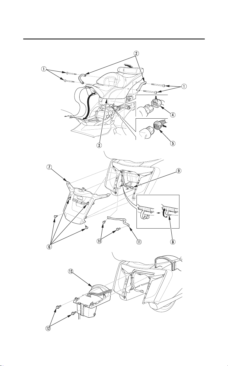
Taking Care of the Unexpected
239
If You Have a Flat Tire
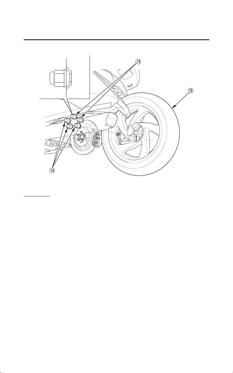
240
Taking Care of the Unexpected
If You Have a Flat Tire
Installation
1. Reassemble the removed parts in the reverse order of removal.
2. Tighten the rear wheel nuts to the specified torque:
80 lbf·ft (108 N·m , 11.0 kgf·m)
3. After installing the wheel, apply the brake several times and then check if the
wheel rotates freely. Recheck the wheel if the brake drags or if the wheel does
not rotate freely.
If a torque wrench is not used for installation, see your dealer as soon as
possible to verify proper assembly. Improper assembly may lead to loss of
braking capability.

Taking Care of the Unexpected
241
If Your Engine Overheats
Normally, the needle on your temperature gauge will rise to a point about
midway between C (cold) and H (hot) and then level off. Hot weather may
cause the needle to rise higher than normal. So will temporary stress such as
climbing a hill. If you’re stuck in stop-and-go traffic, the needle may climb
some, but the radiator fan is designed to prevent overheating. Be aware of these
variations as you monitor the gauge.
• If your vehicle is operated at sustained speeds between 10 and 15 miles per
hour
in high ambient temperature conditions, you may experience high
temperature gauge readings.
• If the temperature gauge rises, shifting to second gear or altering your speed
(either
faster or slower) may reduce the temperature reading. If the indicator
reaches the red zone, as soon as it is safe to do so, pull over and let the engine
idle until the indicator drops.
Continuing to ride with an overheated engine can cause serious engine damage.
• A steaming engine indicates a coolant leak. Shut the engine off and wait until
the steaming stops. Look for a leak, but don’t touch the engine or radiator
system. Let everything cool off first.
• If there’s no obvious problem, leave the engine on so the fan and coolant
circulating system can continue working. Monitor the temperature gauge.
The needle may drop to the normal range after a brief stop with no load on
the engine.
• Check the radiator fan.
If the fan is not working, turn the engine off. Open the fuse box (page 244)
and check the radiator fan fuse. If the fuse is blown, replace it with the proper
(same rating) spare fuse. Start the engine. If the needle climbs to the red zone
and stays there, turn the engine off.
If the radiator fan is working, visually check the coolant level in the reserve
tank, located behind the left engine side cover. It isn’t necessary to touch the
radiator system.
(cont’d)

242
Taking Care of the Unexpected
If Your Engine Overheats
• If the reserve tank is low or empty, don’t ride without adding coolant (page
183). After adding coolant, turn the engine on and check the temperature
gauge.
If the needle doesn’t drop, do not ride. The engine needs repair. Transport
your motorcycle to a dealer (page 222).
If the temperature drops to normal, check the coolant level. If it has gone
down, add
more coolant.
If you are able to resume riding, continue to monitor the gauge frequently.
If there’s a mild leak, you can ride for awhile, carefully watching the gauge. Be
prepared to stop and add more coolant or water. If the leak is bad, transport your
motorcycle to your dealer (page 222).

Taking Care of the Unexpected
243
If the Low Oil Pressure Indicator Lights
If you check your engine oil level regularly, you should never see the low oil
pressure indicator comes on while riding. Normally, it will only light
momentarily when you turn the ignition switch ON. Occasionally, it may flicker
at or near idling speed.
Low oil pressure may be caused by an oil leak, a low oil level, or some problem
in the engine’
s lubrication system.
If the indicator comes on while you’re riding, don’t ignore it. Pull safely to the
side of the road. If possible, pull the clutch lever in and coast to a stop. Stop the
engine as soon as it’s safe to do so.
Continuing to ride with low oil pressure can cause serious engine damage.
• Check for an oil leak.
• Then check the oil level. If necessary, add the recommended oil (page 178) to
the upper level mark. If you must leave your motorcycle to get oil, secure it
as much as possib
le.
• After adding oil, start the engine, and check that the low oil pressure indicator
goes off. Check for a possible leak.
If the indicator goes off and there is no leak –– resume riding. If there is a
leak –– do not ride the motorcycle until the leak is repaired by your dealer.
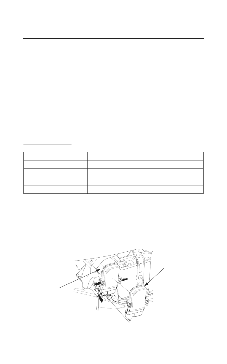
244
Taking Care of the Unexpected
If a Fuse Blows
All of the electrical circuits on your motorcycle have fuses to protect them from
damage caused by excess current flow (short circuit or overload).
If something electrical on your motorcycle stops working, the first thing you
should check for is a blown fuse.
Determine from the chart on the circuit fuse box cover which fuse or fuses
control that component. Check those fuses first, but check all the fuses before
looking elsewhere for another possible cause of the problem. Replace any
blown fuses and check component operation.
• The circuit fuse box (including spare fuses) is located behind the left side
cover.
•The main fuse is located in the fuse box.
Recommended Fuses
main fuse A 30 A
main fuse B 120 A
speed limiter fuse 60 A
external amplifier fuse 40 A
other fuses 30 A, 20 A, 15 A, 10 A, 5 A
1. To prevent an accidental short circuit, turn the ignition switch OFF before
checking or replacing the fuses.
2. Remove the left side cover (page 167).
3. Remove the fuse box cover.
LEFT SIDE
fuse box
fuse box cover

Taking Care of the Unexpected
245
If a Fuse Blows
Main Fuse Access:
4. Check the two main fuses (A & B) to see if they are blown.
To replace main fuses (A & B), see your dealer for this service.
Speed Limiter Fuse Access:
5. Check the speed limiter (reverse system) fuse to see if it’s blown, see your
dealer for this service.
Circuit Fuses Access:
6. To check or replace a circuit fuse, pull the old fuse out of its retaining clips
with the
fuse remove
r. Look for a burned wire inside the fuse. If the fuse is
blown, replace it with a spare fuse of the same rating.
If you do not have a replacement fuse with the proper rating for the circuit,
install one with a lower rating.
Replacing a fuse with one that has a higher rating greatly increases the chance
of damage to the electrical system.
External Amplifier Fuse Access:
7. To replace the external amplifier fuse, see your dealer for this service.
(cont’d)
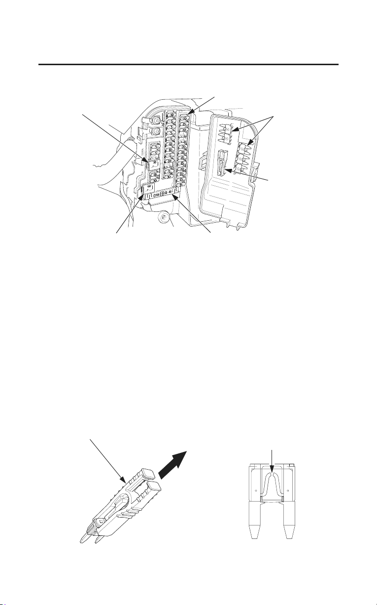
246
Taking Care of the Unexpected
If a Fuse Blows
LEFT SIDE
main fuse A
circuit fuses
spare fuses
fuse remover
speed limiter fuse main fuse B/external amplifier fuse
8. Close the fuse box cover.
9. Install the left side cover.
If you do not have a spare fuse and you cannot ride the motorcycle without
fixing the proble
m, take a fuse of the same rating or a lower rating from one of
the other circuits that you can do without temporarily.
If you replace a blown fuse with a spare fuse that has a lower rating, replace the
fuse with the correct rating as soon as you can. Also remember to replace any
spare fuses that were installed.
If the replacement fuse of the same rating burns out in a short time, there is
probably a serious electrical problem on your motorcycle. Leave the blown fuse
in that circuit and have your motorcycle checked by your dealer.
fuse remover
blown fuse

Taking Care of the Unexpected
247
If You Crash
Personal safety is your first priority after a crash. If you or anyone else has been
injured, take time to assess the severity of the injuries and whether it is safe to
continue riding. Call for emergency assistance if needed. Also follow applicable
laws and regulations if another person or vehicle is involved in the crash.
If you decide that you are capable of riding safely, first evaluate the condition of
your motorcycle.
If the engine is still running, turn it off and look it over
carefully; inspect it for fluid leaks, check the tightness of critical nuts and bolts,
and secure such parts as the handlebar, control levers, brakes, and wheels.
If there is minor damage, or you are unsure about possible damage, ride slowly
and cautiously. Sometimes, crash damage is hidden or not immediately
apparent, so you should have your motorcycle thoroughly checked at a qualified
service facility as soon as possible. Also, be sure to have your dealer check the
frame and suspension after any serious crash.
If your motorcycle cannot be ridden, see Transporting Your Motorcycle,
page 222.
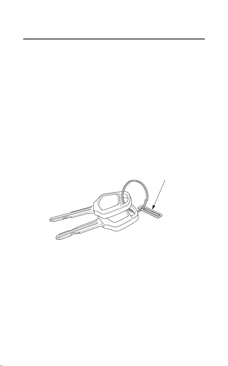
248
Taking Care of the Unexpected
If You Lose Your Key
You should receive a key number plate with your keys.
Store the spare key and number plate in a safe location. You’ll need this number
to have a duplicate key made.
A lost key won’t be a problem if you take preventative action. Store one
duplicate key in a safe place at home and carry a second duplicate in your
wallet.
If you lose your key and aren’t carrying a duplicate, either get your spare or
have one made. If you don’t know your key number, call the dealer where you
purchased your Honda. They may have it listed in their records. If they don’t,
transport your motorcycle to them or the nearest dealer. The dealer will
probably have to remove the ignition switch assembly to find the key number so
they can make a key for you.
key number plate

Taking Care of the Unexpected
249
If Your Battery Is Low (or Dead)
Jump starting is not recommended, especially if you use an automobile battery.
The greater amperage of an automobile battery when the car engine is running
can damage your motorcycle’s electrical system.
Bump starting is also not recommended.
If you can’t charge the battery or it appears unable to hold a charge, contact your
dealer.

Technical Information
251
Technical Information
This section contains dimensions, capacities, and other technical data, plus
information on government requirements and how to break-in your motorcycle.
Vehicle Identification ..................................................................................... 252
Specifications ................................................................................................. 254
Break-in Guidelines ....................................................................................... 260
Tire Pressure Monitoring System (TPMS) Explanation ................................. 261
Emission Control Systems ............................................................................. 263
Catalytic Converters....................................................................................... 267
Oxygenated Fuels........................................................................................... 268
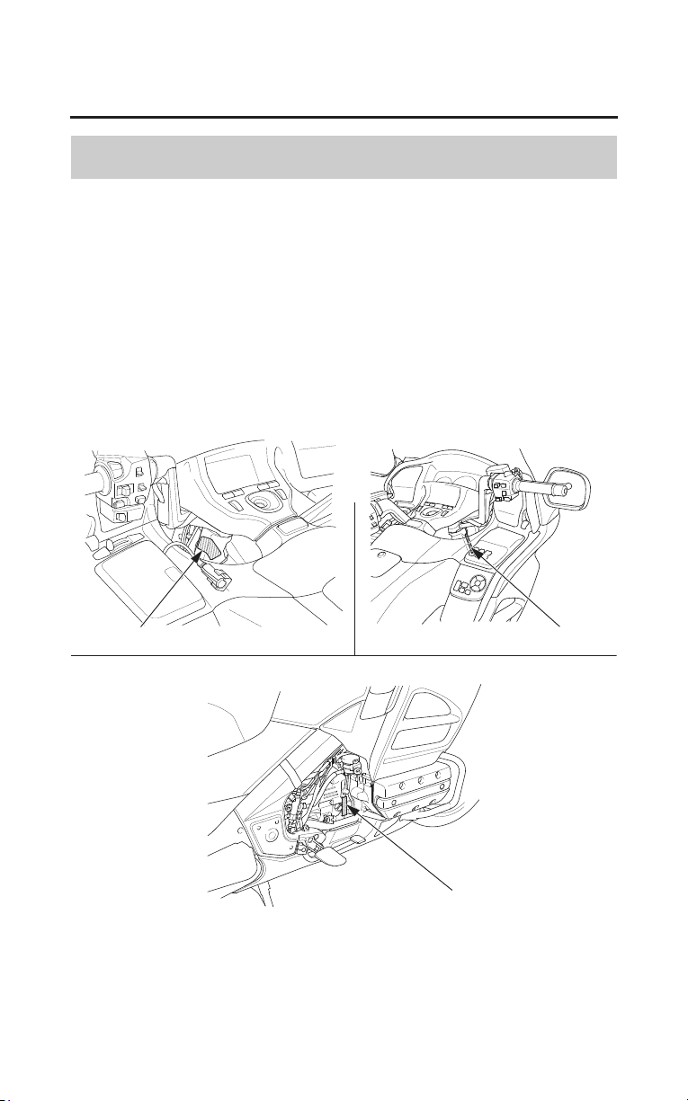
252
Technical Information
Vehicle Identification
Serial Numbers
The VIN and engine serial number are required when you register your
motorcycle. They may also be required when ordering replacement parts. You
may record these numbers in the Quick Reference section at the rear of this
manual.
The VIN (vehicle identification number) is stamped on the right side of the
steering head and also
appears on the Safety Certification Label attached to the
left side of the steering head.
The engine number is stamped on the right side of the crankcase.
LEFT SIDE RIGHT SIDE
RIGHT SIDE
VIN
VIN
engine number
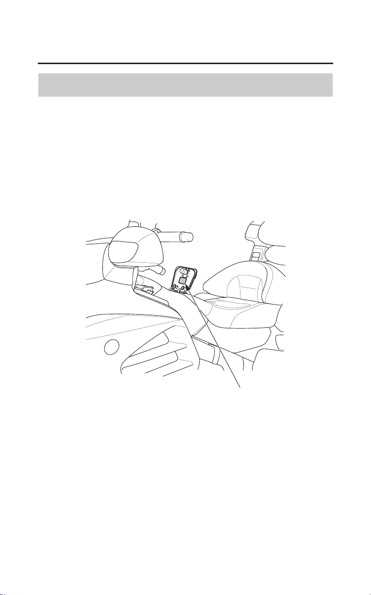
Technical Information
253
Vehicle Identification
Color Label & Code
The color label is attached inside the fuel filler compartment lid.
The color code is helpful when ordering replacement parts. You may record the
color and code in the Quick Reference section at the rear of this manual.
color label
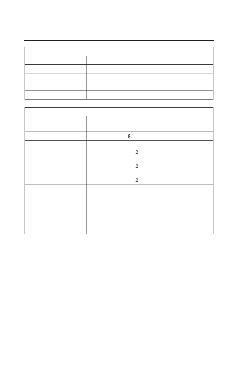
Dimensions
overall length 103.5 in (2,630 mm)
overall width 37.2 in (945 mm)
overall height 57.3 in (1,455 mm)
wheelbase 66.5 in (1,690 mm)
ground clearance 4.9 in (125 mm)
Fuel & Lubricants
fuel recommendation unleaded gasoline, pump octane number of 86
or high
er
fuel tank capacity
6.6 US gal (25
)
engine oil capacity after disassembly:
4.9 US qt (4.6 )
after draining:
3.8 US qt (3.6
)
after draining & oil filter change:
3.9 US qt (3.7
)
engine oil
recommendation
API Service Classification SG or higher
except oils labeled as energy conserving or
resource conserving on the circular API service
label, SAE 10W-30, JASO T 903 standard MA,
Pro Honda GN4 4-stroke oil (USA & Canada)
or Honda 4-stroke oil, or an equivalent
mo
torcycle oil
254
Technical Information
Specifications
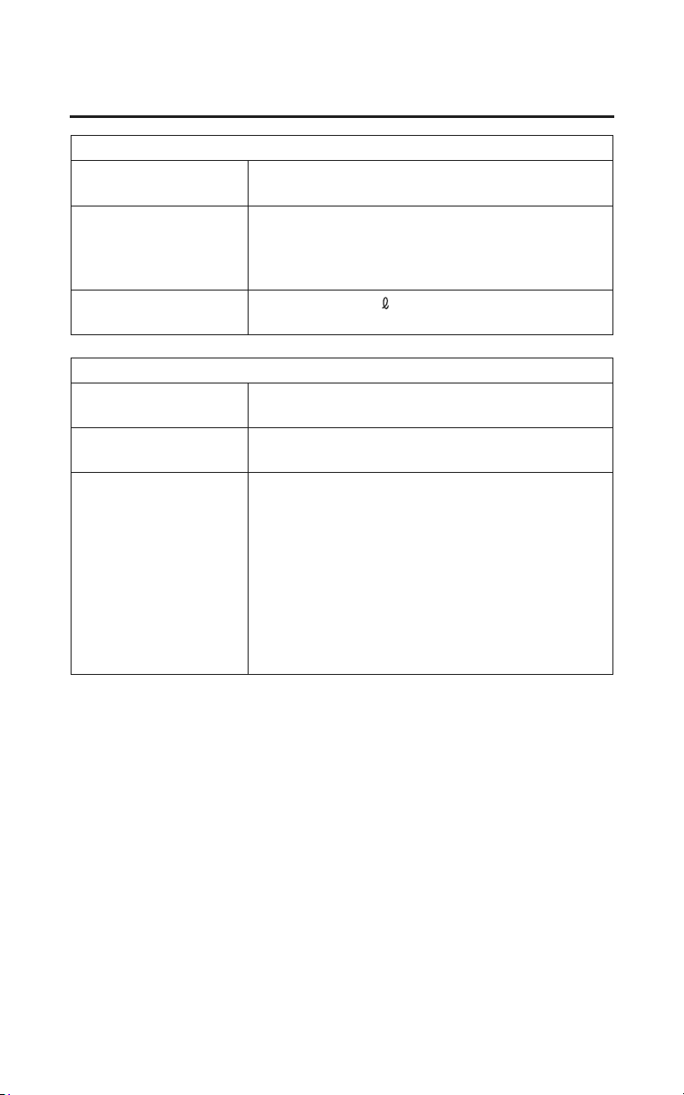
Fuel & Lubricants (Cont’d)
final drive oil
capacity
after draining:
4.1 US oz (120 cm
3
)
cooling system,
recommendation
Pro Honda HP Coolant or an equivalent high
quality ethylene glycol antifreeze containing
corrosion protection inhibitors specifically
recommended for use in aluminum engines
cooling system,
capacity
4.06 US qt (3.84
)
Capacities
passenger
capacity
Operator and one passenger
maximum weight
capacity
410 lb (186 kg)
rider, passenger, all cargo and accessories
cargo capacity travel trunk: 20.0 lb (9.0 kg)
each saddlebag: 20.0 lb (9.0 kg)
fairing pocket: 4.5 lb (2.0 kg)
each trunk side pocket: 1.0 lb (0.5 kg)
shelter case (Models not equipped
with Airbag): 6.6 lb (3.0 kg)
total of all cargo (Models not equipped
with Airbag): 72 lb (33 kg)
total of all cargo (Models equipped with
Airbag): 66 lb (30 kg)
Technical Information
255
Specifications
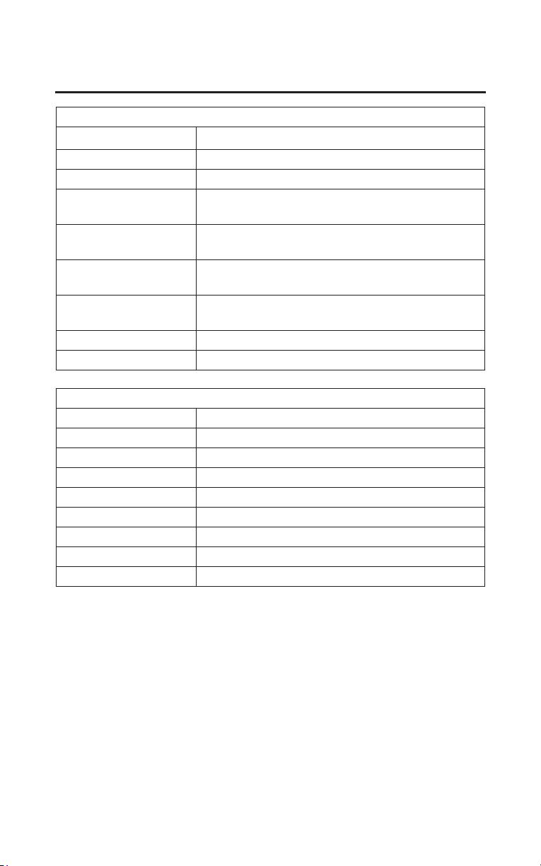
Engine Specifications
displacement
111.8 cu-in (1,832 cm
3
)
bore & stroke 2.91 × 2.80 in (74.0 mm × 71.0 mm)
compression ratio 9.8 : 1
spark plug
(standard)
BKR6E-11 (NGK) or
K20PR-U11 (DENSO)
spark plug (cold
cl
imate)
BKR5E-11 (NGK) or
K16PR-U11 (DENSO)
spark plug (high
speed riding)
BKR7E-11 (NGK) or
K22PR-U11 (DENSO)
valve clearance
(cold)
intake 0.006 in (0.15 mm)
exhaust 0.009 in (0.22 mm)
spark plug gap 0.039 – 0.043 in (1.00 – 1.10 mm)
idle speed 700 ± 70 rpm (No adjustment)
Power Transmission
primary reduction 1.591
secondary reduction 1.028
final reduction 2.750
gear ratio, 1st 2.375
2nd 1.454
3rd 1.068
4th 0.843
OD 0.685
final drive shaft
256
Technical Information
Specifications
Chassis & Suspension
caster 29°15’
trail 4.3 in (109 mm)
tire size, front 130/70R18M/C 63H
BRIDGESTONE G709 RADIAL
tire size, rear 180/60R16M/C 74H
BRIDGESTONE G704 RADIAL
tire type radial, tubeless
tire pressure, front
(cold)
36 psi (250 kPa, 2.50 kgf/cm
2
)
tire pressure, rear
(cold)
41 psi (280 kPa, 2.80 kgf/cm
2
)
Electrical
battery GYZ20L
12 V – 20 Ah (10HR)
generator 1.2 kW/5,000 rpm
Technical Information
257
Specifications
Lights
headlight 12 V – 55 W × 2 (high)
12 V – 55 W × 2 (low)
brake/tail light 12 V – 21/5 W × 4
turn signal lights 12 V – 21/5 W × 2 (front)
12 V – 21 W × 2 (rear)
license light 12 V – 5 W
instrument light LED
neutral indicator LED
turn signal indicator LED
high beam indicator LED
low oil pressure
indicator
LED
side stand indicator LED
low fuel indicator LED
PGM-FI malfunction
in
dicator lamp (MIL)
LED
reverse indicator LED
overdrive indicator LED
CRUISE ON indicator LED
CRUISE SET
in
dicator
LED
tire pressure
monitoring system
(TPMS) indicator
LED
low tire pressure
indicator
LED
ABS indicator
(models equipped
with ABS)
LED
AIRBAG indicator
(models equipped
with Airbag)
LED
258
Technical Information
Specifications
Fuses
main A 30 A
main B 120 A
speed limiter fuse 60 A
external amplifier
fu
se
40 A
other fuses 30 A, 20 A, 15 A, 10 A, 5 A
Torque Specifications
engine oil drain bolt 25 lbf·ft (34 N·m , 3.5 kgf·m)
engine oil filter 19 lbf·ft (26 N·m , 2.7 kgf·m)
front wheel axle bolt 44 lbf·ft (59 N·m , 6.0 kgf·m)
right front wheel
cal
iper fixing bolts
23 lbf·ft (31 N·m , 3.2 kgf·m)
left front wheel
caliper socket bolt
23 lbf·ft (31 N·m , 3.2 kgf·m)
front wheel axle
pinch bolts
16 lbf·ft (22 N·m , 2.2 kgf·m)
rear wheel nuts 80 lbf·ft (108 N·m , 11.0 kgf·m)
final drive oil drain
bolt
15 lbf·ft (20 N·m , 2.0 kgf·m)
Technical Information
259
Specifications

260
Technical Information
Break-in Guidelines
Help assure your motorcycle’s future reliability and performance by paying
extra attention to how you ride during the first 300 miles (500 km).
During this period, avoid full-throttle starts and rapid acceleration.
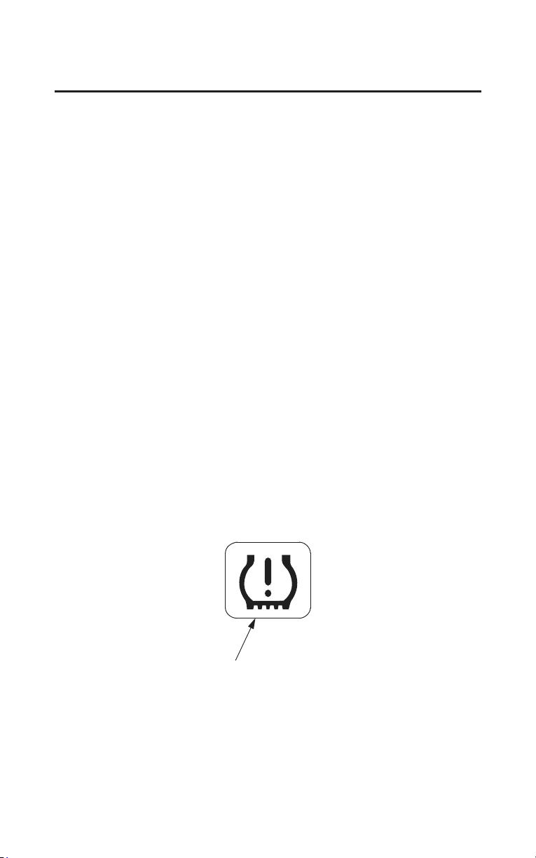
Technical Information
261
Tire Pressure Monitoring System
(TPMS) Explanation
Both tires should be checked monthly when cold, and inflated to the inflation
pressure recommended by the vehicle manufacturer on the tire information
label.
(If your vehicle has different tires than those indicated on the vehicle tire
information label, you should determine the proper tire inflation pressure for
those tires.)
As an added safety feature, your vehicle has been equipped with a tire pressure
monitoring system (TPMS) that illuminates a low tire pressure indicator when
one or more of your tires significantly under-inflated.
Accordingly, when the low tire pressure indicator illuminates, you should stop
and check your tires as soon as possible, and inflate them to the proper pressure.
Riding on a significantly under-inflated tire causes the tire to overheat and can
lead to
tire failure. Under-inflation also reduces fuel efficiency and tire tread
life, and may affect the vehicle’s handling and stopping ability.
Please note that the TPMS is not a substitute for proper tire maintenance, and it
is the rider’s responsibility to maintain correct tire pressure, even if under-
inflation has not reached the level to trigger illumination of the TPMS low tire
pressure indicator.
low tire pressure indicator
262
Technical Information
Tire Pressure Monitoring System
(TPMS) Explanation
Your vehicle has also been equipped with a TPMS indicator to indicate when
the system is not operating properly. The TPMS indicator displays the symbol
‘‘TPMS’’ when illuminated.
When the TPMS indicator is illuminated, the system may not be able to detect
or signal low tire pressure as intended.
TPMS malfunctions may occur for a variety of reasons, including the
installation of replacement or alternate tires or wheels on the vehicle that
prevent the TPMS from functioning properly.
Always check the TPMS indicator after replacing one or more tires or wheels on
your vehicle to ensure
that the replacement or alternate tires and wheels allow
the TPMS to continue to function properly.
TPMS indicator
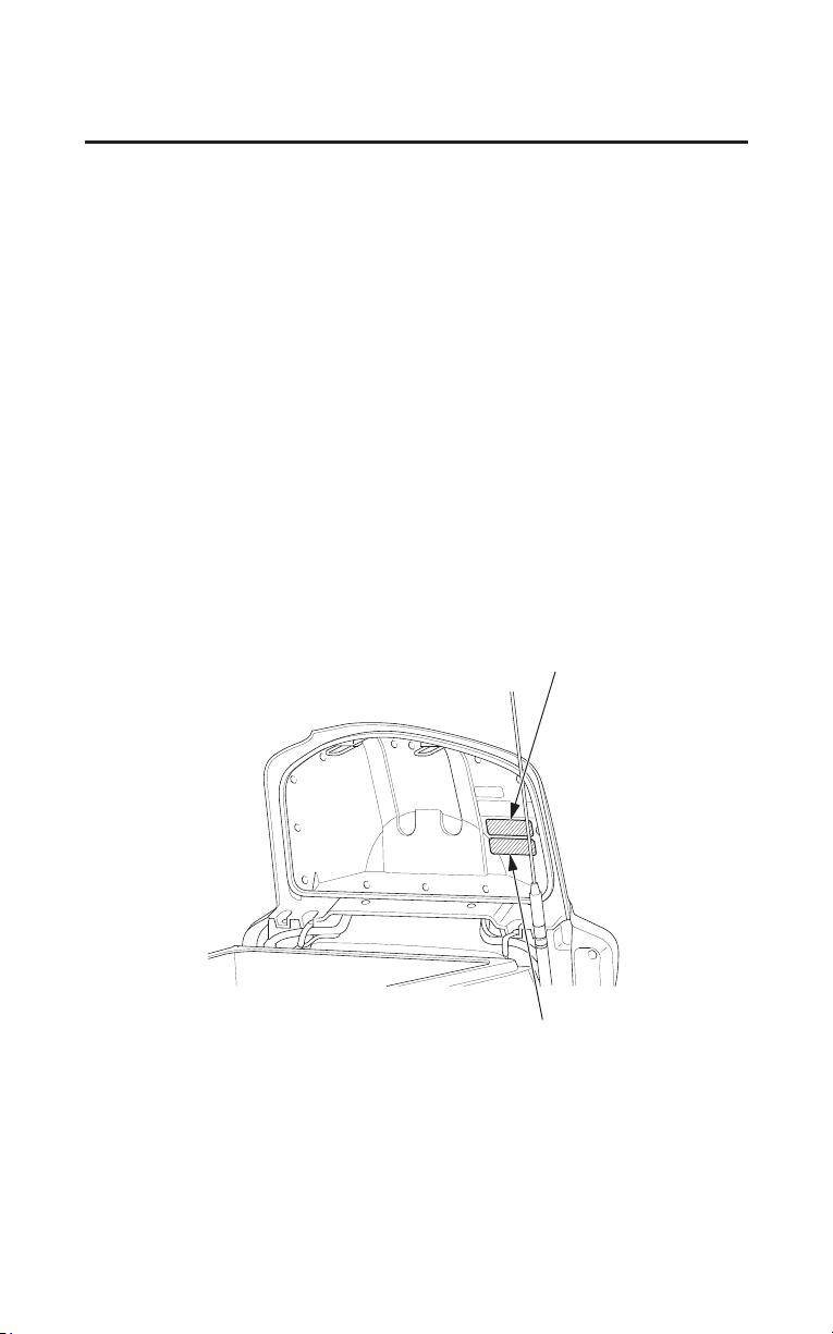
Technical Information
263
Emission Control Systems
Exhaust Emission Requirements
The U.S. Environmental Protection Agency (EPA), the California Air Resources
Board (CARB), and Environment Canada (EC) require that your motorcycle
comply with applicable exhaust emissions standards during its useful life, when
operated and maintained according to the instructions provided.
Noise Emission Requirements
The EPA also requires that motorcycles built after January 1, 1983 comply with
applicable noise emission standards for one year or 3,730 miles (6,000 km) after
the time of sale to the ultimate purchaser, when operated and maintained
according to the instructions provided.
Warranty Compliance
Compliance with the terms of the Distributor’s Warranties for Honda
Motorcycle Emission Control Systems is necessary in order to keep the
emissions system warranty in effect. (USA only)
vehicle emission control
information label
vehicle emission control
information label
(Canada only)
The Vehicle Emission Control Information label is attached inside the trunk lid.

264
Technical Information
Emission Control Systems
Source of Exhaust Emissions
The combustion process produces carbon monoxide (CO), oxides of nitrogen
(NOx) and hydrocarbons (HC). Control of hydrocarbons and oxides of nitrogen
is very important because, under certain conditions, they react to form
photochemical smog when subjected to sunlight. Carbon monoxide does not
react in the same way, but it is toxic.
Honda Motor Co., Ltd. utilizes various systems to reduce carbon monoxide,
oxides of nitrogen and hydrocarbons.
Exhaust Emission Control System
The exhaust emission control system includes a PGM-FI system, two three-way
catalytic con
verters, a secondary air injection system, an ignition timing control
system, and two heated oxygen sensors or two air fuel ratio sensors.
No adjustment to these systems should be made although periodic inspection of
the comp
onents is recommended.
PGM-FI System
The PGM-FI system has four subsystems: Air Intake, Engine Control, Fuel
Control, and Exhaust Control.
The Engine Control Module (ECM) uses various sensors to determine how
much air is going into the engine. It then controls how much fuel is injected
under all operating conditions.
Ignition Timing Control System
The system constantly adjusts the ignition timing, reducing the amount of HC,
CO and NOx produced.
Secondary Air Injection System
The secondary air injection system introduces filtered air into the exhaust gases
in the exhaust p
ort. The secondary air injection system helps improve emission
control performance.
Three-Way Catalytic Converters
The three-way catalytic converters are in the exhaust system. Through chemical
reactions, they convert HC, CO, and NOx in the engine’s exhaust to carbon
dioxide (CO
2), nitrogen (N), and water vapor.

Technical Information
265
Emission Control Systems
Evaporative Emission Control System
This motorcycle complies with the requirements of the California Air Resources
Board (CARB) evaporative emission regulations. Fuel vapor from the fuel tank
is directed into the charcoal canister and air cleaner where it is adsorbed and
stored while the engine is stopped. When the engine is running and the purge
control solenoid valve is open, fuel vapor in the charcoal canister and air cleaner
is drawn into the engine through the throttle body.
Crankcase Emission Control System
The engine is equipped with a closed crankcase system to prevent discharging
crank
case
emissions into the atmosphere. Blow-by gas is returned to the
combustion chamber through the air cleaner and the intake manifold.

266
Technical Information
Emission Control Systems
Problems That May Affect Motorcycle Exhaust Emissions
If you are aware of any of the following symptoms, have the vehicle inspected
and repaired by your dealer.
Symptoms:
1. Hard starting or stalling after starting
2. Rough idle
3. Misfiring or backfiring during acceleration
4. After-burning (backfiring)
5. Poor performance (driveability) and poor fuel economy
Noise Emission Control System
TAMPERING WITH THE NOISE CONTROL SYSTEM IS PROHIBITED:
U. S. federal law prohibits, or Canadian provincial laws may prohibit the
following acts
or the causing thereof: (1) The removal or rendering inoperative
by any person, other than for purposes of maintenance, repair or replacement, of
any device or element of design incorporated into any new vehicle for the
purpose of noise control prior to its sale or delivery to the ultimate purchaser or
while it is in use; or (2) the use of the vehicle after such device or element of
design has been removed or rendered inoperative by any person.
AMONG THOSE ACTS PRESUMED TO CONSTITUTE TAMPERING ARE
THE FOLLOWING
ACTS:
• Removal of, or puncturing the muffler, baffles, header pipes or any other
component which conducts exhaust gases.
• Removal of, or puncturing of any part of the intake system.
• Lack of proper maintenance.
• Removing or disabling any emissions compliance component, or replacing
any compliance
component with a non-compliant component.
Fuel Permeation Emission Control System
This vehicle complies with the Fuel Permeation Emission Control regulations of
the U.S. Environmental Protection Agency (EPA), the California Air Resources
Board (CARB), and Environment Canada (EC). The fuel tank, fuel hoses, and
fuel vapor charge hoses used on this vehicle incorporate fuel permeation control
technologies. Tampering with the fuel tank, fuel hoses, or fuel vapor charge
hoses to reduce or defeat the effectiveness of the fuel permeation technologies is
prohibited by federal regulations.

Technical Information
267
Catalytic Converters
This motorcycle is equipped with two three-way catalytic converters. Each
catalytic converter contains precious metals that serve as catalysts, promoting
chemical reactions to convert the exhaust gasses without affecting the metals.
The catalytic converters act on HC, CO, and NOx. Replacement parts must be
original Honda parts or equivalents.
The catalytic converters must operate at high temperature for the chemical
reactions to take place. They can set fire to any combustible materials that come
near them. Park your motorcycle away from high grasses, dry leaves, or other
flammables.
Defective catalytic converters contribute to air pollution, and can impair your
engine’s performance. Follow these guidelines to protect your motorcycle’s
catalytic converters.
• Always use unleaded gasoline. Even a small amount of leaded gasoline can
contaminate the catalyst metals, making the catalytic converters ineffective.
• Keep the engine in good running condition.
A poorly running engine can cause the catalytic converter to overheat causing
damage to the converter or the motorcycle.
• If your engine is misfiring, backfiring, stalling, or otherwise not running
properly, stop riding and turn off the engine. Have your motorcycle serviced
as soon as possible.

268
Technical Information
Oxygenated Fuels
Some conventional gasolines are being blended with alcohol or an ether
compound. These gasolines are collectively referred to as oxygenated fuels. To
meet clean air standards, some areas of the United States and Canada use
oxygenated fuels to help reduce emissions.
If you use an oxygenated fuel, be sure it is unleaded and meets the minimum
octane rating requirement.
Before using an oxygenated fuel, try to confirm the fuel’s contents. Some states/
provinces require this information to be posted on the pump.
The following are the EPA-approved percentages of oxygenates:
ETHANOL (ethyl or grain alcohol) up to 10% by Volume
You may use gasoline containing up to 10% ethanol by volume. Gasoline
containing ethanol may be marketed under the name ‘‘Gasohol’’.
METHANOL (methyl or wood alcohol) up to 5% by Volume
You may use gasoline containing methanol containing up to 5% methanol by
volume as long as it also contains cosolvents and corrosion inhibitors to
protect the fuel system. Gasoline containing more than 5% methanol by
volume may cause starting and/or performance problems. It may also damage
metal, rubber, and plastic parts of your fuel system.
If you notice any undesirable operating symptoms, try another service station or
switch to another brand of gasoline.
Fuel system damage or performance problems resulting from the use of an
oxygenated fuel containing more than the percentages of oxygenates mentioned
above are not covered under warranty.
Oxygenated fuels can damage paint and plastic. Be careful not to spill fuel when
filling the fuel tank. Wipe up any spills immediately.
Oxygenated fuels can damage paint and plastic. Damage caused by spilled fuel
is not covered by warranty.

Consumer Information
269
Consumer Information
This section contains information on your warranty and how to get an official
Honda Service Manual.
Authorized Manuals....................................................................................... 270
Warranty Coverage......................................................................................... 271
Warranty Service............................................................................................ 272
Contacting Honda........................................................................................... 273
Your Honda Dealer......................................................................................... 274
The Honda Rider’s Club (USA only)............................................................. 275
Reporting Safety Defects (USA only)............................................................ 276
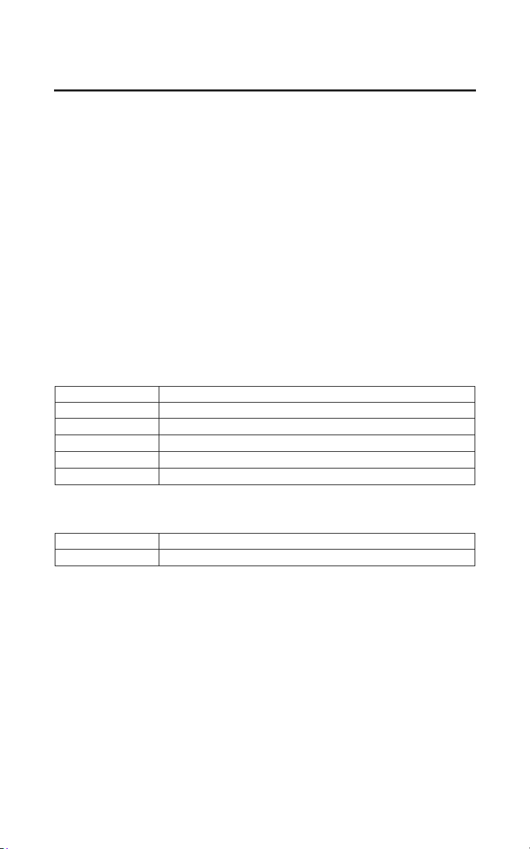
270
Consumer Information
Authorized Manuals
The Service Manual used by your authorized dealer is available from your
Honda dealer or Helm, Inc. (USA only, Canada: See your dealer to order
authorized manuals.)
Also available but not necessary to service your model is the Honda Common
Service Manual which explains theory of operation and basic service
information for various systems on Honda motorcycles, scooters, ATVs, SxSs,
and PWCs.
The Winter Storage Guide in conjunction with the Owner’s Manual and Service
Manual can help you prepare your Honda motorcycle, scooter, ATV, and SxS
for winter storage.
These Honda manuals are written for the professional technician, but most
mechanically capable owners should find them easy to use if they have the
proper tools and observe proper safety standards. Special Honda tools are
necessary for some procedures.
Publication Item No. Description
61MCA64 2016 GL1800 Service Manual/ETM
61CSM00 Common Service Manual
S9507 Winter Storage Guide
31MJK630 2016 GL1800 Owner’s Manual
31MJKT30 2016 GL1800 Navigation System Manual
Publication Item No. Description
31MJKU30 2016 GL1800 Owner’s Manual Airbag Supplement
(Also available for Models equipped with Airbag)
Order On-Line: www.helminc.com
Order Toll Free: 1-888-CYCLE93 (1-888-292-5393)
(NOTE: For Credit Card Orders Only)
Monday – Friday 8:00 AM – 6:00 PM EST

Consumer Information
271
Warranty Coverage
Your new Honda is covered by these warranties:
• Motorcycle Limited Warranty
• Emission Control System Warranty
• Noise Control Warranty (USA only)
There are responsibilities, restrictions, and e
xclusions which apply to these
warranties. Please read the Warranties Booklet given to you by your Honda
dealer at the time of purchase. Be sure to keep your Honda owner’s card with
your Warranties Booklet.
Canada: Please refer to the Warranty Booklet posted on our website at
www.honda.ca.
It is important to realize that your warranty applies to defects in material or
workmanship of your Honda. Your warranty coverage does not apply to normal
wear or deterioration associated with using the motorcycle.
Your warranty coverage will not be voided if you choose to perform your own
maintenance. However, you should have the proper tools and service
information and be mechanically qualified. Failures that occur due directly to
improper maintenance are not covered.
Almost all of your warranty coverage can be extended through the Honda
Protection Plan (USA only). For more information, see your Honda dealer.

272
Consumer Information
Warranty Service
Please remember that recommended maintenance interval servicing is not
included in your warranty coverage. Additionally, your warranty does not apply
to the normal wear of items (such as brakes, tires, etc.).
If you believe you have a problem with your motorcycle, call the service
department of your Honda dealer. Make an appointment for an inspection and
diagnosis. Remember, as the owner of the motorcycle, you will be asked to
authorize that inspection. Your dealer will give you the results of the inspection.
If the problem is covered under warranty, your dealer will perform the warranty
repairs for you.
If you have questions about warranty coverage or the nature of the repair, it is
be
st to talk to the Service Manager of your Honda dealer.
Sometimes, in spite of the best intentions of all concerned, a misunderstanding
may occur. If you aren’t satisfied with your dealer’s handling of the situation,
we suggest you discuss your problem with the appropriate member of the
dealership’s management team. If the problem has already been reviewed with
the Service Manager, Parts Manager, Sales Manager, etc., contact the Owner of
the dealership or their designated representative.

Consumer Information
273
Contacting Honda
Your owner’s manual was written to cover most of the questions you might ask
about your Honda. Any questions not answered in the owner’s manual can be
answered by your dealer. If your dealer doesn’t have the answer right away, they
will get it for you.
If you have a difference of opinion with your dealer, please remember that each
de
alership is independently owned and operated. That’s why it’s important to
work to resolve any differences at the dealership level.
If you wish to comment on your experiences with your Honda or with your
dealer, please send your comments to the following address:
Motorcycle Division, American Honda Motor Co., Inc., P.O. Box 2200,
Torrance, CA 90509-2200, mailstop: 100-4C-7B, telephone: (866) 784-1870.
Canada: Honda Canada Inc., Customer Relations Dept, 180 Honda Boulevard,
Markham, O
ntario L6C 0H9, telephone: (888) 946-6329, facsimile: (877) 939-
0909.
E-mail: [email protected]
Please include the following information in your letter:
• name, address, and telephone number
• product model, year, and VIN
• date of purchase
• dealer name and address
We will likely ask your dealer to respond, or possibly acknowledge your
co
mments directly.

274
Consumer Information
Your Honda Dealer
Once you purchase your new Honda, get familiar with the organization of your
Honda dealer so you can utilize the full range of services available.
The service department is there to perform regular maintenance and unexpected
repairs. It has the latest available service information from Honda. The service
department will also handle warranty inspections and repairs.
The parts department offers Honda Genuine Parts, Pro Honda products, Honda
Genuine Accessories (USA only), and Honda accessories and products (Canada
only). The same quality that went into your Honda can be found in Honda
Genuine replacement parts. You’ll also find comparable quality in the
accessories and products available from the parts department.
The sales department offers the Honda Protection Plan to extend almost all of
your warranty coverage (USA only).
Your Honda dealer can inform you about competition and other riding events in
your area. You’ll also find that your dealer is a source of information about
safety training available in your local area and the Honda Rider’s Club of
America (USA only).
We’re sure you’ll be as pleased with the service your Honda dealer continues to
provide
after the sale as you are with the quality and dependability of your
Honda.

Consumer Information
275
The Honda Rider’s Club (USA only)
The Honda Rider’s Club of America (HRCA) sponsors local riding chapters at
Authorized Honda Dealerships across the country.

276
Consumer Information
Reporting Safety Defects (USA only)
If you believe that your vehicle has a defect which could cause a crash or could
cause injury or death, you should immediately inform the National Highway
Traffic Safety Administration (NHTSA) in addition to notifying American
Honda Motor Co., Inc.
If NHTSA receives similar complaints, it may open an investigation, and if it
finds
that a safety defect exists in a group of vehicles, it may order a recall and
remedy campaign. However, NHTSA cannot become involved in individual
problems between you, your dealer, or American Honda Motor Co., Inc.
To contact NHTSA, you may call the Vehicle Safety Hotline toll-free at
1-888-327-4236 (TTY: 1-800-424-9153); go to http://www.safercar.gov; or
write to: Administrator, NHTSA, 1200 New Jersey Avenue, SE.,
Washington, DC 20590.
You can also obtain other information about motor vehicle safety from
http://www.safercar.gov.
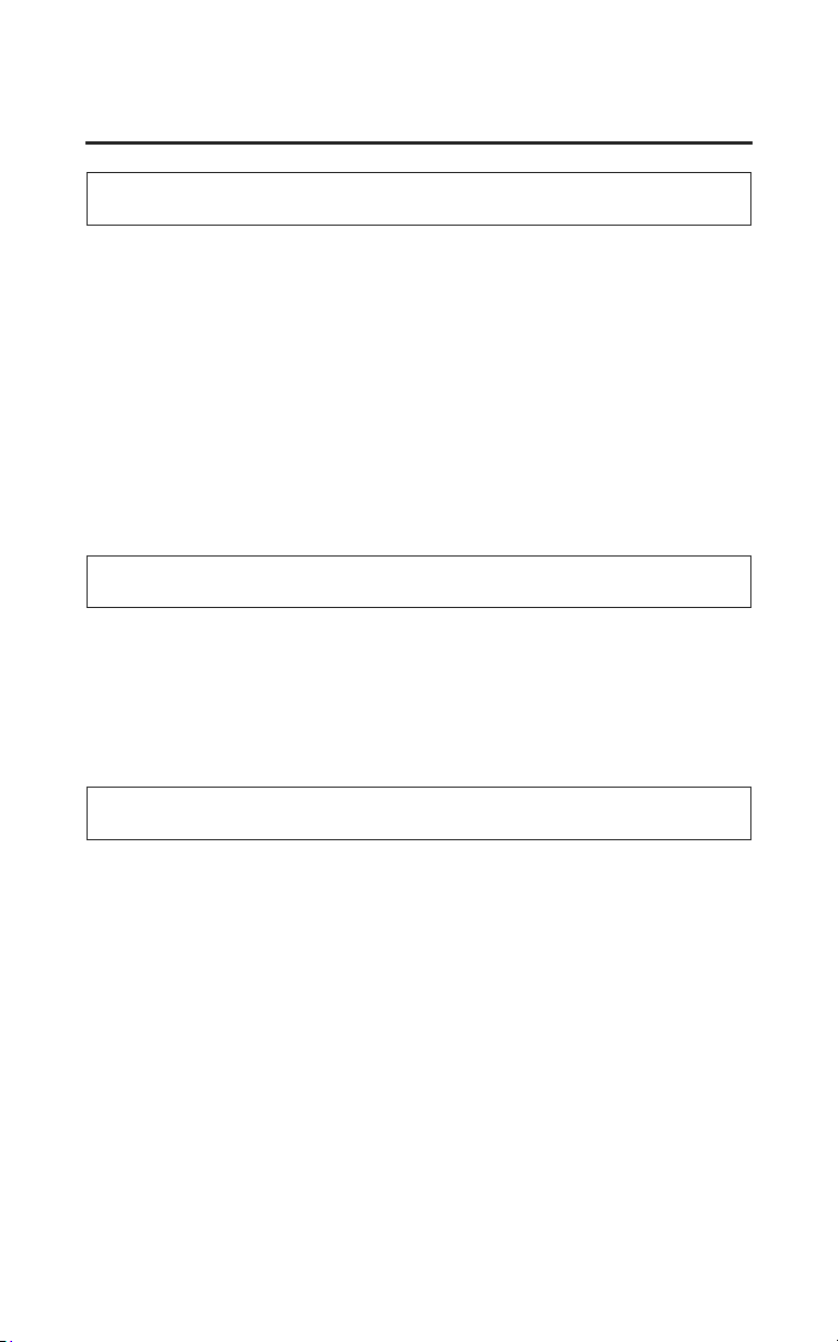
278
Index
Index
A
ABS indicator light ..................................................................................... 19, 83
accessories........................................................................................................... 4
accessory (ACC) terminal ................................................................................. 67
air pressure, tires .............................................................................................202
air temperature meter ........................................................................................ 31
American Honda, contacting...........................................................................275
antenna, radio ................................................................................................. 114
Anti-Lock Brake System (ABS) .......................................................................80
apparel, protective ............................................................................................. 44
appearance care ............................................................................................... 213
audio systems ....................................................................................................95
authorized manuals.......................................................................................... 270
B
battery..............................................................................................................209
brakes,
fluid .............................................................................................................197
pad wear ......................................................................................................199
braking............................................................................................................... 78
break-in guidelines.......................................................................................... 260
C
capacity, fuel ................................................................................................... 173
care, appearance .............................................................................................. 213
catalytic converters.......................................................................................... 267
cleaning, appearance care................................................................................ 213
clutch system................................................................................................... 188
color label........................................................................................................ 253
combined ABS .................................................................................................. 80
comfort and convenience adjustment................................................................ 61
compartment,
owner’s manual ...........................................................................................165
tool kit ......................................................................................................... 164
Index
279
Index
consumer information ..................................................................................... 269
controls & features ............................................................................................ 35
coolant .............................................................................................................182
coolant temperature gauge ..........................................................................15, 20
crankcase breather........................................................................................... 185
cruise control..................................................................................................... 91
customer service.............................................................................................. 273
D
defects, reporting safety .................................................................................. 276
digital clock adjustment ....................................................................................30
drive, final ....................................................................................................... 186
E
emission control systems.................................................................................263
engine,
flooded .......................................................................................................... 72
low oil press
ure ........................................................................................... 243
number ........................................................................................................ 252
oil ................................................................................................................ 175
overheats ..................................................................................................... 241
pinging ........................................................................................................ 172
starting...........................................................................................................71
stop switch .................................................................................................... 36
stopping......................................................................................................... 73
won’t start
................................................................................................... 227
environment.....................................................................................................223
F
fairing pocket .................................................................................................... 59
final drive oil................................................................................................... 186
flat tire ............................................................................................................. 230
flooded engine...................................................................................................72
(cont’d)
280
Index
Index
fuel,
gauge ....................................................................................................... 15, 20
oxygenated .................................................................................................. 268
recommendation..........................................................................................172
tank capacity ............................................................................................... 173
fuses................................................................................................................. 244
G
gasohol ............................................................................................................ 268
gasoline ........................................................................................................... 172
gauges & indicators........................................................................................... 15
H
hazard switch..................................................................................................... 39
headlight beam adjustment................................................................................ 40
headlight dimmer switch...................................................................................38
heater,
handgrip ........................................................................................................ 65
seat ................................................................................................................ 66
helmet holder.....................................................................................................88
high beam indicator..................................................................................... 15, 19
Honda,
contacting.................................................................................................... 273
dealer...........................................................................................................274
Rider’s Club ................................................................................................ 275
Honda Service Manual.................................................................................... 270
horn button ........................................................................................................38
I
identification, vehicle......................................................................................252
ignition cut-off system,
bank angle sensor.......................................................................................... 73
side stand.......................................................................................................71
ignition switch................................................................................................... 35
indicators ...........................................................................................................15
inspection, pre-ride............................................................................................47
iPod
®
...............................................................................................................135
K
Index
281
Index
key, lost ........................................................................................................... 248
kit, tool ............................................................................................................ 164
L
labels, safety........................................................................................................ 6
lamp check ........................................................................................................ 16
limit, weight ......................................................................................................50
load limits.......................................................................................................... 50
loading guidelines ............................................................................................. 51
lock, steering ..................................................................................................... 87
low tire pressure indicator................................................................................. 84
M
maintenance,
component locations ................................................................................... 161
importance...................................................................................................152
periodic ....................................................................................................... 155
record .......................................................................................................... 160
safety ...........................................................................................................153
schedule.......................................................................................................156
manual, authorized .......................................................................................... 270
manual, service................................................................................................ 270
maximum weight limit ......................................................................................50
modifications....................................................................................................... 5
multi information display..................................................................................21
N
numbers, serial ................................................................................................
252

O
282
Index
Index
odometer............................................................................................................ 26
oil,
engine.......................................................................................................... 175
final drive .................................................................................................... 186
low pressure ................................................................................................ 243
operation component locations .........................................................................
12
overdrive indicator ...................................................................................... 15, 17
overheat, engine .............................................................................................. 241
owner’s manual storage...................................................................................165
oxygenated fuels.............................................................................................. 268
P
parking............................................................................................................... 87
pinging, engine................................................................................................ 172
plugs, spark ..................................................................................................... 190
pocket,
fairing............................................................................................................ 59
pockets,
trunk side....................................................................................................... 60
pre-load, rear suspension spring...................................................................... 193
pre-ride inspection............................................................................................. 47
problems, unexpected......................................................................................225
protective apparel.............................................................................................. 44
R
radio antenna ................................................................................................... 114
radio,
AM/FM ....................................................................................................... 115
XM
®
............................................................................................................ 119
remote transmitter ............................................................................................. 55

Index
283
Index
removal,
clip............................................................................................................... 171
cylinder head side cover.............................................................................. 169
engine side cover......................................................................................... 168
front lower cover......................................................................................... 170
side cover .................................................................................................... 167
reverse,
button ............................................................................................................ 35
riding in......................................................................................................... 76
system indicator ......................................................................................15, 17
reporting safety defects ...................................................................................276
rider training.................................................................................................. 2, 46
Rider’s Club, Honda........................................................................................
275
riding,
bad weather ................................................................................................... 94
basic operation .............................................................................................. 69
clothing ......................................................................................................... 44
safety ............................................................................................................... 2
safety precautions..........................................................................................
70
with cruise control......................................................................................... 91
with passenger or cargo.................................................................................90
S
saddlebag........................................................................................................... 52
safety,
important precautions.................................................................................. 154
lables ............................................................................................................... 6
reporting defects..........................................................................................276
riding precautions..........................................................................................70
schedule, maintenance..................................................................................... 156
serial numbers ................................................................................................. 252
service,
customer......................................................................................................273
manuals ....................................................................................................... 270
warranty ......................................................................................................272
shifting gears .....................................................................................................74
side stand......................................................................................................... 208
side stand ignition cut-off system...................
.....
..............................................71
(cont’d)

284
Index
Index
side stand indicator......................................................................................15, 19
spark knock .....................................................................................................172
spark plugs ...................................................................................................... 190
specifications...................................................................................................254
speedometer................................................................................................. 15, 16
stand, side........................................................................................................ 208
start/reverse button............................................................................................ 37
starting,
engine............................................................................................................ 72
troubleshooting ...........................................................................................
227
steering lock ......................................................................................................87
stop switch, engine ............................................................................................36
stopping engine ................................................................................................. 73
storage,
motorcycle................................................................................................... 220
owner’s manual ...........................................................................................165
suspension,
rear spring pre-load ..................................................................................... 193
switch,
audio control ......................................................................................... 38, 101
cruise control........................................................................................... 37, 92
engine stop .................................................................................................... 36
hazard............................................................................................................
39
headlight dimmer ..........................................................................................38
ignition .......................................................................................................... 35
rear suspension spring pre-load adjustment.......................................... 41, 193
reverse..................................................................................................... 37, 76
turn signal......................................................................................................38
T
tachometer ................................................................................................... 15, 16
theft-prevention tips
.......................................................................................... 89
tires,
air pressure .................................................................................................. 202
flat ............................................................................................................... 230
replacing...................................................................................................... 206
tire pressure monitoring system (TPMS) .......................................................... 83
tire pressure monitoring system (TPMS) explanation .................................... 261
tire pressure monitoring system (TPMS) indicator...........................................85
Index
285
Index
tool kit ............................................................................................................. 164
training, rider................................................................................................. 2, 46
transporting your motorcycle .......................................................................... 222
travel trunk ........................................................................................................52
tripmeter ............................................................................................................26
trouble, unexpected .........................................................................................
225
troubleshooting, starting..................................................................................227
trunk side pockets.............................................................................................. 60
trunk, travel ....................................................................................................... 52
turn signal indicators...................................................................................15, 17
U
USB flash drive............................................................................................... 140
V
vehicle identification no. (VIN) ....
..................................................................252
ventilation.................................................................................................... 63, 64
W
warranty,
coverage ......................................................................................................271
extended ...................................................................................................... 271
service .........................................................................................................272
washing your motorcycle ................................................................................214
weight limit .......................................................................................................50
wheels,
front removal...............................................................................................232
rear removal ................................................................................................ 238
windscreen height adjustment levers ................................................................ 62
Quick Reference
Quick Reference
The following is a brief, but important collection of information you need to
know about your Honda. You’ll also find space to record important notes.
The engine of your Honda can be the most expensive component to repair.
Proper maintenance, especially the use of the recommended fluids and filters,
prevents premature wear and damage.
Frequent causes of costly repairs are:
• Engine oil –– insufficient quantity, improper oil.
• Air cleaner –– dirty, leaking because of improper installation (poor seal).
Record important information on the following page:
VIN
Engine No.
Color Label
Owner’s Name
Address
City/State
Phone
Dealer’s Name
Address
City/State
Phone
Service Mgr.

Quick Reference
Quick Reference
Scheduled
Maintenance
Regular: every 4,000 miles (6,400 km)
Pre-ride
Inspection
Check the following items each time before you ride
(page 47): tires & wheels, leaks, loose parts, lights,
throttle, brakes, indicators, gauges.
Periodic Checks Check the following items monthly (page 155): tires &
wheels, fluids, lights, fuses, nuts & bolts.
Fuel/Capacity unleaded gasoline, pump octane number 86 or higher
6.6 US gal (25
)
Engine Oil API Service Classification SG or higher except oils
labeled as energy conserving or resource conserving
on
the circular API serv
ice label,
SAE 10W-30, JASO T 903 standard MA,
Pro Honda GN4 4-stroke oil (USA & Canada) or
Honda 4-stroke oil, or an equivalent motorcycle oil
Maximum Weight
Capacity
410 lb (186 kg)
rider, passenger, all cargo and accessories
maximun of all cargo (Models not equipped with
A
irbag): 72 lb (33 kg)
maximum of all cargo (Models equipped with Airbag):
66 lb (30 kg)
Tires front: 130/70R18M/C 63H
BRIDGESTONE G709 RADIAL
rear: 180/60R16M/C 74H
BRIDGESTONE G704 RADIAL
type: r
adial, tubeless
Tire Pressure
(cold)
front: 36 psi (250 kPa, 2.50 kgf/cm
2
)
rear: 41 psi (280 kPa, 2.80 kgf/cm
2
)

Quick Reference
Quick Reference
Spark Plugs standard:
BKR6E-11 (NGK) or K20PR-U11 (DENSO)
cold climate (below 5°C, 41°F):
BKR5E-11 (NGK) or K16PR-U11 (DENSO)
high speed riding:
BKR7E-11 (NGK) or K22PR-U11 (DENSO)
Coolant ethylene glycol antifreeze (silicate-free) for aluminum
e
ngines in 50/50 solution with Pro Honda HP Coolant
or an equivalent distilled water
Fuses main A: 30 A
main B: 120 A
speed limiter: 60 A
external amplifier: 40 A
other: 30 A, 20 A, 15 A, 10 A, 5 A
Final Drive Oil Hypoid Gear Oil SAE 80
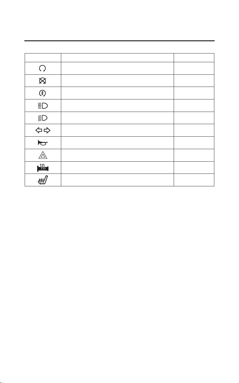
Quick Reference
Quick Reference
These symbols are used in Controls & Features section:
SYMBOL COMPONENT SEE PAGE
RUN – engine stop switch 36
OFF – engine stop switch 36
START/REVERSE button 37
HI – headlight dimmer switch 38
LO – headlight dimmer switch 38
turn signal switch 38
horn button 38
hazard switch 39
handgrip heater switch 65
seat heater switch 66

