36V/48V | 10A
Version 1.0
ROVER
BOOST
Maximum Power-Point Tracking Boost Charge Controller
01
General Safety Information
Battery Safety Information
Charger Location and Installation Information
Important Safety Instructions
Please save these instructions.
This manual contains important safety, installation, and operating instructions for the
charge controller. The following symbols are used throughout the manual to indicate
potentially dangerous conditions or important safety information.
Remove all sources of power, photovoltaic and battery before servicing or installing.
Make sure connections going into and from the controller are tight and secure.
WARNING - EXPLOSION HAZARD
NEVER charge a frozen battery
Working in the vicinity of lead-acid batteries is dangerous. Batteries produce explosive
gasses during normal battery operation.
To reduce risk of battery explosion, follow these instructions and those published by battery
manufacturer and manufacturer of any equipment you intend to use in vicinity of battery.
Refer installation and servicing to qualified service personnel. High voltage is present inside
unit. Incorrect installation or use may result in risk of electric shock or fire. No user
serviceable parts in this unit.
Do not short the battery; do not let the positive and negative terminals of the battery contact
each other.
The controller employs components that tend to produce arcs or sparks. NEVER install in
battery compartment or in the presence of explosive gases.
Overcharging and excessive gas precipitation may damage battery plates and activate
material shedding on them. Please review battery charging specifications before
connecting your battery.
Do NOT allow water to enter the charge controller, irreversible damage may occur.
Protect all wiring from physical damage, vibration, and excessive heat.
Ensure all terminating connections are clean and tight to prevent arcing and overheating.
Do NOT expose the controller to rain or snow
NOTE
CAUTION
WARNING
Indicates a potentially dangerous condition. Use extreme caution when
performing this task
Indicates a critical procedure for safe and proper operation of the controller
Indicates a procedure or function that is important to the safe and proper
operation of the controller

02
Table of Contents
General Information
Product Description
Product Overview
03
03
04
07
Included Components
Identification of Parts
Dimensions
04
06
Optional Components
Installation
Mounting Recommendations
Wiring
Battery Wiring
Solar Panel Wiring
Grounding
Connecting the Battery Voltage Sensor (RVSCC)
07
08
09
10
10
16
16
17
17
18
18
19
27
Connecting the Temperature Sensor (RTSCC)
08
13
15
Recommended Gauge and Ring Terminal Sizes
Auto Recognition and Toggle
Operation
Set the Battery Type
LED Indicators
MPPT Technology
22
23
23
Communication Ports
Host Mode Communication
Connecting to a 48V Smart LFP Battery
26
24
Paralleling 2 Rover Boosts w/ a 48V Smart Battery
Paralleling 2 Rover Boosts w/ Non-Lithium
Electronic Protections and Troubleshooting
31Maintenance
32
Technical Specifications
33
Battery Charging Parameters

03
Product Description
General Information
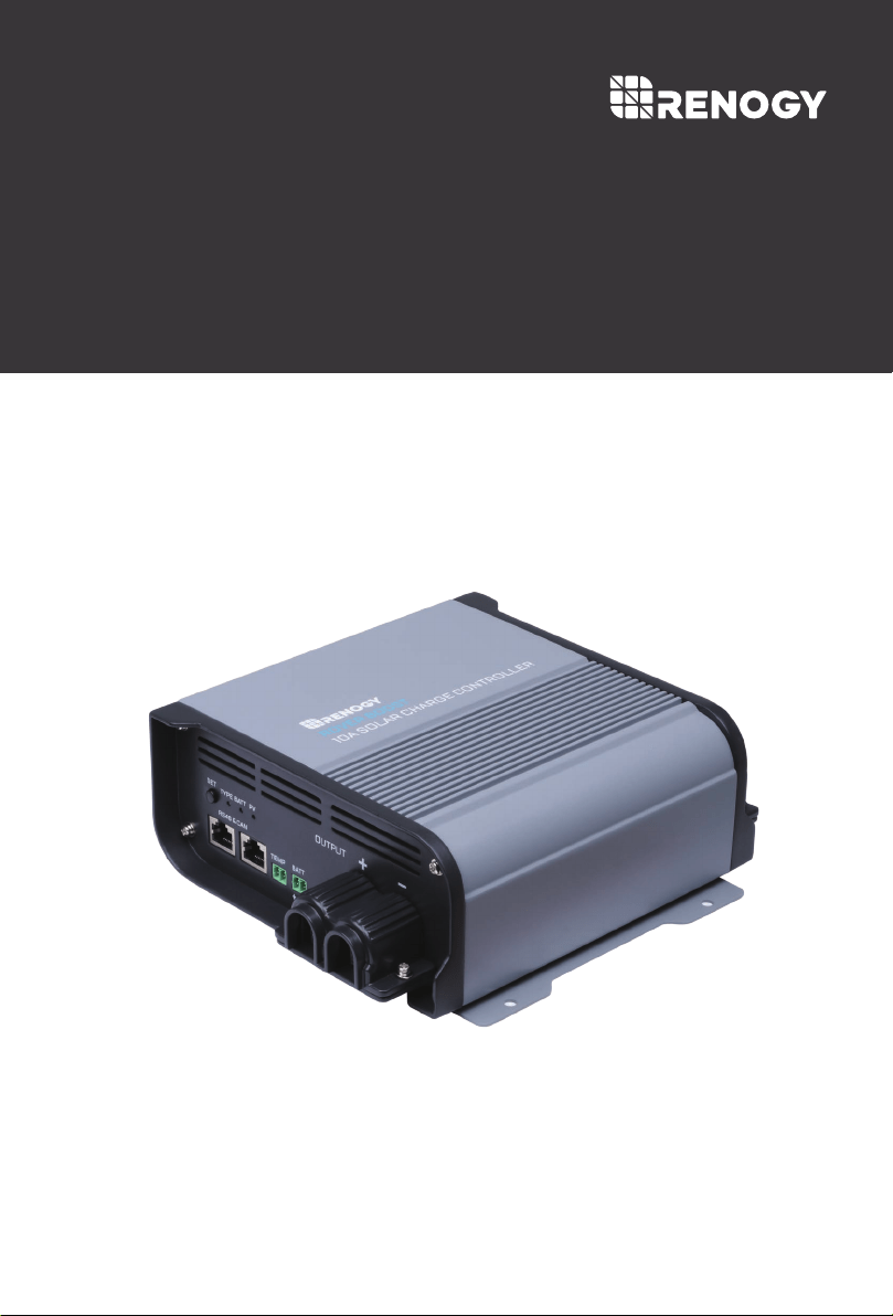
The all-new Rover Boost controller is a 10Amp Maximum Power Point Tracking (MPPT) charge
controller engineered to charge a 36V or 48V battery bank from voltage typically found in only
1-2, 36-cell solar modules. Featuring 4-stage battery charging (Bulk, Boost, Float, and
Equalization), the Rover Boost is pre-set to be compatible with AGM, Gel, Flooded, and Lithium
batteries, and even includes custom battery settings. The Rover Boost is packed with
numerous battery bank, controller, and solar electronic protections for peace of mind and an
optimized system you can trust.
36V/48V Automatic System Recognition of Lead Acid Batteries.
Self-adaptable to a wide solar panel input voltage for appropriate battery charging.
Multi-Function LEDs displaying system information and identifying any errors.
RS485 communication port for monitoring using the Bluetooth module and Renogy DC
Home App.
CAN communication port synchronizes the battery information for smart charging.
Advanced MPPT Technology with minimum 99% tracking efficiency and above 90%
charge conversion efficiency.
4 Pre-set battery charge profiles include AGM, Gel, Flooded, and Lithium as well as a
custom mode for a wide variety of applications.
Multiple battery bank, controller, and solar electronic protections including over-charge
protection, reverse polarity protection, and more.
Key Features
04
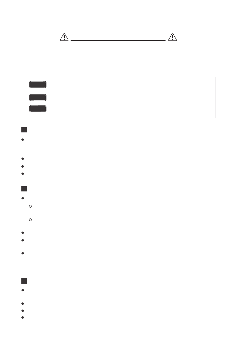
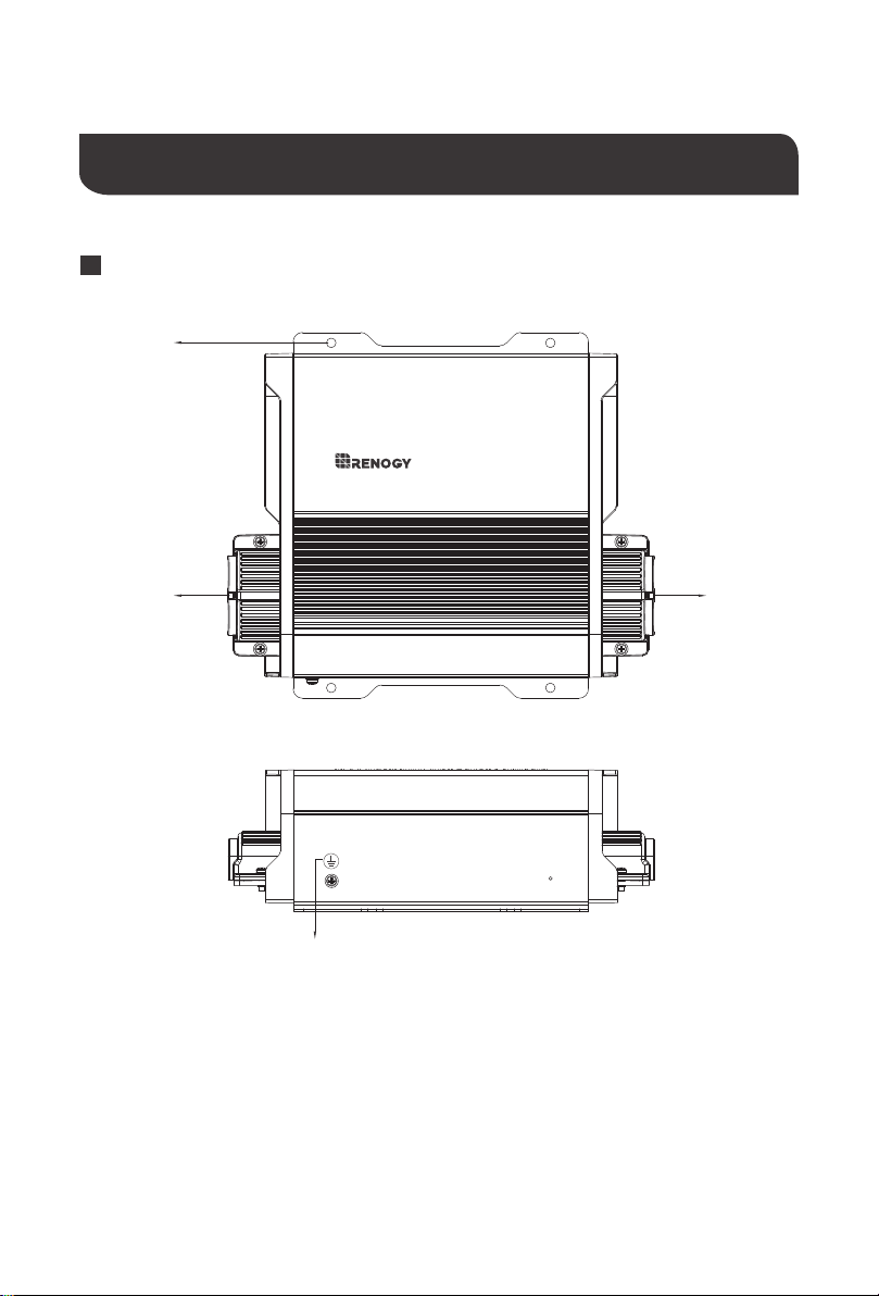
Identification of Parts
Product Overview
Top/ Front View
1.Grounding Lug
2.Output Port: 36V or 48V Battery Connections
3.Mounting Holes (4)
4.Input Port: Solar Panel input connections, 15~40V (VOC)
10a solar charge controller
rover boost
1
2
3
4
05
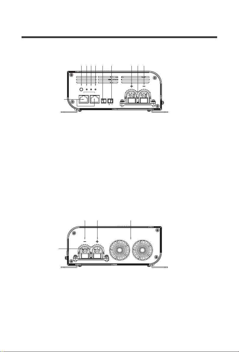
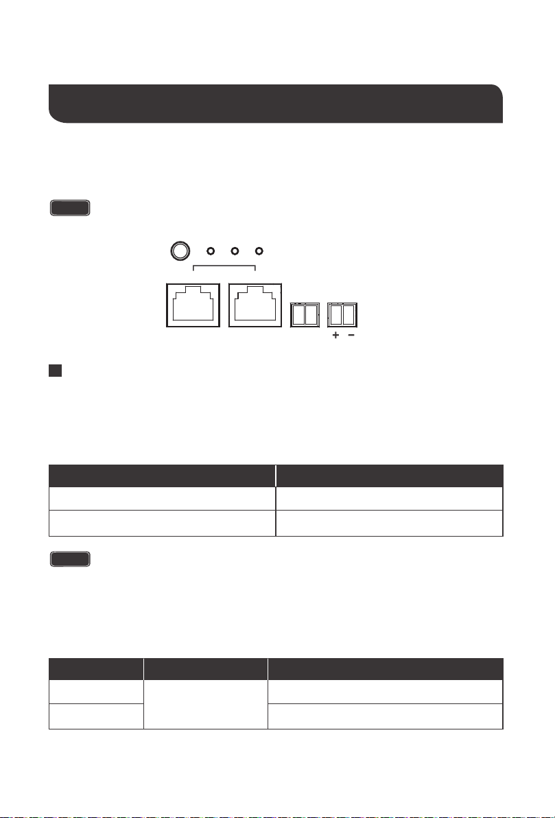
Left View
5.RS485 / CAN Communication Ports
6.Setting Button
(Battery Type,CAN Host Mode)
7.Battery Type LED Indicator
8.Battery Status LED Indicator
9.PV Status LED Indicator
10.36/48V Positive Battery Output Terminal
11.36/48V Negative Battery Output Terminal
12.Removable Battery Output Cable Housing
13.Battery Voltage Sensor Port
(Polarity Sensitive, Optional)
14.Battery Temperature Sensor Port (Optional)
15. Removable PV Input Cable Housing
16. Negative PV Input Terminal
17. Positive PV Input Terminal
18. Cooling Fans
Right View
input
SET
TYPE
rs485 can
BATT
temp batt
PV
output
76
5
8 9 14 13 10
16 17
15
18
12 11
06
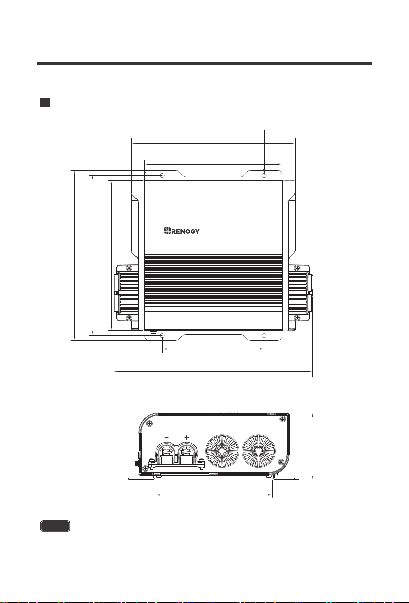
NOTE
The dimensions have a ±0.5mm tolerance.
Dimensions
10a solar charge controller
rover boost
input
[155.0mm]
6.1in
[115.0mm]
4.5in
[133.3mm]
5.3in
[223.9mm]
8.8in
[170.0mm]
6.7in
[74.5mm]
2.9in
[180.9mm]
7.1in
[191.9mm]
7.6in
[185.0mm]
7.3in
[5.0mm]
4xφ0.2in
07
NOTE
Do not use this sensor with Lithium batteries.
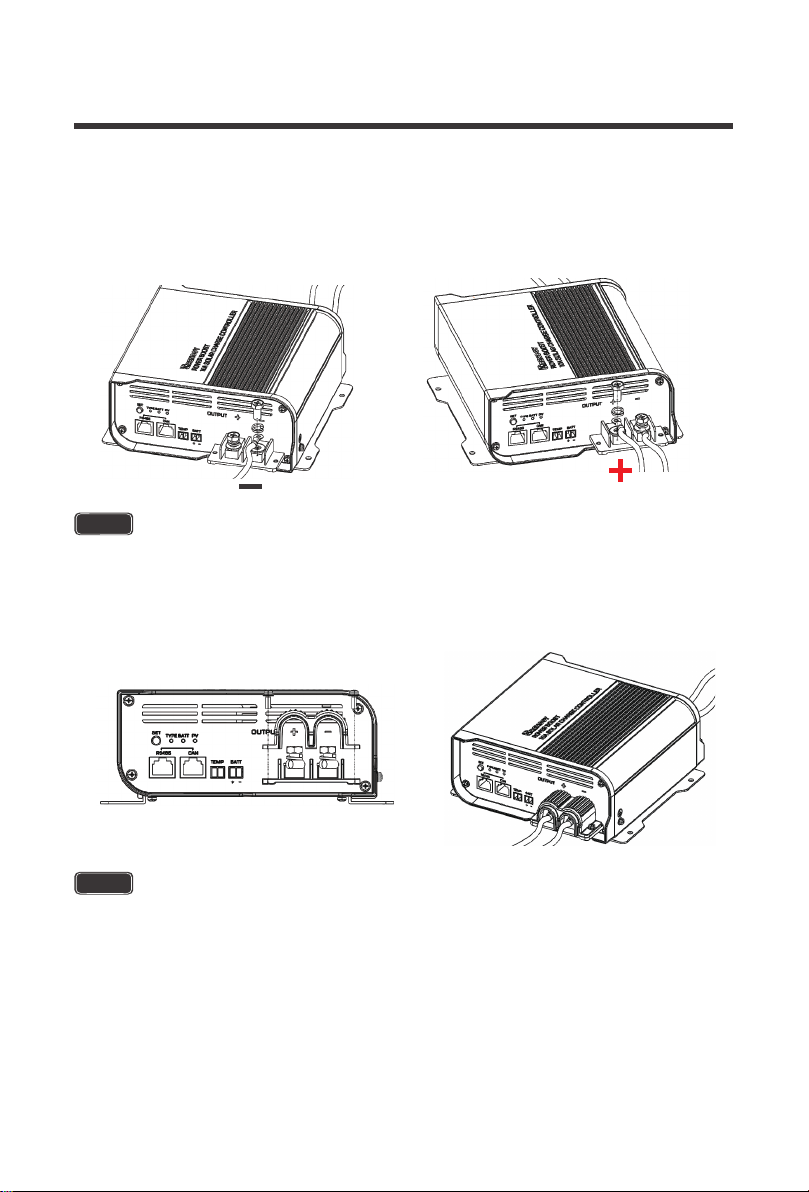
The Rover boost terminals are secured not only by tightening the cable entry hatch, but also
by utilizing the removable cable housing to secure the incoming and outgoing connections.
Mounting Screws for the Input/output Terminals
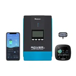
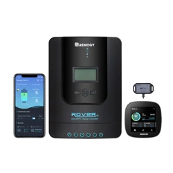
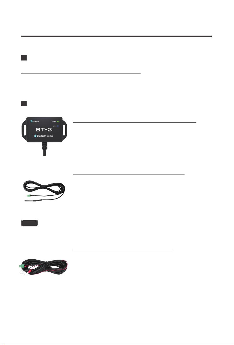
The RCM-BT2 is a great addition to any Renogy charge controller
with an RS485 port. Pair the controller to the Renogy DC Home App
to monitor your system using a smart device like a cell phone or
tablet. Set custom charging parameters using User Mode and
monitor your system in real time.
Renogy BT-2 Bluetooth Module (Model: RCM-BT2)
The RTSCC measures the temperature at the battery bank and uses
this data for very accurate temperature compensation. The sensor is
supplied with a 9.8 ft cable length that connects to the charge
controller. Simply connect the cable to the appropriate slot using the
green connector and place the sensor on top or on the side of the
battery bank and it will immediately start working.
Remote Temperature Sensor (Model: RTSCC)
The RVSCC provides users with more accurate battery charging
giving you peace of mind that the charge controller is operating as
effectively as it should. On certain applications with long line runs,
there can be a difference between the voltage measured at an MPPT
solar charger’s terminals and that measured at the battery terminals.
The RVSCC is the perfect solution by providing a more accurate
battery voltage to the controller and allowing it to adjust the charging
stage more precisely resulting in overall extension of your battery
life.
Renogy Voltage Sensor (Model: RVSCC)
Included Components
Optional Components
6 in / 154mm
6 in / 154mm
Installation
Connect the battery terminal wires to the Charge controller FIRST then connect the
solar panels to the charge controller SECOND. Connecting panels before the
battery may result in irreversible damage.
Never install the controller in a sealed enclosure with flooded batteries as gas may
accumulate and there is a risk of explosion.
Do not over-tighten the terminals. This could potentially break mounting
components rendering the controller useless.
Connections should be made according to Article 690 of the National Electrical
Code (NFPA 70) or the standards in force at the installation location.
CAUTION
CAUTION
WARNING
08
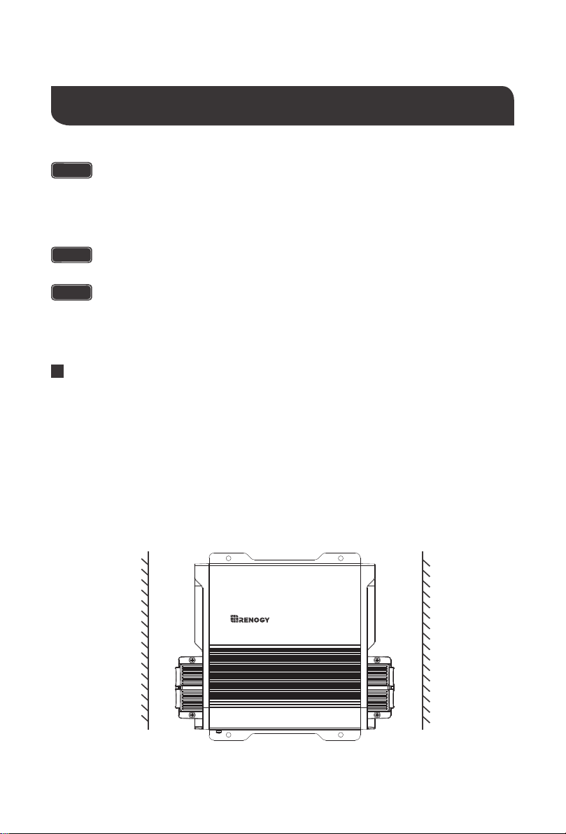
Mounting Recommendations
10a solar charge controller
rover boost
1. Choose Mounting Location—place the controller on a vertical surface protected from
direct sunlight, high temperatures, and water. Make sure there is good ventilation.
2. Check for Clearance—verify that there is sufficient room to run wires, as well as clearance
above and below the controller for ventilation. The clearance should be at least 6 inches (154mm).
3. Mark Holes
4. Drill Holes
5. Secure the charge controller.
09
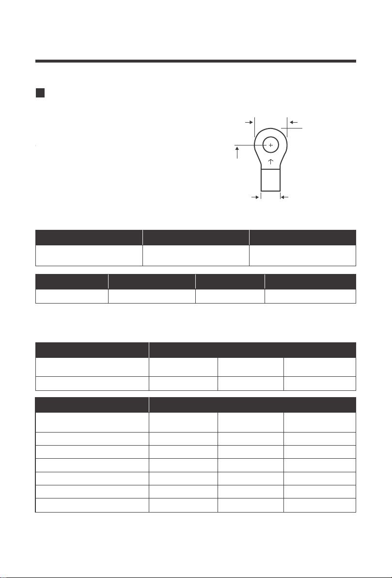
The Rover Boost accepts ring terminals or lugs.
Due to the terminal housing, ring terminals must
comply with the following instructions
The following recommendation is based off 3% maximum voltage loss. The recommended
wire sizing may not cover all unit applications that may exist.
Recommended Gauge and Ring Terminal Sizes
Ring Width
< 19mm
< 3/4”
< 14.5mm
< 9/16"
6mm
1/4"
Cable Width Ring Size Recommended
Specification
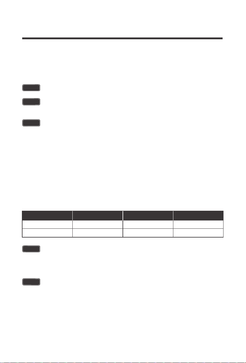
Battery Wiring 12 AWG 10A 15A-20A
Rated AmpsRecommended AWG Recommended Fusing
Specification
Battery Output Charging Amps
0 ~ 10 ft /
0 ~ 3m
11 ~ 20 ft /
3 ~ 6m
21 ~ 30 ft /
6 ~ 9m
12 ~ 10 AWG14 AWG 10 AWG10A
Recommended AWG
Specification
PV Input Charging Amps
0 ~ 10 ft /
0 ~ 3m
11 ~ 20 ft /
3 ~ 6m
21 ~ 30 ft /
6 ~ 9m
16 ~ 14AWG16AWG 14 ~ 12AWG100W ~ 5A
14 ~ 12AWG16 ~ 14AWG 10AWG200W ~ 10A
12 ~ 10 AWG14 ~ 12AWG 10 ~ 8AWG300W ~ 15A
10 ~ 8AWG14 ~ 12AWG 6AWG400W ~ 20A
8 ~ 6AWG12 ~ 10 AWG 6AWG500W ~ 25A*
8 ~ 6AWG10AWG 6 ~ 4AWG600W ~ 30A*
Recommended AWG
Cable Width
Ring Size
Ring Width

10
The Rover Boost is only suitable for 36V or 48V battery banks only. Not abiding by
these battery voltages may lead to irreversible damage to your controller or system
The positive or negative battery cable should be protected by a fast-acting fuse or
circuit breaker of 15A-20A, rated for the maximum battery voltage and connected
close to the battery terminal or power distribution block. This fuse will protect the
wiring in the event of a short circuit or controller damage.
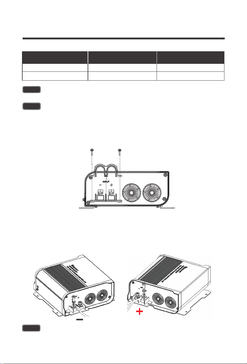
Locate the OUTPUT side. Expose the positive and negative battery output terminals by
unscrewing the M3 screws holding down the removable battery output cable housing.
A small spark while connecting the battery to the controller is ok. However, make
sure to have appropriate wiring at the input and output.
The M3 screws have a recommended torque of 0.5~0.8 Nm / 0.4~0.6 lb. ft. The
M6 screws have a recommended toque 4.1~5.0Nm / 3~3.7 lb. ft.
Be careful with the positive and negative poles of battery bank; reversing them or
having them make contact may cause irreversible damage not covered by warranty.
WARNING
The Rover Boost has reverse polarity protection for battery connections and extra
precautions must be taken when connecting Lithium Batteries. Do not have a PV
Source connected until the correct battery setting has been selected.
WARNING
NOTE
NOTE
The Rated Max PV Input Power is 500W (36V) or 650W (48V)
NOTE
Larger wire sizes will improve boost performance whereas smaller wire sizes will
reduce boost performance. When considering wiring, fuse, and connection options
think big and short as larger heavier components and shorter wire lengths offer less
resistance and voltage drop.
Battery Wiring
Wiring
WARNING - EXPLOSION HAZARD
Working in the vicinity of lead-acid batteries is dangerous. Batteries produce explosive
gasses during normal battery operation.
1.
11
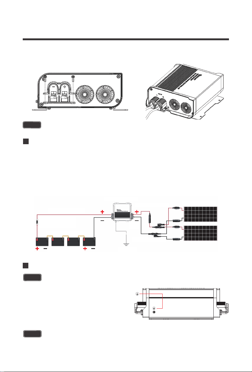
When finished, place the removable battery output cable housing back over your
connections. Make sure to not over-tighten the M3 screws.
3.
To ensure maximum safety, it is important to use correct wiring for either 36V or 48V battery
banks. Series connections are when batteries of the same size and type are combined, and
their voltages add up. The batteries Amp-Hour (Ah) Rating, however, remains the same.
Examples are below:
NOTE
The M6 screws have a recommended toque 4.1~5.0 N-m / 3~3.7 lb. ft.
NOTE
The M3 screws have a recommended torque of 0.5~0.8 N-m / 0.4~0.6 lb. ft.
Unscrew the negative M6 terminal stud, then place the negative Battery ring terminal onto
the negative port and screw the M6 terminal stud and washers together. Repeat the same
for the positive M6 terminal stud and positive Battery ring terminal.
2.
12
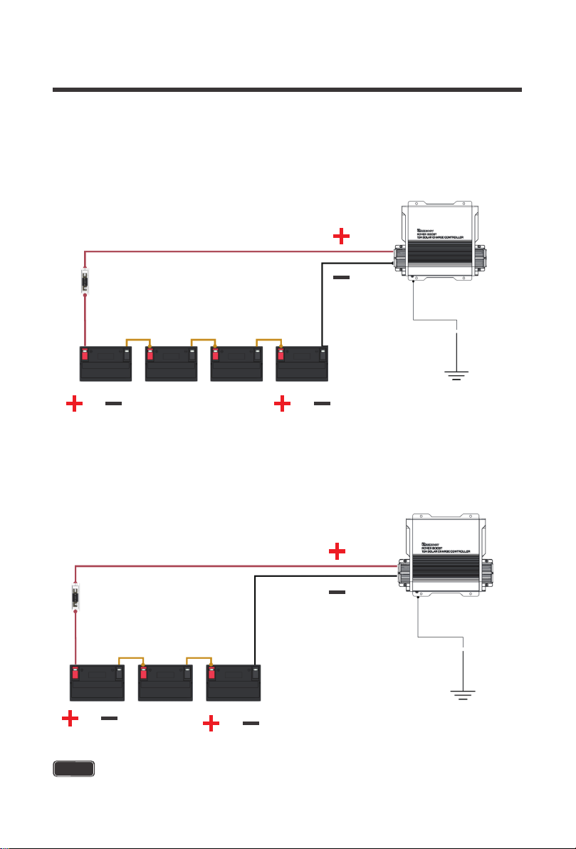
48V 100Ah Wiring
NOTE
The M3 screws have a recommended torque of 0.5~0.8 N-m / 0.4~0.6 lb. ft.
The M6 screws have a recommended toque 4.1~5.0 N-m / 3~3.7 lb. ft.
36V 100Ah Wiring
Assuming each battery is 12V 100Ah battery bank, you will combine 3 x 12V batteries in series
to achieve a 36V 100Ah battery bank. In series connections, the 12V voltages add up to 36V,
while the 100Ah Rating remains the same.
Assuming each battery is 12V 100Ah battery bank, you will combine 4 x 12V batteries in series
to achieve a 48V 100Ah battery bank. In series connections, the 12V voltages add up to 48V,
while the 100Ah Rating remains the same.
10A Rover Boost
12-10AWG Tray Cable
15A-20A
ANL Fuse Set+Cable
48V Battery System
Battery Interconnects
Ground
10A Rover Boost
12-10AWG Tray Cable
15A-20A
ANL Fuse Set+Cable
36V Battery System
Battery Interconnects
Ground
13
NOTE
WARNING
The Rover Boost is designed to automatically utilize MPPT technology to boost wasted power
into usable charge current.
The following represents typical modules and their properties. Depending on how many solar
panels you are combining, appropriate series or parallel connections will be needed to achieve
the maximum power of the charge controller. Series connections will connect positive to
negative and add up the voltage, while the current remains the same. The controller will utilize
excess voltage and convert it into useable current. Parallel connections will connect positive to
positive on one side and negative to negative on the other side resulting in the voltage
remaining the same while the current adds up, thus increasing you net input current power.
The following chart represents the operating Voc range for panels respective to the battery
bank voltage. This information is found in the technical specifications for panels or in the solar
panel sticker. The Rover Boost features a power limiting clipping function, where the power is
limited within a specified range, and therefore allows the battery to charge at correct
parameters despite the oversized input power.
Ring terminals are recommended for the input and output connections of the Rover
Boost.
NOTE
This chart represents typical values found with the respective cells on the solar
modules. Actual values might differ depending on the manufacturer.
Failure to abide by the chart may result in damage to your system or system
components. Please pay close attention to your solar panel specifications when
connecting them to the controller.
WARNING
Not compatible with 72 cell PV Modules.
WARNING
The Rover Boost may be permanently damaged if exceeding the Max PV Power
w/ Power Limiting.
Solar Panel Wiring
Typical Modules
PV Requirements
Solar Module
32.7V
19.5V
39.8V 300W-350W
23.9V
300W
50W-200W
60 cells
36 cells
Solar Vmp Solar Voc
Rated Power
14
NOTE
The M6 screws have a recommended toque 4.1~5.0 N-m / 3~3.7 lb. ft.
NOTE
If the VOC is greater than 45V, charging disconnects; When the VOC is less than
40V, then it resumes charging.
Exceeding the Rated Max Power will put the controller in Power Limiting Protection
Mode up to 600W/36V or 800W/48V. Afterwards the unit will shut down.
Locate the INPUT side. Expose the positive and negative PV input terminals by unscrewing
the M3 screws holding down the removable PV input cable housing.
1.
Unscrew the negative M6 terminal stud, then place the negative PV ring terminal onto the
negative port and screw the M6 terminal stud and washers together. Repeat the same for
the positive M6 terminal stud and positive PV ring terminal.
2.
System Voltage
15 ~ 40 VDC
15 ~ 25 VDC
650W
500W
48 V
36 V
Range Rated Max PV Power
CAUTION
15
Typical Setup
200W System, 48V System
A typical setup is demonstrated utilizing 2 x 100W panels in parallel where all the positive
connectors connect, and all the negative connections connect before they are connected at
the input of the Rover Boost. Other items include: a set of MC4 branch connectors, an inline
MC4 fuse, an Adapter kit, the 10A Rover Boost, a set of tray cables, an ANL Fuse set and
cable, battery interconnects, and a 48V battery bank system.
NOTE
The M3 screws have a recommended torque of 0.5~0.8 N-m / 0.4~0.6 lbf. ft.
NOTE
The M3 screws have a recommended torque of 0.5~0.8 N-m / 0.4~0.6 lbf. ft.
When finished, place the removable PV input cable housing back over your connections.
Make sure to not over-tighten the M3 screws.
3.
CAUTION
Grounding
Do NOT ground PV input and Battery output individually, use the controller ground lug.
Grounding is not necessary for the operation and
is at user’s discretion. If grounding, do not ground
the PV input and Battery output connections
together. Instead, Locate the M3 ground screw
on the front of the Rover Boost. Unscrew the
terminal, place a M3 ring connector and ground
the system to earth ground.
10A Rover Boost
Solar Panels(Parallet)
10-12A MC4 Fuse
12-10AWG Tray Cable
15A
ANL Fuse Set+Cable
48V Battery System
Battery Interconnects
Ground
MC4 Branch
Connectors
12-10AWG
Adapter Kit
16
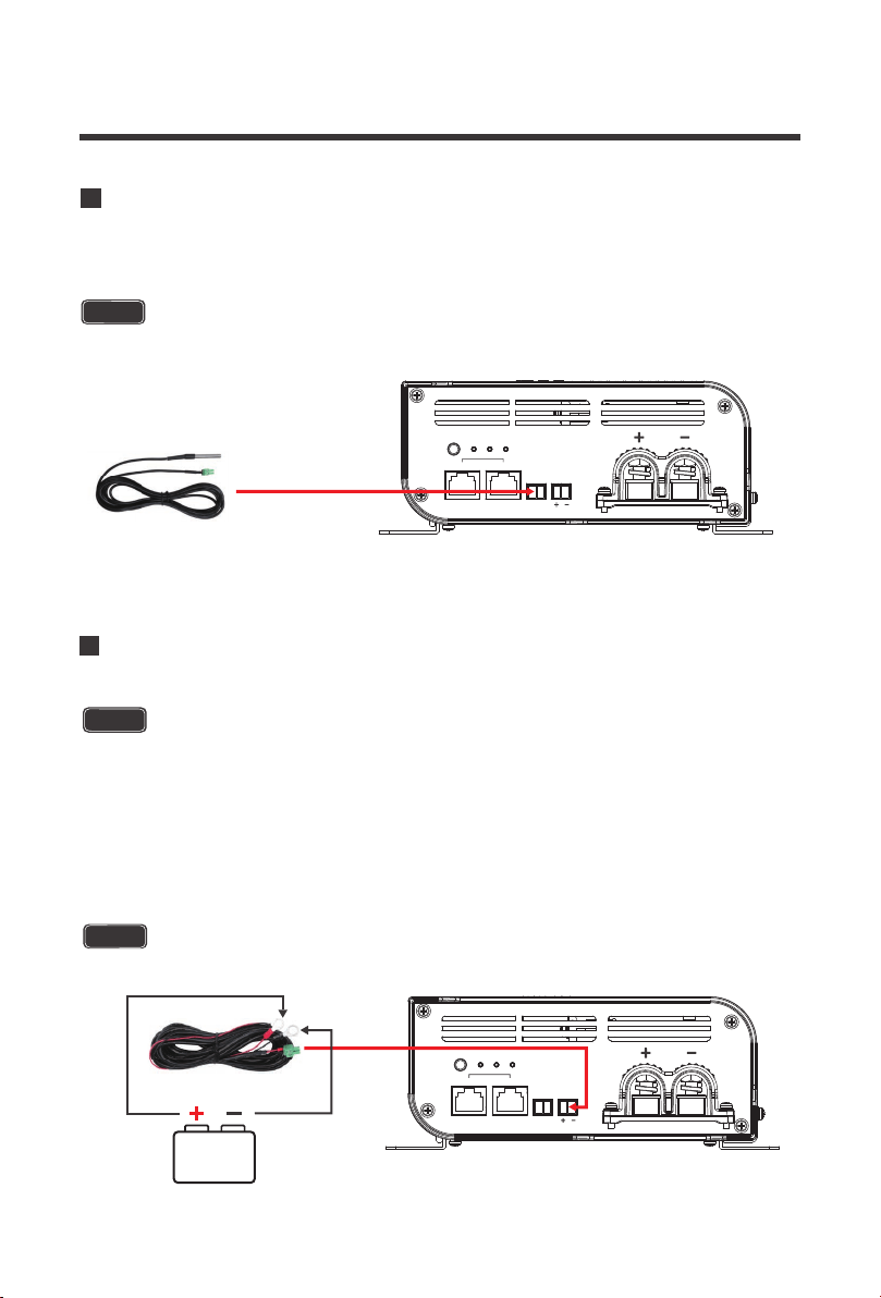
Connecting the Temperature Sensor (Model: RTSCC)
The RTSCC will include the 2-pin green housing connector. Simply connect the 2-pin
connector to the TEMP port on the OUTPUT side of the Rover Boost.
NOTE
Separate purchase required.
SET
TYPE
rs485 can
BATT
temp batt
PV
output
Connecting the Battery Voltage Sensor (Model: RVSCC)
The RVSCC is polarity sensitive and you must connect it to the correct positive (+,
left pin) and the correct negative (-, right pin) battery terminals as well as match the
polarity written on the BATT port on the Rover Boost (+, -).
The RVSCC will include the 2-pin green housing connector on one end as well as
positive and negative ring connectors on the other end. First connect the negative
and positive ring terminals to your battery bank. Make sure it is the correct polarity.
Next, simply connect the 2-pin connector to the BATT port on the OUTPUT side of
the Rover Boost.
NOTE
Separate purchase required.
SET
TYPE
rs485 can
BATT
temp batt
PV
output
CAUTION
17
Set the correct battery type before the first time use
CAUTION
Operation
The Rover Boost is relatively simple to operate. You will need to set your battery type using the
SET button and then the controller can take care of the rest. The LED Indicators and SET
button are found on the OUTPUT side of the Rover Boost.
The Rover Boost requires that the battery bank be 36V or 48V to operate. It features automatic
battery recognition for deep cycle lead acid and VRLA batteries. It is always good practice to
double check the recognized battery matches the intended voltage of the battery bank. Lithium
batteries will need to be set manually when charging 36V / 48V systems. Auto Recognition will
behave in the fashion indicated below:
A fully charged 36V non-lithium battery that is connected for the first time may have a voltage
that exceeds the 42V threshold. This may include situations where the controller is restarted
or disconnected and then reconnected. Therefore, the Rover Boost will flash the TYPE LED to
toggle the system voltage in the fashion indicated below:
Auto Recognition and Toggle
SET
TYPE
rs485 can
BATT
temp batt
PV
NOTE
Auto Detection is intended for 36V / 48V non-lithium batteries.
Auto Detect System Voltage
36 V
48 V
< 42V
> 42V
Battery Voltage Range
System Voltage Battery Voltage Range
36 V
> 42V
48 V
Long press (5s) the SET button to toggle 36V
Short press the SET button to toggle 48V
Toggle
18
AGM (Green) is the default battery type for the Rover Boost. To change or set the battery type,
long press the SET button for approximately 8 seconds. The Type Indicator will flash a color
depending on the battery type indicated below. Tap the SET button to change between battery
types until the appropriate TYPE color is flashing. To set the battery type, long press the SET
button again and the battery type will be set. Alternatively, you may leave the battery type
flashing and after 15 seconds of inactivity, the battery type flashing will be set as the battery type.
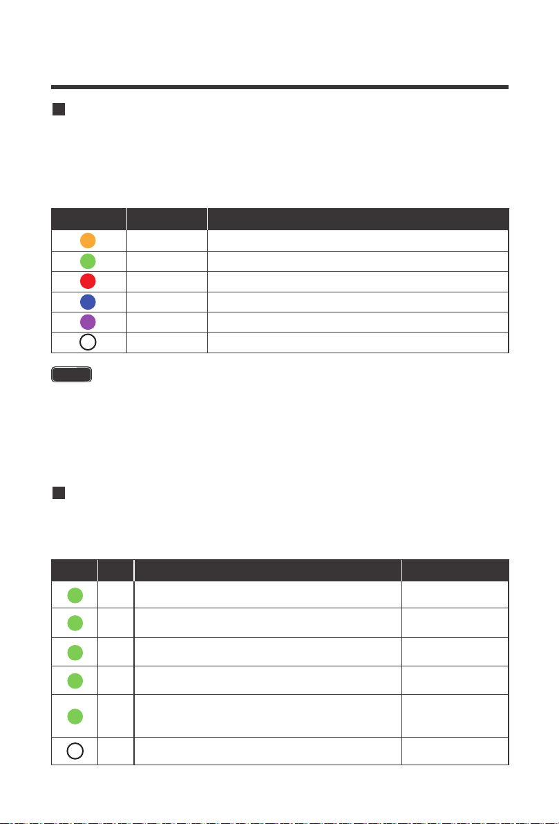
The Rover Boost LED indicators work to provide battery type information, battery status
information, and solar charging information.
Set the Battery Type
LED Indicators
NOTE
When a non-lithium battery is connected for the first time, and the battery voltage
is detected to be greater than 42V, the TYPE LED will flash, short press the button
to enter 48V, long press to enter 36V.
By Default, User mode will operate as a 48V Lithium-iron Phosphate (LFP) – 16
Strings battery charging profile. User mode can be customized via software app
development utilizing the BT-2 Bluetooth Module (RCM-BT2) and Renogy DC
Home App.
TYPE LED
Yellow Gel
AGMGreen
FloodedRed
36V Lithium-iron Phosphate (LFP) – 12 StringsBlue
48V Lithium-iron Phosphate (LFP) – 15 StringsPurple
User (48V Lithium-iron Phosphate (LFP) – 16 Strings)White
Color Battery Type
PV LED
Green
Always on
Color Behavior Charge State
PV LED Indicator
Bright, always on
MPPT
Bulk Charging
PV is not charging
or not detected
Green
Slow Flashing
ON 1 second, OFF 1 second, cycle is 2 seconds
Boost Stage
Green
Single Flash
ON 0.1 second, OFF 1.9 seconds, cycle is 2 seconds
Float Stage
Green
Quick Flashing
ON 0.1 second, OFF 0.1 second, cycle is 0.2 seconds
Equalization Charge
Green
---
Double Flashing
OFF
ON 0.1 seconds, OFF 0.1 second, ON 0.1 seconds
OFF 1.7 seconds
Lithium Activation
or Power Limiting
19
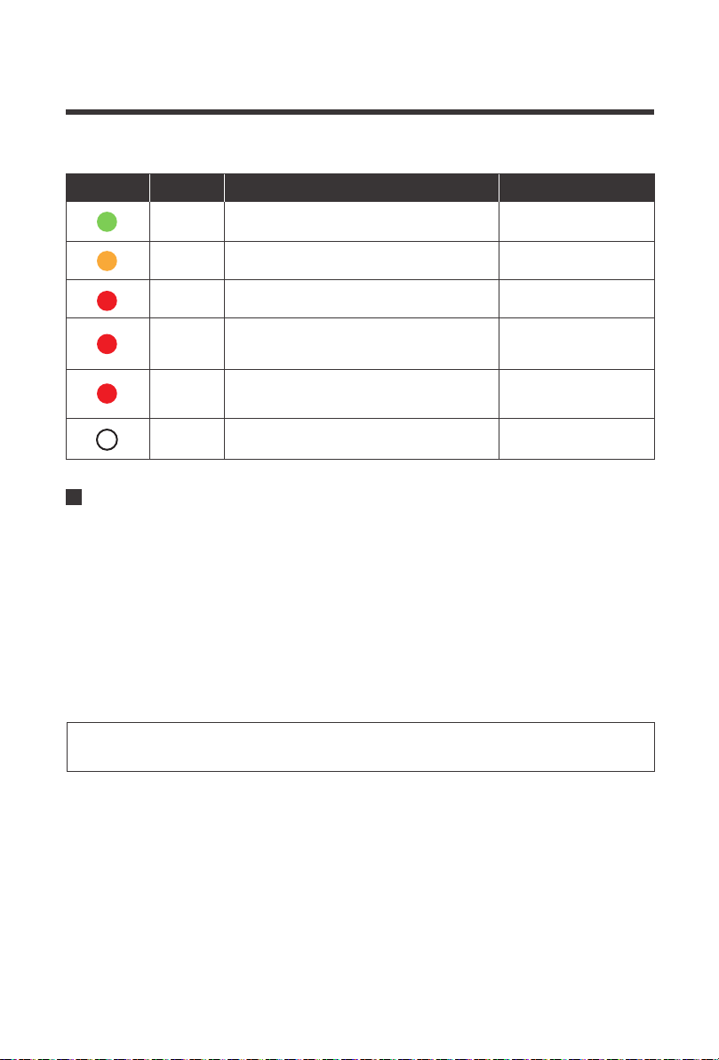
MPPT Technology
BATT LED
Green
Always on
Color Behavior Charge State
Battery LED Indicator
Bright, always on
Battery is
fully charged
Battery is not detected
Yellow
Always on
Always on
Bright, always on
Bright, always on
Battery voltage
is normal
Red
Battery undervoltage
warning
Red
Slow Flashing
ON 1 second, OFF 1 second,
cycle is 2 seconds
Battery over
discharged
disconnected
Red
---
Quick Flashing
OFF
ON 0.1 second, OFF 0.1 second,
cycle is 0.2 seconds
Battery Overvoltage or
Over temperature
PV Array voltage and temperature have a direct influence on the voltage boost performance.
A PV module at constant solar intensity will vary the power output depending on temperature
changes. Therefore, it is important to note that a cooler PV array can produce a higher voltage,
and therefore more power, than a hot PV array. When the PV voltage is enough for the MPPT
operating range then a constant power output is delivered to the battery.
Therefore, assuming 100% efficiency:
Power In = Power Out
Volts In * Amps In = Volts out * Amps out
The MPPT Charge Controller utilizes Maximum Power Point Tracking Technology to extract
maximum power from the solar module(s). The tracking algorithm is fully automatic and does
not require user adjustment. MPPT technology will track the array's maximum power point
voltage (Vmp) as it varies with weather conditions, ensuring that the maximum power is
harvested from the array throughout the course of the day.
The Rover Boost will “boost” up the voltage in the solar system. The power generated in the
solar panels is the same power that is transmitted into the battery bank. Power is the product
of Voltage (V) x Amperage (A).
Voltage Boost
20
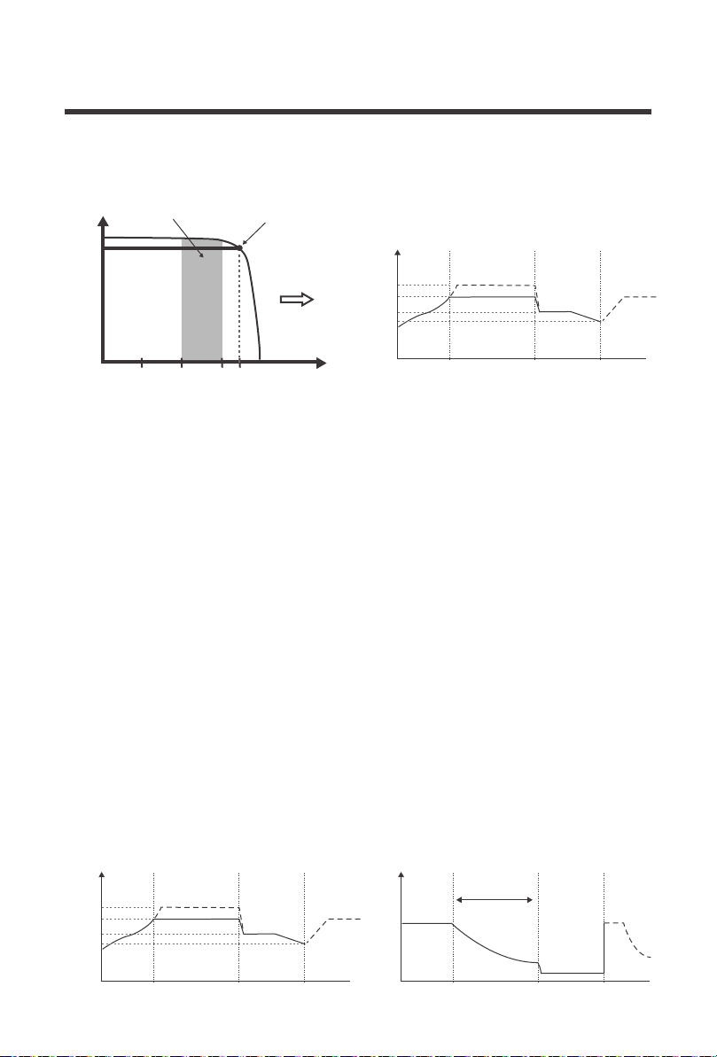
The MPPT charge controller has a 4-stage battery charging algorithm for a rapid, efficient, and
safe battery charging. They include: Bulk Charge, Boost Charge, Float Charge, and
Equalization.
Four Charging Stages
Temperature is a huge enemy of solar modules. As the environmental temperature
increases, the operating voltage (Vmp
) is reduced and limits the power generation of the solar
module. Despite the effectiveness of MPPT technology, the charging algorithm will
possibly
not have much to work with and therefore there is an inevitable decrease in
performance.
This is why it is preferred to have PV modules be in cooler ambient temperatures for the
greatest boost.
In the chart above, the maximum power point at which the PV module delivers maximum
power (17V*5.8A) is observed, and the Rover Boost increases the voltage to Charge an
AGM 48V battery bank. The Rover Boost will continually recalculate the maximum power
voltage as operating conditions change and extract this power. The input power feeds a
switching type power converter which increases the voltage to the battery.
This is why it is preferred to have PV modules be in cooler ambient temperatures for the
greatest voltage boost.
Limiting Effectiveness
Maximum
Power Point
Current vs. Voltage (12V System) Output Power (48V System)
Typical Battery
Voltage Range
CURRENT
VOLTAGE
100W Solar
58.4V
55.2V
Rover Boost
48V AGM
10 15
5.88A
17
Battery
Voltage
Equalize
Boost
Float
Recharge
Bulk Charge
A B C
Constant charging Float Charge
Boost
Time
Bulk
Battery
Current
Time
Max Current
Duration Time:2h
Battery
Voltage
Equalize
Boost
Float
Recharge
Bulk Charge
A B C
Constant charging Float Charge
Boost
Time
Bulk

21
Bulk Charge: This algorithm is used for day to day charging. It uses 100% of available solar
power to recharge the battery and is equivalent to constant current. In this stage the battery
voltage has not yet reached constant voltage (Equalize or Boost), the controller operates in
constant current mode, delivering its maximum current to the batteries (MPPT Charging) .
Float Charge: After the constant voltage stage, the controller will reduce the battery voltage
to a float voltage set point. Once the battery is fully charged, there will be no more chemical
reactions and all the charge current would turn into heat or gas. Because of this, The charge
controller will reduce the voltage charge to smaller quantity, while lightly charging the battery.
The purpose for this is to offset the power consumption while maintaining a full battery storage
capacity. In the event that a load drawn from the battery exceeds the charge current, the
controller will no longer be able to maintain the battery to a Float set point and the controller will
end the float charge stage and refer back to bulk charging.
Constant Charging: When the battery reaches the constant voltage set point, the controller
will start to operate in constant charging mode, where it is no longer MPPT charging. The current
will drop gradually. This has two stages, equalize and boost and they are not carried out constantly
in a full charge process to avoid too much gas precipitation or overheating of the battery.
Boost Charge:
Boost stage maintains a charge for 2 hours by default. User Mode
can adjust the constant time and preset value of boost per their demand.
Equalization: Is carried out every 30 days. It is intentional overcharging of the battery for
a controlled period of time. Certain types of batteries benefit from periodic equalizing charge,
which can stir the electrolyte, balance battery voltage and complete chemical reaction.
Equalizing charge increases the battery voltage, higher than the standard complement
voltage, which gasifies the battery electrolyte.
Equalization may increase battery voltage to a level damaging to sensitive DC loads.
Ensure that all load allowable input voltages are greater than the equalizing charging
set point voltage.
Once equalization is active in the battery charging, it will not exit this stage unless
there is adequate charging current from the solar panel. There should be NO load on
the batteries when in equalization charging stage.
WARNING
Over-charging and excessive gas precipitation may damage the battery plates and
activate material shedding on them. Too high of equalizing charge or for too long
may cause damage. Please carefully review the specific requirements of the battery
used in the system.
WARNING
WARNING
Communication Ports
22
The Rover Boost has a reactivation feature to awaken a sleeping lithium battery. The protection
circuit of lithium battery will typically turn the battery off and make it unusable if over-discharged.
This can happen when storing a lithium battery pack in a discharged state for any length of time
as self-discharge would gradually deplete the remaining charge. Without the wake-up feature to
reactivate and recharge batteries, these batteries would become unserviceable and the packs
would be discarded. The Rover Boost will apply a small charge current to activate the protection
circuit and if a correct cell voltage can be reached, it starts a normal charge.
Lithium Battery Activation
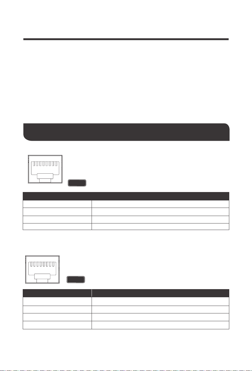
RS485 Port: The RS485 Port on the Rover Boost is dedicated to
monitoring the controller through the BT-2 Bluetooth Module with extra
features seen on the Renogy DC Home App. This will utilize an RJ45
Communication Cable.
Pin No.
1
2
3
4
+5V
RS485-A
RS485-B
GND
Parameter
NOTE
The accessory requires additional purchase
RS485
1 2 3 4 5 6 7 8
CAN bus: The controller area network port on the Rover Boost is dedicated
to paralleling Rover Boost controllers utilizing the communication function
for lithium batteries.
NOTE
The accessory requires additional purchase
1 2 3 4 5 6 7 8
*RS485 initial baud rate is 9600bps
Pin No.
5
6
7
8
NC
CAN_H (CAN bus signal)
NC
CAN_L (CAN bus signal)
Parameter
*CAN initial baud rate is 500Kbps

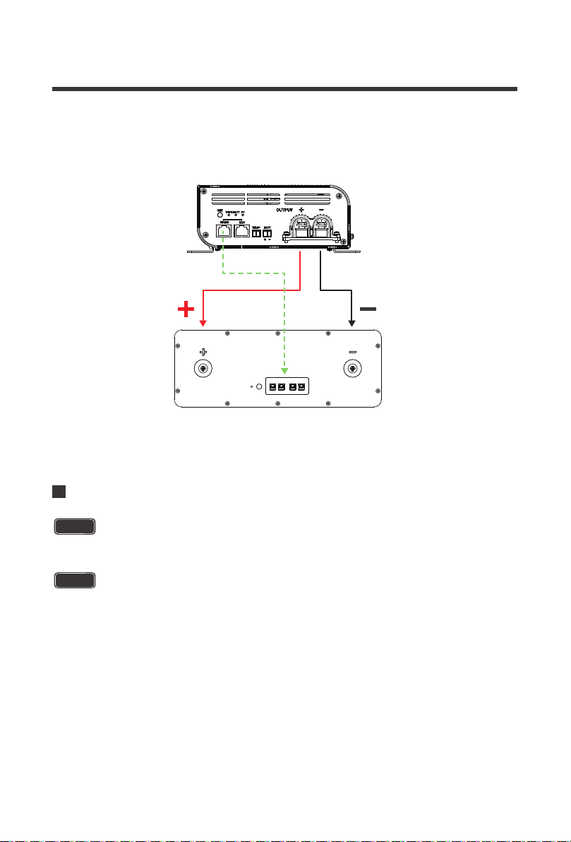
For Renogy Smart Lithium batteries with BMS, the Rover Boost’s RS485/CAN communication
ports will be used to synchronize smart battery information and allow up to 2 x Rover Boosts to
communicate with each other as separate but paralleled systems to the same battery bank.
One controller in the system will be the Host, or the main controller, while the other controller
will synchronize its logic to the Host controller. The Host controller will receive and assign
battery charging information to the non-host controller, synchronizing charging logic for the
connected controllers. The RS485/CAN communication functions have the following major
advantages for Smart lithium Battery setups:
Typical chargers have a preset logic when charging batteries. The logic is based off voltage
setpoints and time limits. The advantage for the Lithium communication is that the controller will
communicate with the BMS directly and adjusting charging for a more accurate and precise
algorithm. Charging logic, assuming power supply source, may also charge longer than typical
chargers for the most precise charging algorithm.
23
Host Mode Communication
Host Mode on 48V Smart LFP Battery
Improved and accurate Battery Charging
Direct communication with the BMS gives the controller access to state of charge information
and aids in BMS cell balancing for 100% charging. CAN logic reads battery BMS and
communicates exact SOC% and voltage values which will keep sending charge until fully
charged to 100%
The added communication between controller and battery automatically adjusts to the settings
rated by the BMS directly.
Direct BMS Communication
Accurate communication takes care of voltage compensation so that no battery voltage sensor
is needed, as the most accurate charging algorithm is in place.
1.Connect the Rover Boost to the positive and negative battery terminals
2.Set the battery type on the controller. In this case we will select 48V LFP, or purple.
3.Connect an ethernet cable between the Rover Boost’s RS485 or CAN communication port
and the Smart LFP Battery’s CAN communication port.
Make sure the polarity is correct. Reverse polarity on a Lithium battery w/ BMS may
cause irreversible damage to the charge controller and not covered by warranty.
Use ethernet cables that are CAT5 or higher. Follow the steps below to set up the
Rover Boost with the Renogy 48V Smart LFP Battery
Do not connect any solar panels to the Rover Boost when first setting up the battery.
No Battery Voltage Sensor Needed
NOTE
CAUTION
24
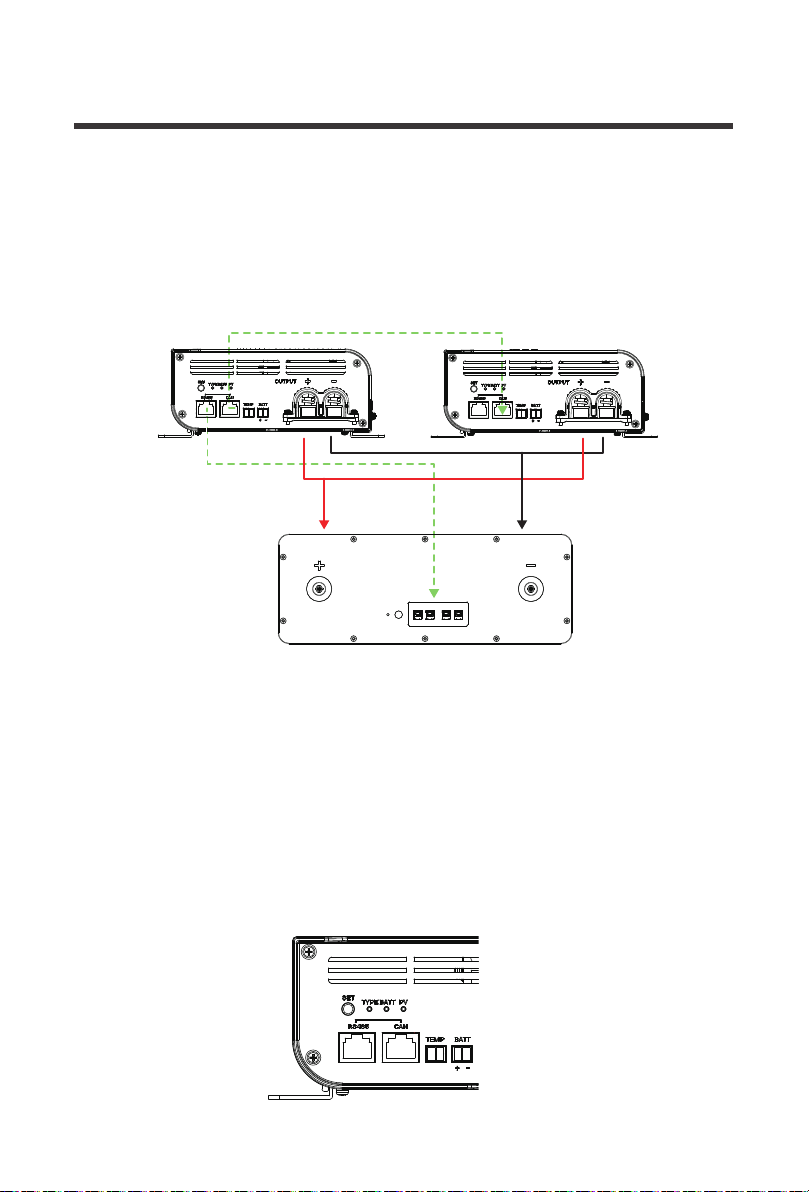
Paralleling 2 Rover Boosts w/ a 48V Smart LFP Battery
4.Press and hold the SET button for 20 seconds on the Rover Boost. This will activate the CAN
host function and the battery type light will flash once every 5 seconds. Now the controller is
communicating and synchronizing the battery recognition information.
1.To get started, both controllers need to be connected to the same battery bank. Correctly
connect the positive and negative terminals from the Rover Boost 1 and Rover Boost 2 to the
appropriate positive and negative terminals on the smart 48V LFP Battery. Then, connect an
ethernet cable from the CAN port on Rover Boost 1 to the CAN port on Rover Boost 2. Lastly,
select your Host Controller. We will assume Rover Boost 1.
Make sure the polarity is correct. Reverse polarity on a Lithium battery w/ BMS may
cause irreversible damage to the charge controller and not covered by warranty.
Up to 2 Rover Boosts can be connected in parallel and will charge at the same time maximizing
energy in the Bulk/MPPT Stage. Once the Rover Boost enters Boost Stage, then the Host
Function will automatically disable the non-Host Boost Controller as only 1 controller can be
boosting on the Lithium battery bank. In the event Host function is accidentally pressed, long
press again for 20 seconds to clear out of the host mode and exit.
Do not connect any solar panels to the Rover Boost when first setting up the battery.
NOTE
CAUTION
(Model: RBT50LFP48S)
Smart 48V LFP Battery
Rover Boost 1
Ethernet(Cat5 and above)RS485 to CAN
Use ethernet cables that are CAT5 or higher
RS485 RS485 CAN CAN
25
(Model: RBT50LFP48S)
Smart 48V LFP Battery
Rover Boost 1 Rover Boost 2
Ethernet(Cat5 and above)RS485 to CAN
4.Press and hold the SET button for 20 seconds on Rover Boost 1. This will activate the CAN
host function and the battery type light will flash once every 5 seconds. Only one Rover Boost
at a time can be set as the host in a single system and during this time the controllers are
communicating and synchronizing the battery recognition information.
5.Both Rover Boost controllers should have the same TYPE LED. The synchronization is
complete and both controllers are now synced to the 48V Smart LFP Battery
2.Set the battery type on the host controller, Rover Boost 1. In this case we will select 48V LFP,
or purple.
3.Next, run an ethernet cable between the Host controller’s (Rover Boost 1) RS485
communication port to the CAN communication port on the 48V Smart LFP Battery.
RS485 RS485 CAN CAN
26
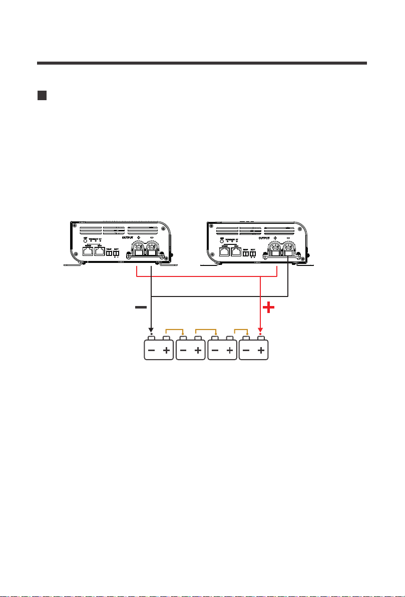
48V Battery Bank
Rover Boost 1 Rover Boost 2
In Non-lithium batteries, the batteries do not have a BMS and will not be able to communicate
synchronization information. Therefore, it is recommended to keep the controller’s distance and
wiring the same so the controllers can both detect the same battery bank and connect in
parallel. Therefore, the CAN Host function will not be in effect for Non-Lithium batteries.
1.To get started, simply connect both Rover Boost controllers to the same battery bank.
Paralleling 2 Rover Boosts w/ Non-Lithium

BATT LED Behavior Protection Cause / Fix
The controller is detecting a low battery voltage and
alerting the user
1.Use a multi-meter to check the battery reading
and verify whether the LED matches your intended
battery type and voltage. If the battery is low,
disconnect any loads and let the battery charge for
an extended period.
The Rover Boost is equipped with electronic protections to protect the controller and the
system. If the Rover Boost is not functioning correctly, it may be undergoing an internal
electronic protection. This is not indicative of a defective controller but may require some
troubleshooting to resume normal operation mode.
The Rover Boost has the following protections: battery undervoltage warning, battery
overvoltage, battery over-temperature, battery under-temperature, battery reverse polarity,
battery open circuit, PV reverse polarity, PV overvoltage, PV short circuit, PV Power Limiting,
back-flow protection, and controller internal over-temperature.
27
Electronic Protections and Troubleshooting
BATT LED
Red
Bright,
always on
Battery
undervolta
ge
warning
Always on
The battery has discharged below the under-voltage
warning and needs to be recharged. The controller has
stopped charging utilizing the electronic protection and
may have disconnected from the system.
1.Use a multi-meter to read the battery charging
voltage and verify the voltage is within the battery
charging parameters seen in Technical Specifications –
Battery Charging for your respective type.
2.Disconnect any loads from the battery and ensure
your panels are working and let the Rover Boost
charge the battery.
Red
ON 1
second,
OFF 1
second,
cycle is 2
seconds
Battery over
discharged;
disconnected
Slow
Flashing
The battery is connected to the controller but not
charging or not detected. This is a protection for
non-lithium batteries. Extra caution must be taken
with Lithium batteries in reverse polarity. This may
cause irreversible damage to the unit as a reversely
connected battery may be interpreted as a
discharged battery and undergo Lithium Activation.
1.Use a multi-meter to verify a battery voltage as well as
the battery voltage being within a 36V / 48V system by
comparing your values against the Technical
Specifications –Battery Charging, for your respective type.
_
Battery
Reverse
Polarity
OFF

28
ON 0.1
second,
OFF 0.1
second,
cycle is
0.2
seconds
2.Use a multi-meter to verify the correct positive and
negative polarity matches the polarity seen on the
OUTPUT port.
Use extra caution when connecting to Lithium
batteries. Reverse polarity protection is valid
unless there’s PV input source connected.
_
Battery
Overvoltage
Quick
Flashing
ON 0.1
second,
OFF 0.1
second,
cycle is
0.2
seconds
Quick
Flashing
_ _
Battery
Open
Circuit
The battery is charging at a higher rate than the
system voltage. The controller has stopped
charging utilizing the electronic protection.
1.Use a multi-meter to read the battery charging
voltage and verify the voltage is within the battery
charging parameters seen in Technical Specifications
– Battery Charging for your respective type.
2.Verify the correct battery voltage for Non-lithium
batteries or verify the correct TYPE LED for LFP batteries.
3.Toggle the controller by disconnecting and
reconnecting the battery to verify the proper system
voltage (36V/48V).
4.Check your solar panel input. Use a multi-meter to
check that the incoming voltage is within 15 ~ 40V.
If this is a 36V system, the PV voltage should not
exceed 15 ~ 25VDC
The battery has unexpectedly disconnected from the
controller with active PV power running, no damage to
the controller despite PV running with no battery bank.
_
Battery
Over-temp
erature
The battery is in an environment where it is
over-heating via utilizing the default 77° F /25°C or
directly observed if using a temperature sensor. In
addition, this could indicate the battery s outside the
normal operating range of -31°F/ -35℃ ~ 149°F /+ 65℃
1.If Battery temperature is above the -31°F/ -35℃ ~
149°F /+ 65℃ range, the controller will stop
charging and only resume charging when the
temperature is within the range again.
2.Place the controller in a ventilated area or add
ventilation to your setup to rapidly cool the
controller.
1.Use a multi-meter to verify proper connections to the
OUTPUT battery terminal. Upon successful connection,
the controller will resume normal charging.
2.If you are using a fuse, double check the fuse to
make sure it has not been compromised.
CAUTION

29
PV LED
PV Behavior Protection Cause / Fix
The panels are connected to the controller but not
charging or not detected.
1.Use a multi-meter to verify a PV voltage as well as
the voltage being within 15 – 40VDC
2.Use a multi-meter to verify the correct positive and
negative polarity matches the polarity seen on the
OUTPUT port.
_
PV
Reverse
Polarity
OFF
In non-lithium setups or setups where the Lithium
battery is fine, the Rover Boost’s rated PV watts have
been exceeded and it is therefore current limiting.
1.Double Flashing will continue until the Controller
has exited MPPT/Bulk stage. Afterwards, it will
continue through the normal charge state LEDs.
There is no issue, and this is a protected function of
the Rover Boost if the PV watts stay within the
designated values:
Exceeding the Protection Mode Limits may
result in irreversible damage and not
covered by warranty.
_
PV Power
Limiting
_
PV
Overvoltage
OFF
The panels voltage is higher than the controller’s
maximum input.
1.Use a multi-meter to verify a PV voltage as well as
the voltage being within 15 – 40 VDC.
2.Check your solar panel input against your battery
system voltage. Use a multi-meter to check that the
incoming voltage is within 15 ~ 40VDC for 48V
systems. If this is a 36V system, the PV voltage
should not exceed 15 ~ 25VDC.
Green
Lithium
Activation
Double
Flashing
ON 0.1
seconds,
OFF 0.1
second,
ON 0.1
seconds,
OFF 1.7
seconds
Double
Flashing
ON 0.1
seconds,
OFF 0.1
second,
ON 0.1
seconds,
OFF 1.7
seconds
If you are using a Lithium battery, it may have
undergone over-discharged protection and the Rover
Boost is attempting to wake-up the battery. Refer to
Lithium Activation in the MPPT Technology Section
for more information.
1.Use a multi-meter to measure your battery voltage
and determine whether it has undergone a protection
mode. Disconnect any loads and let the Rover Boost
charge and wake the Lithium battery.
Power Limiting Watts
36V
Up to 600W
48V
Up to 800W
WARNING

30
More Troubleshooting Behaviors
Behavior Probable Cause Cause / Fix
The battery may be experiencing an electronic
protection, see disconnected, over-discharged,
reverse polarity, over/under temperature in BATT
chart above for individual fixes.
No battery Power
The system is
dead; no LEDs
PV Not detected
or incorrectly
connected
PV will not
display or
charge
The solar panels may be experiencing an electronic
protection, see reverse polarity, overvoltage in the
PV chart above.
High ambient
temperature
Rover Boost
was Charging
but then
stopped
Incorrect Battery
Type
Rover Boost
not charging
properly
1.Float mode
2.Shaded Panels
3.Low Insolation
4.High
temperature
5.Improper wiring
Charging
current is lower
than expected;
PV current may
also be low
1.The controller is normally operating an in Float
mode, where the current is reduced to control and
maintain the battery
2.Inspect the solar panels for any dust or debris on
the surface. Clear anything creating shade to
resume normal operation
3.Atmospheric conditions such as low clouds, haze, sun
setting will reduce the panel output as the insolation
conditions also drop attributing the lower power output.
Clearer conditions will increase performance
4.While not outside of operating conditions, higher
temperature reduce the efficiency of the solar panels
with excess heat, where the maximum power voltage is
not much higher than the battery voltage, leaving little
to Boost. Check the solar module against the typical
solar module chart to potentially switch the module.
5.The panels are experiencing higher voltage drop due
to undersized wiring, poor connections, or perhaps
higher environmental conditions. Double check and
secure all connections and verify correct gauges.
High temperature or residual temperature may
prevent the controller from resuming charge.
Ventilate the charge controller location or reduce PV
power to lower heat.
Non-lithium batteries have an automatic detection
feature based on the voltage of the battery to determine
36V or 48V charging. If you have a 48V Battery, make
sure to press the SET button to toggle the controller to
a 48V battery system, as it may be thinking it is a 36V
system. For 36V systems, do not toggle the SET button
and it will resume 36V system recognition.

31
Inspect the Rover Boost from time to time to ensure proper performance. For best controller performance:
1.Check the wiring going into the controller from the PV side and BATT side. Make sure there
is no wire damage or heavy exposure wear on the wiring
2.Tighten all terminals to ensure a secure connection and avoid added any resistance and heat build-up.
3.Inspect the Rover Bost for any external damage, environmental damage, or corrosion
4.Ensure PV array does not exceed the voltages designated for 36V and 48V battery charging.
5.Clean the controller as required with a cloth.
Maintenance

32
Technical Specifications
Model RCC10RVRB
Rated System Voltage
Rated Charge Current
Battery Operating Range
Battery Types
Power Limiting Protection
Max Input Current (short-circuit, Isc)
MPPT Tracking Efficiency
Idle Consumption
MPPT Charge Conversion
Efficiency
Temperature Compensation
Operating Temperature Range
Storage Temperature Range
Rated Max Charge Power
MPPT Voltage Range
Solar Input Voltage
Range (VOC)
Grounding Type
Enclosure Rating
Humidity
Electronic Protections
Terminal Range
Weight
Dimensions
Communication
Terminal Size
36V / 48V, Auto Recognition (Non-Lithium)
10A
30 ~ 65 VDC
AGM, GEL, FLOODED, LFP, USER
35A
Up to 600W/36V; 800W/48V
≥ 99%
≤ 2W
≥ 90%
-3mV / ℃ / 2V (Non-Lithium)
0mV / ℃ / 2V; no compensation (Lithium)
-31°F ~ 149°F / -35℃ ~ + 65℃
-40°F ~ 176°F / -40℃ ~ + 80℃
PV Input Power: 500W/36V; 650W/48V
Charging Power: 450W/36V; 600W/48V
15 ~ 25VDC @ 36V
15 ~ 40VDC @ 48V
15 ~ 25VDC @ 36V
15 ~ 40VDC @ 48V
Common Negative Lug (M3)
IP20
Battery overcharging, Battery over discharge,
Battery reverse polarity protection, PV reverse
polarity, PV Reverse flow, PV Short circuit, PV
Power Limiting,Controller internal over-temperature
protection, Charging over-current protection
0-95% RH
16 ~ 2 AWG
2.65 lbs / 1.2 Kg
RS485 / CAN bus signal
M6x12x1mm
CE, FCC Part 15 Class B, RoHSCertification
8.8 x 7.6 x 2.9 inch / 223.9 x 191.9 x 74.5mm

33
Parameter AGM GEL FLD 36V LFP** 48V LFP** USER**
Overvoltage
Disconnect
Equalization
Voltage
Boost
Voltage
Float
Voltage
Boost Recover
Voltage
Undervoltage
Recover
Undervoltage
Warning
Over discharged
Voltage
Discharge Limit
Voltage
Over discharge
delay time
Boost Charge
Duration
Equalization
Interval
Equalization
Duration
Battery Charging Parameters
16V 16V 16V
43.2V
(42~45V
adjustable)
54V
(52~56V
adjustable)
59.2V
(27 ~ 68V
adjustable)
57.6V
(27 ~ 68V
adjustable)
57.6V
(27 ~ 68V
adjustable)
57.6V
(27 ~ 68V
adjustable)
54.4V
(27 ~ 68V
adjustable)
51.2V
(27 ~ 68V
adjustable)
48.6V
(27 ~ 68V
adjustable)
47.8V
(27 ~ 68V
adjustable)
45.6V
(27 ~ 68V
adjustable)
30 s
(1 ~ 120s
adjustable)
0 min
(0 ~ 600min
adjustable)
0 days
(0 ~ 255days
adjustable)
--- --- 14.8V --- ---
14.6V 14.2V 14.6V
44.4V 55.5V
13.8V 13.8V 13.8V
--- ---
13.2V 13.2V 13.2V 40.8V 50.8V
12.6V 12.6V 12.6V 38.4V 48V
12.0V 12.0V 12.0V 36.4V 45.6V
11.1V 11.1V 11.1V 35.8V 44.8V
10.6V 10.6V 10.6V 34.2V 42.8V
5 s 5 s 5 s 30 s 30 s
120 min 120 min 120 min --- ---
30 days --------- ---
--- --- 120 min --- ---
0 min
(10 ~ 600min
adjustable)

34
NOTE
By Default, User mode operates as a 48V LFP (16S) battery profile. Each
parameter can be individually adjusted to adjust the profile to a 48V User Lithium
Charge Profile or a 48V User Non-Lithium Charger Profile.
NOTE
36V LFP (12S) and 48V LFP (15S) can only adjust the Boost Voltage. Once
adjusted, the remaining parameters will adjust and synchronize automatically.
1. 48V User Lithium batteries will need to indicate the same charging voltage for
"Equalization", "Boost Voltage", and "Float Voltage" as the logic will then understand this to
mean Lithium.
2. 48V User Non-Lithium batteries will need to indicate different charging voltage for
"Equalization", "Boost Voltage", and "Float Voltage" and will not support functions such as
Lithium activation function and low temperature heating function;
The User parameters are assumed to be 77°F /25 ℃ / in 12V system parameters. For 36V
systems multiply the parameters × 3, 48V systems multiply the parameters × 4.
Users responsibility to match battery spec.
User error will not be covered in warranty claim.

Renogy reserves the right to change
the contents of this manual without notice.
RENOGY.COM
US
2775 E Philadelphia St, Ontario, CA 91761, USA
909-287-7111
www.renogy.com
support@renogy.com
https://www.renogy.cn
support@renogy.cn
CN
400-6636-695
苏州高新区科技城培源路1号5号楼-4
CA
https://ca.renogy.com
supportca@renogy.com
https://au.renogy.com
supportau@renogy.com
AU
JP
https://www.renogy.jp
supportjp@renogy.com
https://uk.renogy.com
supportuk@renogy.com
UK
https://de.renogy.com
supportde@renogy.com
DE