Loading ...
Loading ...
Loading ...
550x10
22 mini
It is however possible to connect the hob to :
. Three phase 220-240 V3~
. Three phase 380-415 V3N~
To proceed to the new connection, you must adhere the
following instructions.
• Before making the connection, make sure that the installation
is protected by a suitable fuse, see table, and that it is fitted with
wires of a large enough section to supply the appliance normally.
• Connect to a socket, to choose the correct fuse, you must
refer on the table.
ELECTRICAL CONNECTION
• Open the cover in the following
sequence:
• find the two tabs located on the
sides,
• put the blade of a flat screw-
driver in front of each tab, push
in and press,
• remove the cover.
•
Operations to be carried out to make a new connection :
- Choose the power supply cable in accordance with the
recommendations in the table.
- Pass the power supply cable into the clamp.
-Strip the end of each
conductor of the supply cord
on a 10 mm length, by taking
in account the requested
length of the cord for the
connection to the terminal
block.
-According to the installation
and with the help of shunt
bars which you should have
recovered in the first ope-
ration, fix the conductor as
shown on the chart.
-Screw the cable clamp and
fix the cover.
Note: make sure the terminal board screws are tight.
SHUNT
9 GB
VITROCERAMIC HOB WITHOUT CONTROL
KNOBS "PVS"
PRESENTATION
• hilight zone : a metallic conductor strip is spread uniformly over
the whole surface unit. It is effective within 3 seconds and is
suitable for steady, homogeneous and also sustained cooking.
The glass-ceramic hob benefits from greater
heat output which is generated by the hilight
cooking zones thereby accelerating the cooking
process. Modifications to the design of the hob have not affected
the capacity of the glass to withstand high temperatures, but they
have improved controllability.
With the "Sprinter" facility, reduced cooking times of up to 15%
can be achieved, depending upon the method of cooking and the
type of saucepans being used.
• halolight zone : it is a combination of halogen (1/3) and hilight
(2/3). The temperature rise of this surface unit is extremely rapid.
It is suitable for frying meat, rapid boiling and intensive
cooking where a hight temperature is required for a very short
period of time.
• Radiant zone : it offers either rapid or slow rises in temperature
and great stability in maintaining the required temperature. It is
extremely precise and offers very good heat diffusion.
This connection can be made before or after the oven is
screwed into place.
Built-in oven "apertures" : Refer to
the instruction booklet concerned.
• Models PVD
The hob is fitted with a power supply cord which allows it to be
connected only to a power supply of 220-240 V between phases
or between phase and neutral.
Connection to the electrical circuit, on the oven or glass ceramic
hob, should be made via the oven. For this reason, it is important
that the instructions given in the oven instructions booklet are
followed carefully.
The ceramic hob without controls "PVS", has been developed to
be used only in conjunction with specific separate control units or
built in ovens with integral hob controls.
A detailed table (supplied with ovens with integral hob control or
with independent control units) shows clearly how the hobs are
to be connected to the specified units.
Under no circumstances must the hob be connected with any
other control or oven not specified in the list.
To proceed with the connection, it is necessary to joint male
connectors
1 and 2 of the hob with the "female" connectors
3 of the oven or of the control panel.
INSTALLATION WITH OVEN
OVEN
HOB
• remove the screws retaining the terminal block which contains
the shunt bars and the conductors of the supply cord,
• unscrew the cable clamp to release the power supplying cord.
• Pull out the supply cord.
• Turn over the hob, glass side against the work top, taking care
to protect the glass.
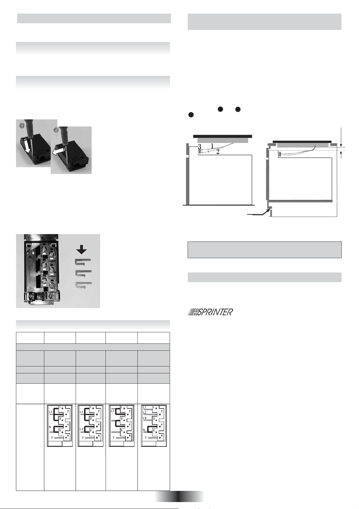
Single phase
220-240V~
Two phases
220-240 V2~
Three phases
220-240 V3~
Three phases
380-415 V3N~
25 A 25 A 20 A 16 A
PVD 633 - PVD 642 - PVD 644
PVD 633
PVD 642
PVD 644
L1: Phase
shunt 1-2 and
shunt 2-3
N: Neutral
shunt 4-5
T: Earth
CONNEC-
TION TO
THE
TERMIMAL
BLOCK
L1: Phase
shunt 1-2 end
shunt 2-3
L2: Phase
shunt 4-5
T: Earth
L1: Phase
shunt 1-2
L2: Phase
shunt 3-4
L3: Phase
T: Earth
L1: Phase
L2: Phase
L3: Phase
N: Neutral
shunt 4-5
T: Earth
L2
L3
3 G 2,5
H05VV-F or
H05RRF
3 G 2,5
H05VV-F or
H05RRF
4 G 2,5
H05VV-F or
H05RRF
5 G 1,5
H05VV-F or
H05RRF
CABLE
FUSE
20 A 20 A 20 A 16 APVD 640
25 A 25 A 25 A 16 A
PVD 742
PVD 646
Loading ...
Loading ...
Loading ...