Loading ...
Loading ...
Loading ...
12
to the Tone Arm. Reposition the Phono Cartridge
so the tip of the stylus is in the center of the small
circle and the Front and Sides of the Phono Car-
tridge are parallel to the lines on the Alignment
Gauge. Tighten up the mounting hardware and
verify the correct alignment.
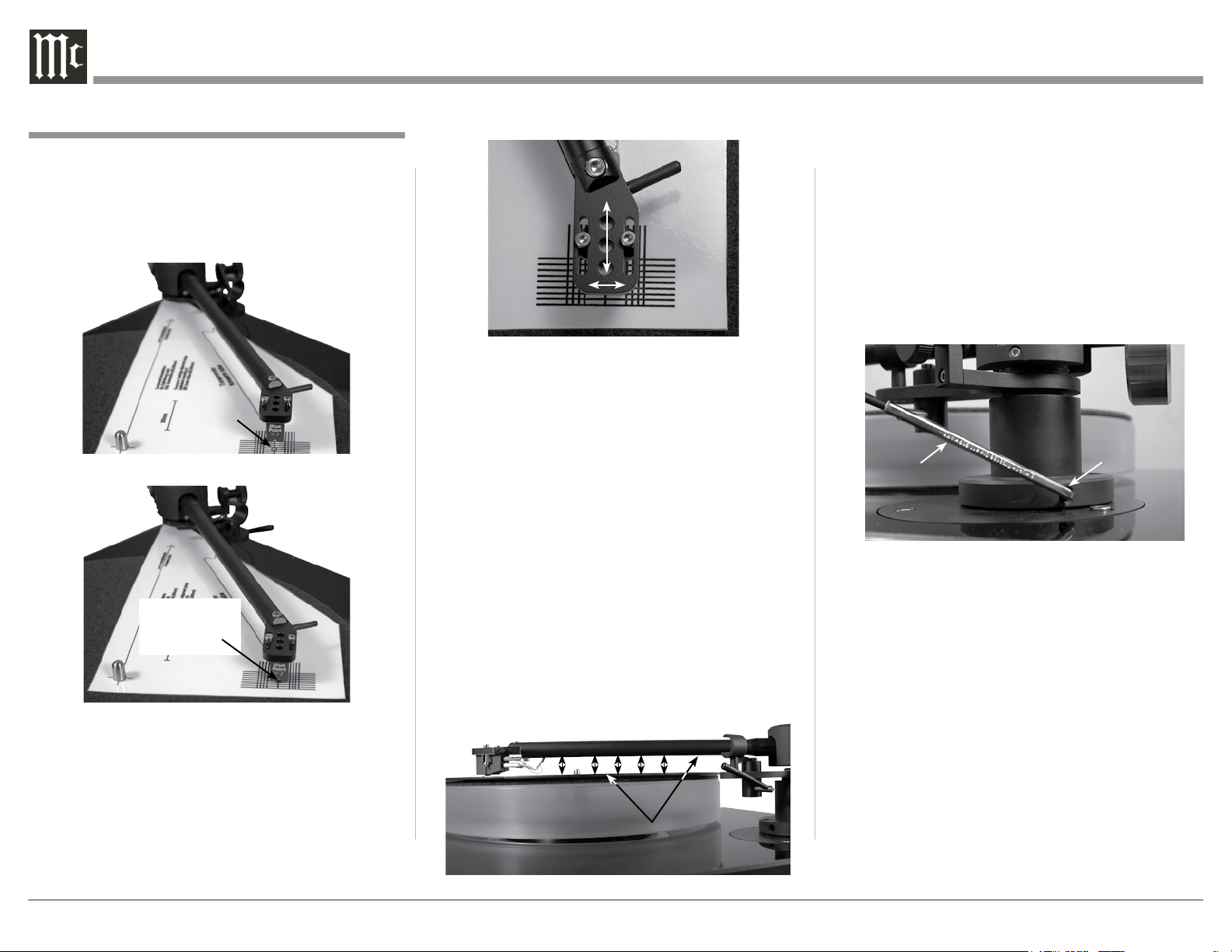
Tone Arm Height
To assure the best sound reproduction, it is very
important the MT5 Tone Arm is parallel to the record
surface during playback. The height of the Tone Arm
is adjustable to accommodate the different Phono Car-
tridge physical heights. To adjust for the proper Tone
Arm Height, perform the following the steps:
1. Release the Tone Arm from the Tone Arm Rest,
place it on a record and check to see if the Tone
Arm is parallel to the surface of the record. Refer to
figure 30. With the Tone Arm parallel, no adjust-
ment is needed and proceed to “Setting the Track-
ing Force Pressure”. If the Tone Arm is not parallel,
note whether the rear of the Tone Arm needs to go
up or down.
2. With the Tone Arm secured in the Tone Arm Rest,
carefully loosen the two set screws while sup-
porting the rear of the Tone Arm. Reposition the
Tone Arm based on findings in the previous step.
Temporarily tighten one of the set screws. Refer to
f igu re 31.
3. Release the Tone Arm from the rest and place it on
a record and check to see if the Tone Arm is now
parallel. Also check to make sure the Tone Arm is
parallel to the record platter and the right side of
the turntable base. Refer to figure 30.
4. With the Tone Arm parallel to the record surface,
record platter and turntable base, tighten both set
screws, which were loosened in step 2. If not, re-
peat steps 1, 2 and 3 until the Tone Arm is parallel.
Setting the Tracking Force Pressure
The MT5 is supplied with a Stylus Tracking Force
Gauge for checking and adjusting the Stylus Track-
ing Pressure. The Gauge uses the “Balance Scale”
methodology for measurement. Place the Gauge on
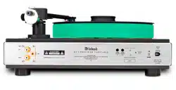
2. With the Anti-Skate Adjustment set to minimum
(refer to figure 37), carefully place the Tone Arm
onto the Alignment Gauge with the diamond tip of
the stylus on the center of the small circle located
between the parallel lines. Refer to figures 27
and 28.
Note: It may be necessary to slide the Phono Car-
tridge forwards or backward in the headshell to
position the stylus in the center of the circle.
3. It is important the Front and Sides of the Cartridge
Body line up with these parallel lines when look-
ing down over the top of the Tone Arm. Refer to
figures 28 and 29. If it is not parallel, loosen the
mounting hardware securing the Phono Cartridge
Tone Arm Adjustments, con’t
Figure 27
Location
of circle
Figure 28
Stylus Tip in
the center of
the circle
Figure 29
One of two
Tone Arm
Height Set
Screws
Allen
Wrench
Fig ure 31
Figure 30
The Tone Arm Height is adjusted for the
Arm to be parallel to the record surface
Loading ...
Loading ...
Loading ...