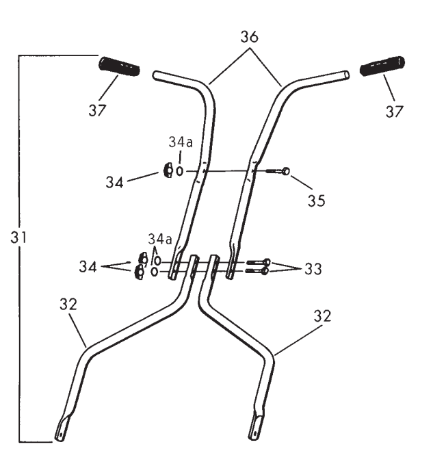
Enclosed in carton are the mower handle parts (2 upper handlebar pieces and 2 lower pieces) and hardware package (for contents, see back cover).
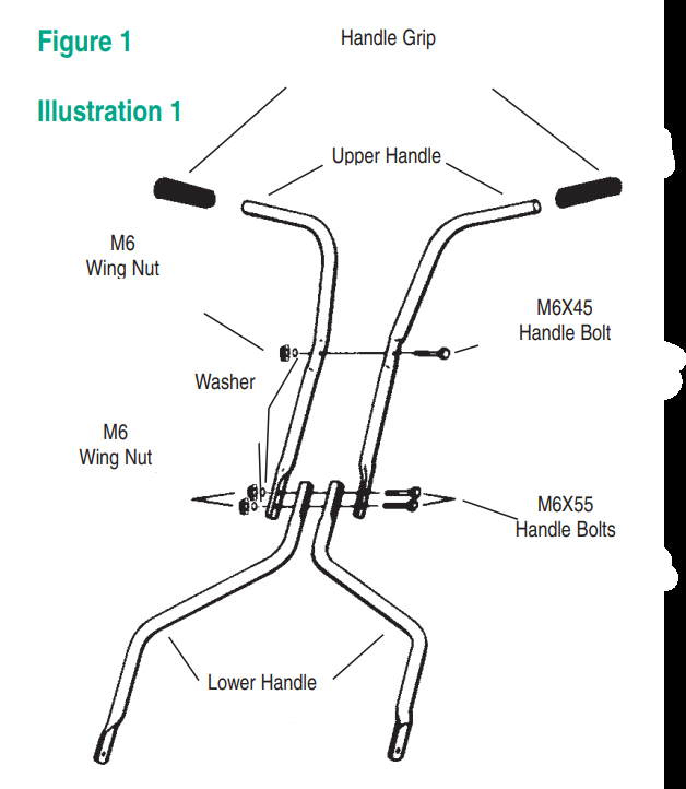
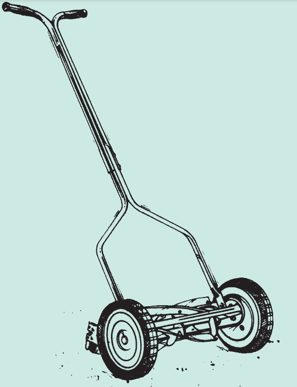
Lay out the parts of the handle as shown in figure 1.
Fasten the 2 lower handle pieces to the upper portion of the handle using the two (2) M6X55 bolts and wingnuts.
Fasten the 2 upper handlebar pieces together using the M6X45 bolt and wingnut.
Lubricate the inside of the 2 handle grips with soapy water (for easier application) and slide onto the handle.
Attaching the handle to the mower
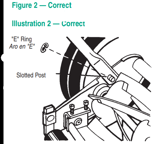
DO NOT attempt to attach the handle to the bolts on the roller assembly at the rear of the mower. This is incorrect! (refer to figure 3) As you follow the instruction below, refer to figure 2 for more information.
After assembling the handle, fit the holes at the end of the lower portion of the handle on the left and right side, over the short posts extending out from the side plates.
When the handle is in place over the posts, snap the “E” rings onto the slotted posts on both sides to prevent the handle from coming off.
WARNING: Some dust and debris created by the use of this tool could contain chemicals known to the State of California to cause cancer and birth defects or other reproductive harm.
Some examples of these chemicals are:
chemicals in fertilizers
compounds in insecticides, herbicides and pesticides
arsenic and chromium from chemically treated lumber.
Your risk from exposure to these chemicals varies, depending on how often you do this type of work. To reduce your exposure, work in a well-ventilated area and with approved safety equipment, such as dust masks that are specially designed to filter out microscopic particles.
Usage & Care
General Care
Minimum care is required to assure smooth operation of your mower.
To avoid damage to the mower or cutting blades, keep the area to be mowed free from any debris.
We suggest a routine application of oil or lubricant (i.e. WD-40). This should be applied to all cutting surfaces, the cutting reel axle shaft and wheels.
Minor cutting height adjustments
These units can be adjusted to offer a cutting height range from 1/2” to 2 1/2” (1.27 cm to 6.35 cm) simply by adjusting the roller assembly. Keep in mind that the same adjustment must be performed on both sides of the mower.
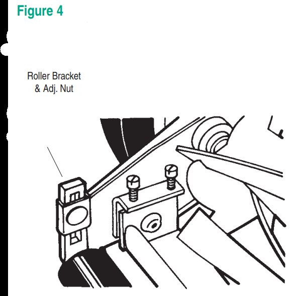
As you follow the instructions below, refer to figure 4 for more information.
To achieve the lowest cutting position, loosen and remove the nuts on both sides of the roller assembly.
Position the bolt through the bottom hole of the plastic roller bracket and the top hole of the mower side plate. Retighten nuts on both sides.
To achieve the highest cutting position, loosen and remove the nuts on both sides of the roller assembly.
Position the bolt though the top hole of the plastic roller bracket and the bottom hole of the mower side plate. Retighten nuts on both sides.
Other cutting heights can be obtained by positioning the bolts through other hole locations.
Precise cutting height adjustments
The wheel/dust cover assembly can be moved to one of 3 positions on the side plate. Keep in mind that the same adjustment must be performed on both sides of the mower.
As you follow the instructions below, refer to figure 5.
Remove the axle nut on the inside of the mower by holding the axle pin in place with either a 1/2" (1.27 cm) socket or flatblade screwdriver (depending on model type), (on 705 & 415, remove hub cap first) and either a socket or box-end wrench on the nut.
Pull the wheel, dust cover and axle pin out gently as a unit until the axle pin clears the side plate. Then, reposition in the desired hole, and replace and tighten nuts. Position A = 1/2" (1.27 cm) cutting height, position B = 1 3/4" (4.44 cm), position C = 2 1/2" (6.35 cm).
Mower blade adjustment
The blades have been preadjusted before leaving the factory
Misalignment can occur resulting in blades that are too loose or too tight. If this happens, you will notice a rough, uneven cut or a hard-pushing mower.
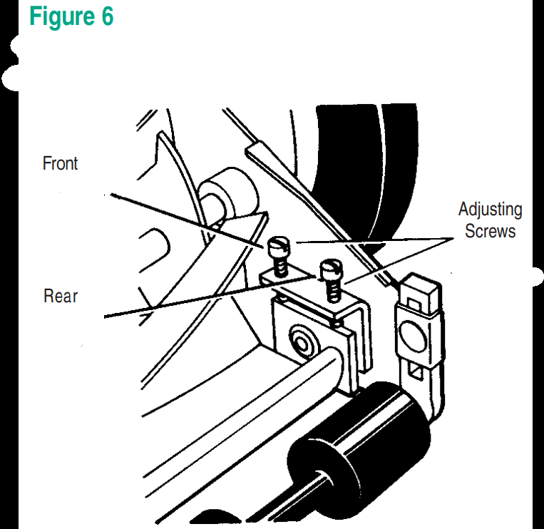
All adjustments are made from the rear of the mower (opposite from the bar with the logo decal). Each end of the cutting bar can be adjusted separately.
As you follow the instructions below, refer to figure 6 for more information.
The cutting bar blade (located under the reel) pivots. The front screws move the cutter bar away from the blades, while the rear screws move the cutter bar toward the blades.
Adjusting the screws is a very sensitive procedure. 1/16th of a turn is considered a major adjustment.
Before tightening one adjusting screw, be sure to loosen the opposing screw an equal amount.
Loosening the blades
The cutting bar blade must be moved further from the cutting reel.
Loosen both back screws equally by turning them counterclockwise.
Tighten both front screws equally by turning them clockwise.
Tightening the blades
The cutting bar blade must be moved closer to the cutting reel.
Loosen both front screws equally by turning them counterclockwise.
Tighten both back screws equally by turning them clockwise.
Checking adjustments
Turn mower upside down.
Insert piece of paper (i.e., writing or newspaper) between the cutter bar and the reel blades, and carefully turn the reel blades by hand.
All blades should slice the paper evenly the entire length of the cutter bar while the reel turns smoothly.
If the mower has an intermittent cut, adjustment should be made to appropriate side of the blades to attain proper cutting action.
Sharpening the cutting blades
When the mower is properly lubricated and adjusted, sharpening should not be necessary for several years. However, the following steps will allow you to do the procedure yourself at relatively little expense.
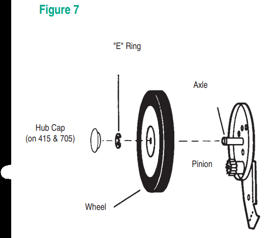
Remove the “E” rings, wheels and pinion from both sides of the mower (refer to figure 7).
Remove both pawls from the rectangular slots in reel shaft and reverse their positions (refer to figure 8).
Reverse the placement of the pinion gears.
Place the left pinion on the right end of the reel shaft and the right pinion on the left end of the reel shaft. Replace the wheels and “E” rings.
Spread a thin layer of lapping compound on the front edge of the reel blades.
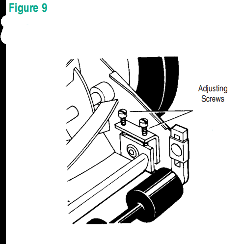
Adjust the cutter bar so that the cutter bar blade has light but firm contact with the reel blades across the full width of the cutter bar (refer to figure 9). CAUTION: Do not overtighten the adjusting screws, as this could damage the cutter bar. Both screws must be tight on the final adjustment.
Push the mower backward on a smooth surface (such as a sidewalk or paved driveway). Continue to do this until the reel blades rotate relatively free and front edge of the cutter bar blade is polished.
Remove wheels; reverse pinions and pawls so that the beveled edge of the pawl is on the right. CAUTION: Clean any grinding compound or debris from the cutter bar blade, reel blades, pinions and pawls. Lubricate axle and pinion with a light film of wheelbearing grease and replace wheels and “E” rings.
NOTE: It is recommended to use an industrial or valve lapping compound between 100-240 grit. This is usually available at an industrial or automotive supply store. If professional sharpening is required, consult your local yellow pages for lawn mower repair services.
How to order parts
Specify the following information when ordering parts:
Complete model number (found on the identification decal on the rear of the cutter bar).
Color of the parts you are ordering.
Cutting width of your unit.
If you are uncertain of the number of the part to be replaced, you can make sure to receive the exact part(s) you need by mailing the broken part(s) prepaid to the factory along with your order. Be sure that when you are sending parts to enclose your name, address and telephone number in the package.
ALL PARTS ARE SOLD FACTORY DIRECT. MINIMUM CHARGE FOR ANY ORDER IS US$2.00 EXCLUDING SHIPPING. ALL SHIPPING CHARGES ARE THE RESPONSIBILITY OF THE PURCHASER.
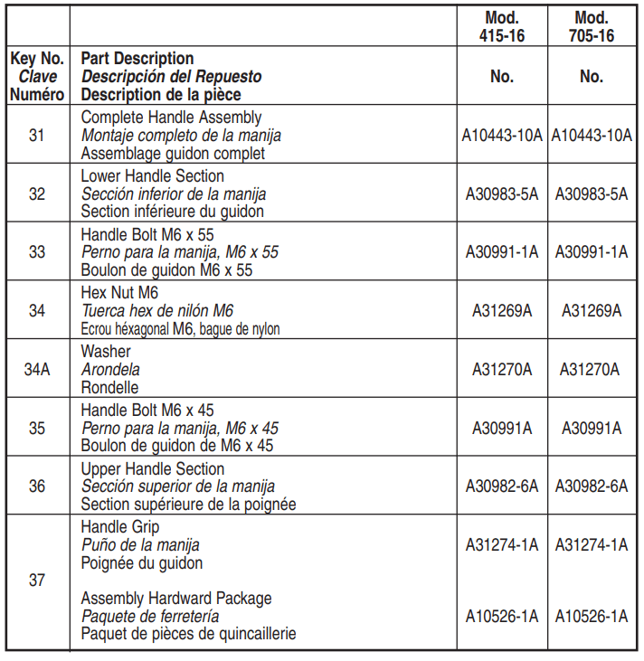
Mower Parts
Part Nos. & ID Guide
Mod.415-16
Mod.705-16
Key No.
Part Description
No.
No.
1A
Ball Cup
A30122A
A30122A
1B
Ball Cup
A31203A
A31203A
2
Ball Bearing Assembly
A30137A
A30137A
3
Bearing Cone
A31199A
A31199A
4
Spring, reel adjustment
31202-1
31202-1
5
Dust Washer
A31200A
A31200A
6
Bearing Washer
A31201A
A31201A
7
Ratchet Pawl
A30316A
A30316A
8
Reel Assembly (key #3-6)
A10506-1A
A10507-1A
9
Snap Ring, Axle
A30317-1A
A30317-1A
10
Hub Cap
A30926-1A
A30926-2A
11
Axle
A30337A
A30337A
11A
Hex Nut, M10
A30733A
A30733A
12
Wheel
-
-
13
Tire
-
-
13A
Wheel and Tire Assembly
10446P
10426-1P
14
Hex Head Bolt
A30660A
A30660A
15
Cover Plate
A30730A
A30730A
16
Left Side Plate
A10508-1A
A10508-1A
16A
Right Side Plate
A10326-16A
A10326-16A
17
Retaining Ring
A30990A
A30990A
18
Torsion Bar
A10490A
A10490A
19
Left Pinion Gear
A30737-3A
A30737-3A
20
Adjustment Screw (incl. in 16 & 16A)
A30300A
A30300A
21
Right Pinion Gear
A30737-2A
A30737-2A
22
Cutter Bar Bolt M10 x 30
A31039A
A31039A
23
Wing Nug
A31043A
A31043A
24
Roller Bracket
A30321A
A30321A
25
Carriage Bolt M8 x 25
A30119-5A
A30119-5A
26
Cutter Bar
A10305-2A
A10305-2A
26A
Cutter Bar Stud
(incl. in nos. 16 & 16A)
A30519A
A30519A
27
Roller Section
A31195A
A31195A
28
Roller Spacer
A30071-8A
A30071-8A
29
Roller Tube
Complete Roller Assembly
A30319-2A
A10510A
A30319-2A
A10510A
30
Roller Bracket Clamp
31321
31321
SAFETY RULES
Read all instructions in this manual before using mower.
Inspect your lawn for any debris or foreign objects and remove them before mowing.
Never place your hands, fingers, or feet inside the reel. Although not powered by a motor, when the wheels turn, the reel cuts.
Never mow when the grass is wet enough to be slippery.
Don’t place your hands or feet near a moving part of the mower.
Don’t operate the mower while barefoot or wearing sandals.
Walk slowly, never run. Always be sure of your footing when operating the mower.
Never intentionally strike or ram trees, fences, etc. This can cause injuries or severely damage the mower.
Remember that this mower is a precision piece of lawn care equipment. Treat it as such by exercising caution when using it.
Make sure your mower is in safe operating condition. Don’t attempt to operate the mower if it is damaged; have it repaired first.
California Proposition 65 Warning:
This product contains chemicals known to the State of California to cause cancer, birth defects or other reproductive harm.
#1 Will this operate both pushing it forward and pulling it backwards, or does it only cut when moving in the forward direction?
This mows forward only. When it needs to be sharpened, you spin its wheels backwards against the cutting bar, after removing the wheel and gear - allowing you to turn forwards or backwards to spin the cylinder of blades (instructions are all over the web and included in the sharpening kit).
#2 Back wheels keep lifting off the ground when the mower is pushed. Any way to prevent this?
The back wheels cause the front to lift up?? Then your pushing angle is too low. The big wheels are the driving wheels. Going up hills and pushing too low will cause the front to lift up and not keep cutting...
#3 My yard is a little sloped and the ground is a little uneven (bumpy). Does anyone know if this mower will work well with that kind of lawn?
My yard is a bit flatter but has some bumpy uneven spots. It works ok. The only problem you'll have with this mower is hitting weeds, the mower DOES NOT DO weeds. Blades are very sharp though and I was surprised at performance to cut the yard...
#4 How important are the e-rings, really? Because mine fell under the porch and there's no way I'm crawling through all those spider webs to get it.
You can probably get another one at a hardware store. I'm sure the ring is suppose to hold the handle in place.