Loading ...
Loading ...
Loading ...

4
3C. ATTACH WIRING USING A SUB-BASE
AND CHASEWAY (sold separately)
1. Remove the rectangular knockout at the bottom of
the junction box. Remove the rectangular knockout
at the right end of the sub-base.
2. Wiring is placed between the two halves of
the chaseway. Observe the orientation of the
chaseway.
3. Align the screw holes and secure the halves
together by using a Type A screw in the lower or
longer section of the chaseway. The top screw
must be inserted in the next step.
4.
Slide the upper end of chaseway with wiring protruding
into rectangular knockout opening in the junction box.
Be sure chaseway side flanges are on the inside of the
box. Drive one screw (provided with chaseway) through
the junction box bottom into the chaseway side flange*.
Insert lower end of chaseway into rectangular hole in
sub-base and slide to right into the rectangular knockout
making sure chaseway side flanges are inside the sub-
base. Route wire toward the center of the sub-base.
Drive one screw (provided with sub-base/chaseway kit)
through the sub-base slotted hole into chaseway side
flange hole.
* Align the upper screw holes and use a Type A screw to
complete the chaseway assembly.
Installation Instructions
3A. SELECT ELECTRICAL
CONNECTION METHOD
• For Conduit Installation: Use the hole in the bottom
of the junction box to connect flexible conduit. Hole
is designed for 1/2” connector. Proceed to Step 3B.
• For Sub-Base Installation: Remove the rectangular
knockout in the bottom of the junction box base to
accept the chaseway from the sub-base. Proceed to
Step 3C.
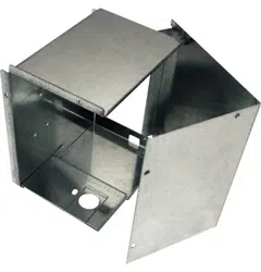
STEP 3: INSTALL JUNCTION BOX ON MOLDED PLASTIC BMC
CONTROL BOX COVER
Screw
Tab
Junction Box
Base
Rectangular
knockout
3B. ATTACH WIRING USING A
CONDUIT
1. Use the round hole at the bottom of the junction box to
attach conduit coming from the branch circuit. Attach
the conduit using proper conduit connector and bring
wires into the junction box. Leave 6” of wire free at the
end of the conduit to allow connections to be made.
2. If a fuse and fuse holder are to be used, the
knockout at the side of the box is for mounting
a Buss Fuse holder. Be sure the fuse and fuse
holder are of the same rating as the branch circuit.
Leadwires at the fuse can be either soldered in
place or attached using UL-listed 1/4” female
(receptacle) crimp connectors.
Conduit
Knockout
Sub-base
Wiring
Chaseway cover
Chaseway
Ground wire
Loading ...
Loading ...
Loading ...