Loading ...
Loading ...
Loading ...
TESTING –
IMPORTANT! Do not test or run disposer dry as this will damage the seal and void the warranty.
1. Test assembly for leaks: a. where cone joins table b. where disposer joins cone c. all piping connections d. “Swirl Spray” fittings
2. After plumbing and electrical connections are made, turn on disposer to be sure all parts are in working order and that the disposer turntable
rotates clockwise when viewed from above. Open valve in vacuum breaker line, and using valves in plumbing assembly (Fig.7), adjust so
that water swirls around just below the rim of the cone sink. Leave valves in these positions. These combinations provide a flow of approxi-
mately 8 gallons of water per minute.
3. Replace cover, retest for leaks and turn unit off.
4. Unit is now ready for operation.
560P333P01 REV B
4240 E. La Palma Avenue, Anaheim, CA 92807 • (800) 454-4423 • fax (800) 246-3245 • www.wasteking.com
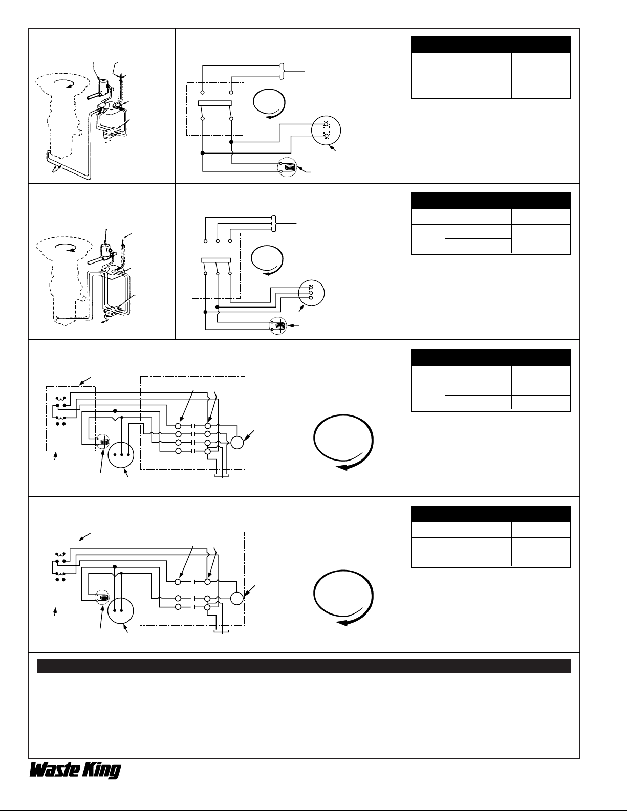
MANUAL SWITCH
MODEL VOLTS WK PART NO.
500 –
110-120
2420
1500
220-240
FIG. 12 SINGLE PHASE FIG. 13 WIRING FOR SINGLE PHASE
UNITS WITH MANUAL SWITCH
FIG. 14 THREE PHASE FIG. 15 WIRING FOR THREE PHASE
UNITS WITH MANUAL SWITCH
FIG. 16 WIRING FOR THREE PHASE UNITS WITH MAGNETIC SWITCH
FIG. 17 WIRING FOR SINGLE PHASE UNITS WITH MAGNETIC SWITCH
NOTES:
1. Motor wired at Factory for 220-240
volts except for 1/2 HP. For 110-120
volts, connect motor wires as shown
inside of motor junction box cover.
MANUAL SWITCH
MODEL VOLTS WK PART NO.
500 –
208-240
2420
1500
460
NOTES:
1. Motor wired at Factory for 208-240 volts.
For 460 volts, connect motor wires as
shown inside of motor junction box cover.
2. Interchange T1 and T3 to reverse rota-
tion.
MAGNETIC SWITCH
MODEL VOLTS WK PART NO.
750 –
208-240 2416
1500
460 2417
NOTES:
1. Motor wired at Factory for 208-240 volts.
For 460 volts, connect motor wires as
shown inside of motor junction box cover.
2. Interchange T1 and T3 to reverse rotation.
3. No heaters used with magnetic switch.
MAGNETIC SWITCH
MODEL VOLTS WK PART NO.
500 –
110-120 2414
1500
220-240 2415
NOTES:
1. Motor wired at Factory for 220-240
volts except for 1/2 HP. For 110-120
volts, connect motor wires as shown
inside of motor junction box cover.
2. No heaters used with magnetic switch
L-1 L-2
T-1 T-2
L-1 L-2
T-1
T-2
L-3
T-3
T-3
L-3
T-2 L-2
32
T-1
L-1
THESE TERMINALS MAY BE
LABELED T4 OR L4
CLOCKWISE
ROTATION
CLOCKWISE
ROTATION
CLOCKWISE
ROTATION
CLOCKWISE
ROTATION
COMMERCIAL
®
by Anaheim Manufacturing
CLOCKWISE
ROTATION
WHITE WIRE
HOT WIRE
POWER “IN”
SOLENOID
VALVE
ON / OFF
POWER SUPPLY -
FUSE PER
LOCAL CODE
SOLENOID RATED VOLTAGE
TO MATCH LINE VOLTAGE
MOTOR JUNCTION BOX
TURNTABLE ROTATION
AS VIEWED FROM THE TOP
POWER SUPPLY -
FUSE PER
LOCAL CODE
SOLENOID RATED VOLTAGE
TO MATCH LINE VOLTAGE
MOTOR JUNCTION BOX
TURNTABLE ROTATION
AS VIEWED FROM THE TOP
TURNTABLE ROTA-
TION
AS VIEWED
FROM THE TOP
TURNTABLE ROTA-
TION
AS VIEWED
FROM THE TOP
CLOCKWISE
ROTATION
3 PHASE
POWER
LINE
JUNCTION
BOX
3 POLE
SWITCH
SOLENOID
VALVE
ON / OFF
L1 L2
T1 T2
L1 L2 L3
T1 T2 T3
SWITCH START - STOP
(MOUNT NEAR UNIT)
COIL RATED
VOLTAGE TO
MATCH LINE
VOLTAGE
POWER SUPPLY - FUSE PER LOCAL CODE.
MOTOR: CONSULT CHART FOR COR-
RECT MAGNETIC SWITCH
SOLENOID-RATED
VOLTAGE TO MATCH
LINE VOLTAGE
SWITCH BOX ON
FRONT OF UNIT
START
STOP
T-2 L-2
32
T-1
L-1
THESE TERMINALS MAY BE
LABELED T4 OR L4
SWITCH START - STOP
(MOUNT NEAR UNIT)
COIL RATED
VOLTAGE TO
MATCH LINE
VOLTAGE
POWER SUPPLY - FUSE PER LOCAL CODE.
MOTOR: CONSULT CHART FOR COR-
RECT MAGNETIC SWITCH
SOLENOID-RATED
VOLTAGE TO MATCH
LINE VOLTAGE
SWITCH BOX ON
FRONT OF UNIT
START
STOP
JUNCTION
BOX
SWITCH
BOX AND
COVER
ALL VOLTAGES – DO NOT USE L3 OR
T3 FOR SINGLE PHASE APPLICATION
®
Loading ...
Loading ...
Loading ...