Loading ...
MOUNTING DISPOSER –
Continued (Refer to Figure 6)
4. Attach a nut by two or three threads to screw and then attach another nut to screw on the opposite side of disposer. Finger-tighten two
screws to hold unit in place. Attach remaining four nuts to screws and finger-tighten evenly.
5. Check alignment with plumbing. Adjustment in alignment to plumbing can be made by rotating the unit carefully before tightening the nuts.
To assist in rotating unit, raise the unit from the bottom of the motor to relieve weight.
6. With the unit in its proper position, proceed to tighten six nuts evenly.
PLUMBING INSTALLATION
IMPORTANT! Before installing the Waste King disposer, the connecting waste line must be cleaned out to
the connecting sewer main.
MAKE ALL PLUMBING AND ELECTRICAL CONNECTIONS ACCORDING TO LOCAL CODES.
Recessed thread fittings must be used throughout and all pipe ends should be carefully reamed.
1. For spray-rinse with vol-temp, run a 1/2” hot water line to point indicated in Figure 7. Connect to spray-rinse globe valve, hot water side.
At no time should hot water be connected directly to disposer or cone sink.
2. Run a 1/2” cold water connection to point indicated in Figure 7.
3. Install solenoid valve in line, in upright (coil side up) position as shown in Figure 7, with arrow on side pointing in direction of water flow.
4. Install syphon breaker as in Figure 7. CHECK LOCAL CODE.
5. Make connection to water inlet fitting of cone sink. See Figure 7.
6. Make 1/2” cold water connection to spray-rinse globe valve, cold water side. This must be separate cold water line. Do not tee off of line to
cone unless a 3/4” line is furnished to assembly location. See Figure 7.
7. Assemble swirl spray(s) as shown in Figure 9. The assembly method for the swirl spray(s) is the same for all models. Other combinations
of convertible and fixed swirl spray(s) are optional. The outlet hole of the fixed swirl spray should be horizontal to promote vortex action in
the cone.
NOTE: The convertible spray should be easily adjustable by the operator to function as a swirl spray or as a dish-washing flume. Avoid
excessive tightening of nut or lock nut.
8. Connect 1/2” pipe to swirl spray as shown in Figure 7.
9. The disposer is equipped with a drain outlet designed for a slip-joint connection to a conventional 1
1
/
2” trap (not furnished). Connect the trap
with a branch waste line running directly into the sewage connection (Figure 7). Do not connect into a grease trap. A minimum slope of
1
/4”
per foot of run of waste line is recommended. Limit 1
1
/2” drain line to a 15-foot run, free of turns. A minimum number of elbows, tees, etc.,
reduce the possibility of plumbing stoppages. If unusual sewer conditions exist (too many bends, main too long, low water pressure resulting
in low flow rate*, or if a high percentage of food waste is leafy and/or paper), the use of a time delay relay and water injector into sewer is
suggested. Under such conditions, additionally, a larger size cold water line, larger solenoid valves and larger syphon breakers should be
used to overcome potential stoppages. (Parts and data available from factory.)
*Minimum cold water flow rate used with Models 500 through 1500: 5 gallons per minute or enough to push waste through pipeline
into the sewer.
TIP: Water volume adjustment: The top of the swirling water should occasionally crest to the body of the swirl water inlet.
10. To use the optional supplementary water connection, see Figure 8.
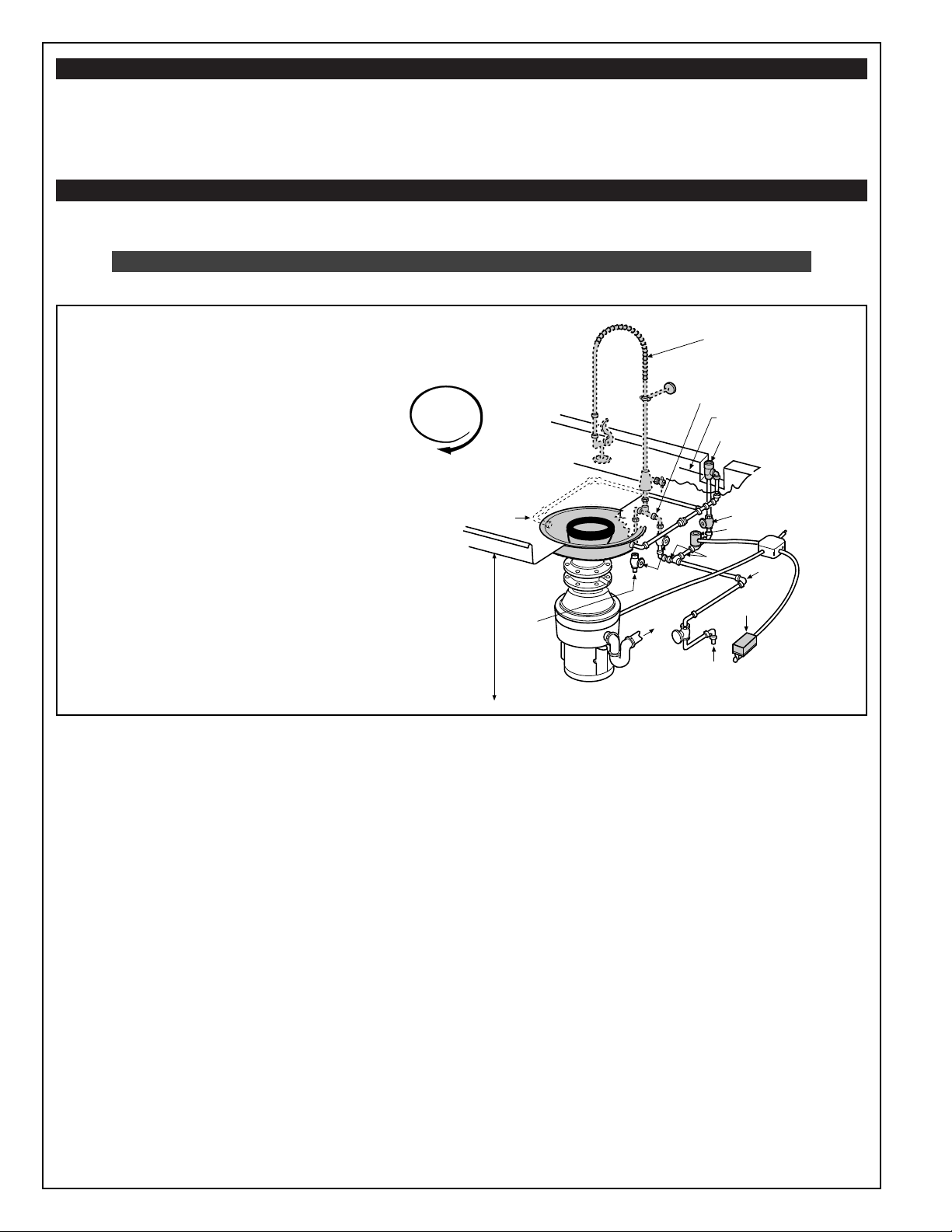
FIG. 7 CONE ASSEMBLY (Typical Installation)
NOTE:
A globe valve, if used for metering flow, must
be installed between solenoid valve and disposer.
See metering valve Fig. 7. Any valve ahead of the
solenoid valve must be opened and cause no
restrictions.
IMPORTANT! Do not test or run disposer
without minimum water flow (see Plumbing
Installation) as this will damage the seal and
void the warranty.
MINIMUM WATER FLOW RATE
5 GALLONS PER MINUTE WHILE IN USE
NOTE:
BASE UNIT INCLUDES DISPOSER, MOUNTINGS,
AND DRAIN OUTLET. OTHER ITEMS SHOWN IN
GRAY IN FIGURE 7 ARE AVAILABLE IN EQUIP-
MENT GROUPS ORDERED SEPARATELY.
#9 SPRAY RINSE (OPTIONAL)
VOL-TEMP ASSEMBLY
(included with 9T)
1" MIN. ABOVE TABLE RIM
CHECK CODE
1/2" SYPHON BREAKER
1/2" GLOBE VALVE
(for metering flow)
1/2" SOLENOID VALVE
3/4"
SWITCH
3/4" COLD
WATER SUPPLY
1/2" HOT
WATER
SUPPLY
GLOBE
VALVE
1-1/2"
WASTE
LINE
DISHTABLE OR
DRAIN BOARD
RIM TO FLOOR
STANDARD 34"
1/2"
SPRAY CONE
FITTINGS
CLOCKWISE
ROTATION
Looking from top.
Loading ...
Loading ...
Loading ...