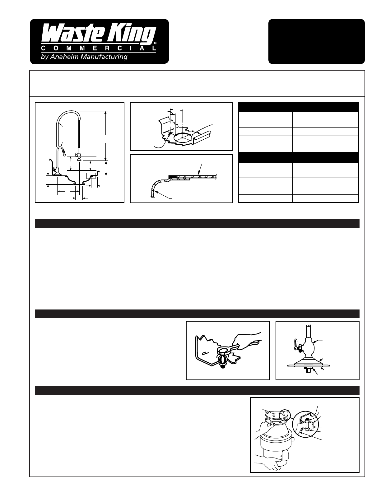
INSTALLATION OF CONE SINK INTO DISH OR WORKTABLE
1. (See Figures 1 and 2.) Locate hole center as shown on Figure 2. Cut a “C” (Figure 2) diameter hole in dish or work table, a minimum of 2”
from the inside front edge (operator’s side). Hole can be cut with a “nibbler” after a knockout hole 1-1/2” diameter has been punched.
2. Lift cone to underside of table with cone flange overlapping all around (Figures 1 and 3).
3. Check alignment of cone spray fittings to be sure they are in the proper position. For 15” and 18” cones, position such that holes are located
to right and left side of operator. (See Figure 7 for location.)
4. Tack weld, spot weld, bolt, or rivet flange of cone sink to underside of dish or work table. If bolted or riveted, smooth top surface and wash-
solder around bolt or rivet heads and sand smooth.
5. Bead weld or solder and wash-solder all around where the table joins flange of cone sink for a clean, watertight, sanitary installation.
6. The cone sink has been designed with the step, as shown in Figure 3. In the welding or soldering operation required to assemble the cone
sink to the dish or work table, every attempt should be made to keep the recessed, flat portion of the cone free of the welded or solder mate-
rial. This will minimize the clean-up time required and provide a smooth, flat surface for any cover.
SPRAY-RINSE INSTALLATION
1. Locate center (Figures 1 and 2).
2. Drill 7/16” diameter hole through center.
3. Assemble 7/8” punch and tighten bolt head, as shown in
Fig. 4, until the die pierces the stainless steel, leaving a
clean opening of 7/8”.
4. Place body valve and base in position, assemble washer
and locknut as shown in Figure 5.
5. Attach vol-temp assembly to the projecting nipple, as
shown in Figure 7.
MOUNTING DISPOSER
For models to be installed in sink with 3-1/2” outlet,
see separate sheet enclosed for mounting instructions.
1. Clamp ring taped to top side of Hush Cushion
®
should be placed on underside of
top flange of Hush Cushion
®
. Line up holes in clamp ring with holes in Hush Cushion
®
and insert six screws also contained in plastic bag. Insert through clamp ring and
Hush Cushion
®
from the underside.
2. Line up holes in loose steel clamp ring on cone sink with screws in Hush Cushion
®
and raise disposer into position with screws matching holes in clamp ring in approximate
position with plumbing drain outlet.
3. To manually raise the disposer into position, lift the unit by grasping the disposer with
one hand from the bottom of the motor, and with the other hand around the Hush
Cushion
®
, guide the unit into position, as shown in Figure 6.
COMMERCIAL
DISPOSER MODELS
500, 750, 1000,
1250, 1500
INSTALLATION
INSTRUCTIONS
BEFORE INSTALLING, READ ENTIRE INSTRUCTIONS CAREFULLY.
RISK OF INJURY TO PERSONS FROM HAZARDOUS MOVING PARTS. SERIOUS INJURY POSSIBLE IF
NOT PROPERLY INSTALLED WITH A HOPPER OR A CONE SPECIFIED IN THE INSTRUCTION MANUAL.
IF YOU ARE REPLACING AN OLD DISPOSER GO TO
MOUNTING DISPOSER
MODEL 6T
2216 2215 2211
12” CONE 15” CONE 18” CONE
A 10
1
/4”11
3
/4”13
1
/4”
B 3
1
/2”3
1
/2”3
1
/2”
C 13
1
/2
”16
1
/2
”19
1
/2
”
MODEL 9T
2216 2215 2211
12” CONE 15” CONE 18” CONE
A 12
7
/8
”12
7
/8
”12
7
/8
”
B 6
1
/8”4
5
/8”3
1
/8”
C 13
1
/2”16
1
/2”19
1
/2”
FIG. 1 FIG. 2
FIG. 4 FIG. 5
FIG. 3
CO
N
FIG. 6
CONE SINK
NUT
CLAMP RING
CLAMP RING
MOUNT SCREW
HUSH CUSHION
BODY VALVE
7/8” PUNCH
BASE
WASHER
LOCKNUT
DISH TABLE
CONE SINK
APPROX.
30”
APPROX. 14”
9” MIN.
6” MIN.
2” TO 4”
6”
A
6-5/8”
No. 9T
SPRAY
RINSE
No. 6T
SINK
HOLE
C DIA.
SPRAY
RINSE
HOLE
A
B
LOCKNUT
MOUNTING DISPOSER –
Continued (Refer to Figure 6)
4. Attach a nut by two or three threads to screw and then attach another nut to screw on the opposite side of disposer. Finger-tighten two
screws to hold unit in place. Attach remaining four nuts to screws and finger-tighten evenly.
5. Check alignment with plumbing. Adjustment in alignment to plumbing can be made by rotating the unit carefully before tightening the nuts.
To assist in rotating unit, raise the unit from the bottom of the motor to relieve weight.
6. With the unit in its proper position, proceed to tighten six nuts evenly.
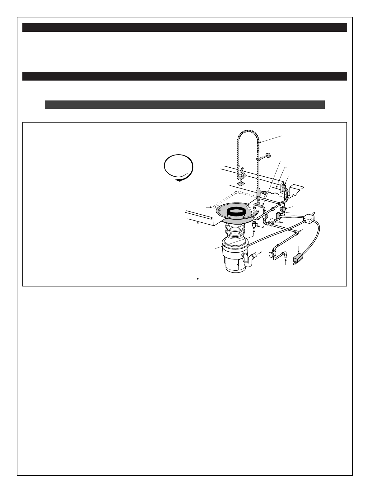
PLUMBING INSTALLATION
IMPORTANT! Before installing the Waste King disposer, the connecting waste line must be cleaned out to
the connecting sewer main.
MAKE ALL PLUMBING AND ELECTRICAL CONNECTIONS ACCORDING TO LOCAL CODES.
Recessed thread fittings must be used throughout and all pipe ends should be carefully reamed.
1. For spray-rinse with vol-temp, run a 1/2” hot water line to point indicated in Figure 7. Connect to spray-rinse globe valve, hot water side.
At no time should hot water be connected directly to disposer or cone sink.
2. Run a 1/2” cold water connection to point indicated in Figure 7.
3. Install solenoid valve in line, in upright (coil side up) position as shown in Figure 7, with arrow on side pointing in direction of water flow.
4. Install syphon breaker as in Figure 7. CHECK LOCAL CODE.
5. Make connection to water inlet fitting of cone sink. See Figure 7.
6. Make 1/2” cold water connection to spray-rinse globe valve, cold water side. This must be separate cold water line. Do not tee off of line to
cone unless a 3/4” line is furnished to assembly location. See Figure 7.
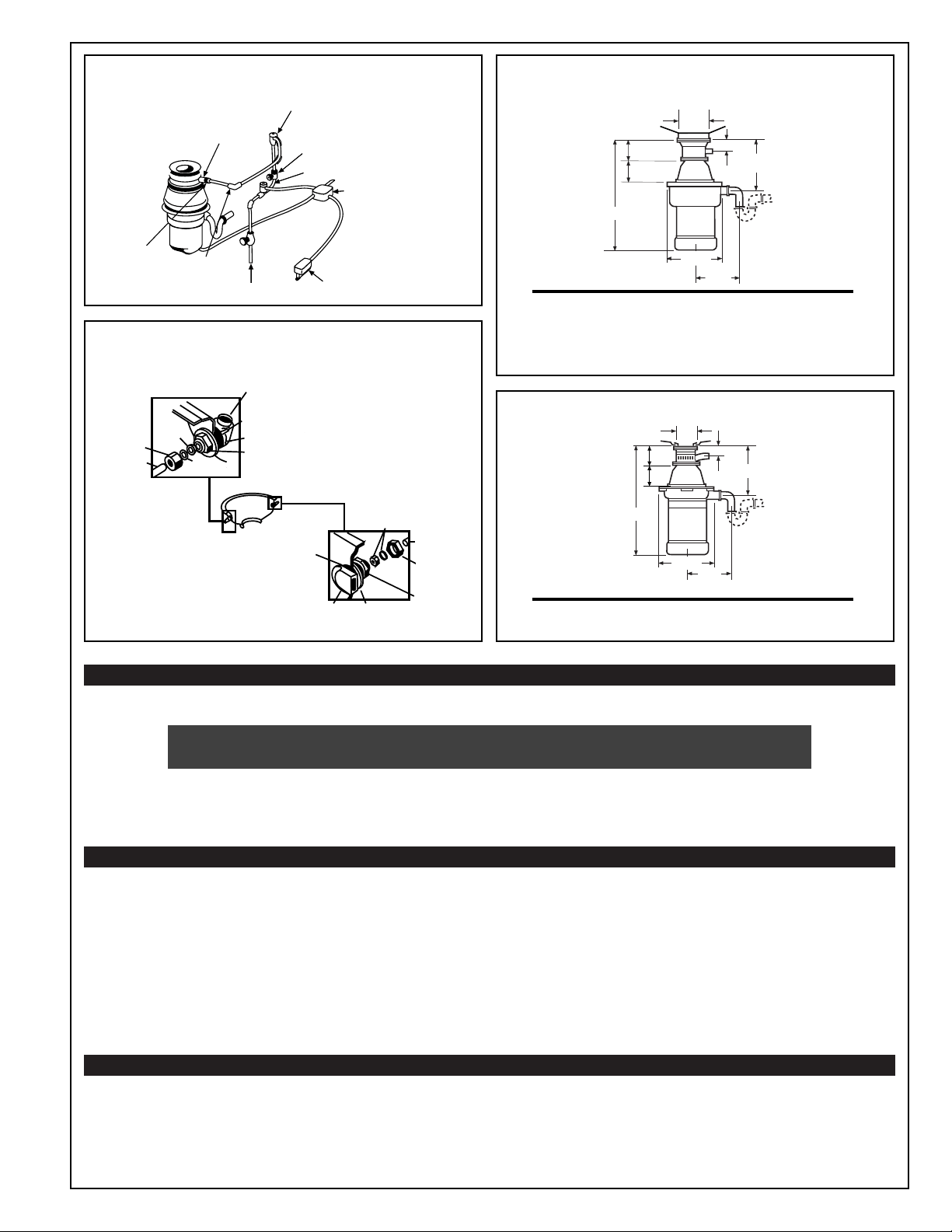
7. Assemble swirl spray(s) as shown in Figure 9. The assembly method for the swirl spray(s) is the same for all models. Other combinations
of convertible and fixed swirl spray(s) are optional. The outlet hole of the fixed swirl spray should be horizontal to promote vortex action in
the cone.
NOTE: The convertible spray should be easily adjustable by the operator to function as a swirl spray or as a dish-washing flume. Avoid
excessive tightening of nut or lock nut.
8. Connect 1/2” pipe to swirl spray as shown in Figure 7.
9. The disposer is equipped with a drain outlet designed for a slip-joint connection to a conventional 1
1
/
2” trap (not furnished). Connect the trap
with a branch waste line running directly into the sewage connection (Figure 7). Do not connect into a grease trap. A minimum slope of
1
/4”
per foot of run of waste line is recommended. Limit 1
1
/2” drain line to a 15-foot run, free of turns. A minimum number of elbows, tees, etc.,
reduce the possibility of plumbing stoppages. If unusual sewer conditions exist (too many bends, main too long, low water pressure resulting
in low flow rate*, or if a high percentage of food waste is leafy and/or paper), the use of a time delay relay and water injector into sewer is
suggested. Under such conditions, additionally, a larger size cold water line, larger solenoid valves and larger syphon breakers should be
used to overcome potential stoppages. (Parts and data available from factory.)
*Minimum cold water flow rate used with Models 500 through 1500: 5 gallons per minute or enough to push waste through pipeline
into the sewer.
TIP: Water volume adjustment: The top of the swirling water should occasionally crest to the body of the swirl water inlet.
10. To use the optional supplementary water connection, see Figure 8.
FIG. 7 CONE ASSEMBLY (Typical Installation)
NOTE:
A globe valve, if used for metering flow, must
be installed between solenoid valve and disposer.
See metering valve Fig. 7. Any valve ahead of the
solenoid valve must be opened and cause no
restrictions.
IMPORTANT! Do not test or run disposer
without minimum water flow (see Plumbing
Installation) as this will damage the seal and
void the warranty.
MINIMUM WATER FLOW RATE
5 GALLONS PER MINUTE WHILE IN USE
NOTE:
BASE UNIT INCLUDES DISPOSER, MOUNTINGS,
AND DRAIN OUTLET. OTHER ITEMS SHOWN IN
GRAY IN FIGURE 7 ARE AVAILABLE IN EQUIP-
MENT GROUPS ORDERED SEPARATELY.
#9 SPRAY RINSE (OPTIONAL)
VOL-TEMP ASSEMBLY
(included with 9T)
1" MIN. ABOVE TABLE RIM
CHECK CODE
1/2" SYPHON BREAKER
1/2" GLOBE VALVE
(for metering flow)
1/2" SOLENOID VALVE
3/4"
SWITCH
3/4" COLD
WATER SUPPLY
1/2" HOT
WATER
SUPPLY
GLOBE
VALVE
1-1/2"
WASTE
LINE
DISHTABLE OR
DRAIN BOARD
RIM TO FLOOR
STANDARD 34"
1/2"
SPRAY CONE
FITTINGS
CLOCKWISE
ROTATION
Looking from top.
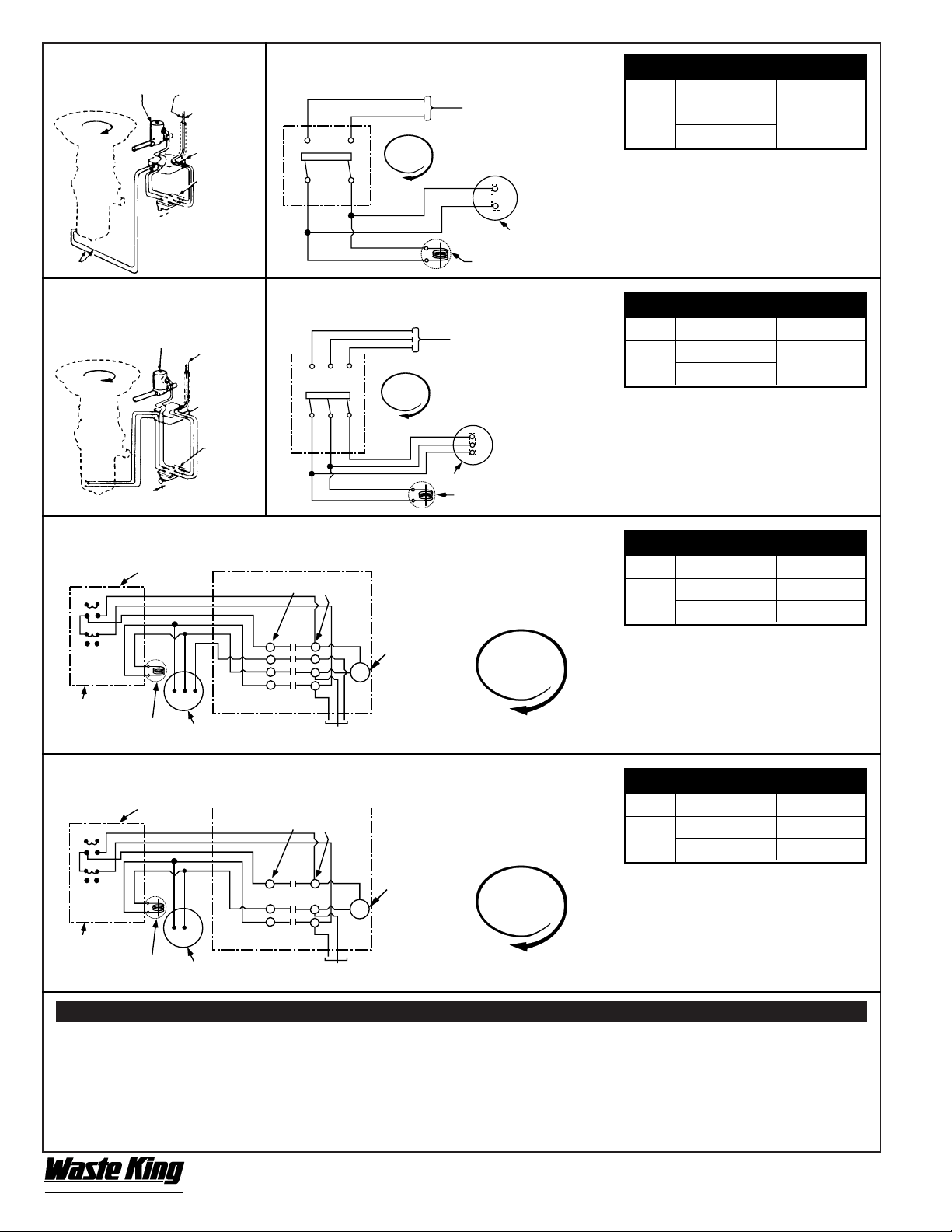
ELECTRICAL CONNECTIONS
All electrical connections must be made in accordance with local wiring codes Flexible BX cable should be used in making electrical
connections to motor to avoid transmission of noise. Be careful not to pinch wires when replacing terminal box.
IMPORTANT! THE WASTE KING COMMERCIAL DISPOSER MUST BE CAREFULLY
AND PERMANENTLY GROUNDED. GROUND SCREW IS PROVIDED.
Overload Protection: Reset button overload provided on all standard models.
IMPORTANT NOTE: Disposer motor phase, single or three phase, must be the same as power source and line phase.
Disposer wiring connection voltage must be the same as the voltage of power source.
ALL SINGLE PHASE MOTORS
3-Pole, 20 Amp., heavy duty switch encased in waterproof receptacle. Two poles of switch control motor and third pole controls solenoid, isolat-
ing the two circuits to prevent solenoid kickback when switch is turned off. Refer to Figures 12 and 13 for recommended wiring installation.
SINGLE PHASE 1/2 HP
Factory Wired for 110-120-V A.C. unless otherwise specified. To connect for 220-240-V A.C. refer to information on inside face of
terminal box cover.
SINGLE PHASE
3
/4 HP, 1HP, 1
1
/4 HP, and 1
1
/2 HP
Factory Wired for 220-240 volts. To reconnect for 110-120 volts refer to information on inside face of terminal box cover.
NOTE: After installation, be sure turntable rotates clockwise.
CAUTION: When making field changes for voltage, be certain to change all other related electrical circuits such as solenoid valves, relays, etc.
ALL THREE PHASE MOTORS
3-Pole, 20 Amp., heavy duty switch encased in waterproof receptacle. Tap off any two leads for the solenoid valve. Refer to Fig. 14 and 15 for
typical wiring installation.
THREE PHASE
3
/4 HP, 1HP, 1
1
/4 HP, and 1
1
/2 HP
All three phase motors are factory wired for 208-240-V A.C. AFTER INSTALLATION BE SURE TURNTABLE ROTATES CLOCKWISE. If not,
interchange any two of the three wires. To reconnect for 460 volts, refer to information shown on inside face of terminal box cover.
FIG. 8 OPTIONAL SUPPLEMENTARY
WATER CONNECTION
FIG. 10 INSTALLATION DIMENSIONS AND
DRAINLINE CONNECTIONS
FIG. 9 SWIRL SPRAY(S) ASSEMBLY
FIG. 11 SINK MOUNTED MODELS (SM)
500-1 = 18
7
/16 1250-1 = 19
11
/16
750-1 = 18
15
/16 1250-3 = 18
15
/16
750-3 = 18
7
/16 1500-1 = 19
11
/16
1000-1 = 18
15
/16 1500-3 = 18
15
/16
1000-3 = 18
7
/16
FLOOR LINE
500-1SM = 17
11
/16
750-1SM = 18
3
/16
750-3SM = 17
11
/16
FLOOR LINE
TOGGLE SWITCH
1/2” ELBOW
CLAMP
1” I.D.
FLEXIBLE
HOSE
1/2” GLOBE VALVE
SYPHON BREAKER MUST be
above Table Floor Level. Check
local code for confirmation.
1/2” SOLENOID VALVE
1/2” COLD WATER SUPPLY
JUNCTION BOX
AERATOR SPRAY
SPRAY GASKETS
STEEL WASHER
CONICAL –
BRASS WASHERS
NUT
LOCK
NUT
TUBING
LOCK
NUT
TUBING
NUT
STEEL WASHERSPRAY HEAD
BRASS
WASHERS
SPRAY HEAD
GASKET
2
1
/2”
3
1
/2”
8
1
/
2
”
A
7
3
/4”
8
15
/
16
”
1
1
/8
”
SLOPE =
1
/4” PER FOOT
3
9
/16
”
3”
6”
8
1
/2”
A
7
3
/4”
8
15
/16”
2
5
/
32”
SLOPE =
1
/4” PER FOOT
3
9
/16”
CONICAL
WASHER
{
{
A
A
TESTING –
IMPORTANT! Do not test or run disposer dry as this will damage the seal and void the warranty.
1. Test assembly for leaks: a. where cone joins table b. where disposer joins cone c. all piping connections d. “Swirl Spray” fittings
2. After plumbing and electrical connections are made, turn on disposer to be sure all parts are in working order and that the disposer turntable
rotates clockwise when viewed from above. Open valve in vacuum breaker line, and using valves in plumbing assembly (Fig.7), adjust so
that water swirls around just below the rim of the cone sink. Leave valves in these positions. These combinations provide a flow of approxi-
mately 8 gallons of water per minute.
3. Replace cover, retest for leaks and turn unit off.
4. Unit is now ready for operation.
560P333P01 REV B
4240 E. La Palma Avenue, Anaheim, CA 92807 • (800) 454-4423 • fax (800) 246-3245 • www.wasteking.com
MANUAL SWITCH
MODEL VOLTS WK PART NO.
500 –
110-120
2420
1500
220-240
FIG. 12 SINGLE PHASE FIG. 13 WIRING FOR SINGLE PHASE
UNITS WITH MANUAL SWITCH
FIG. 14 THREE PHASE FIG. 15 WIRING FOR THREE PHASE
UNITS WITH MANUAL SWITCH
FIG. 16 WIRING FOR THREE PHASE UNITS WITH MAGNETIC SWITCH
FIG. 17 WIRING FOR SINGLE PHASE UNITS WITH MAGNETIC SWITCH
NOTES:
1. Motor wired at Factory for 220-240
volts except for 1/2 HP. For 110-120
volts, connect motor wires as shown
inside of motor junction box cover.
MANUAL SWITCH
MODEL VOLTS WK PART NO.
500 –
208-240
2420
1500
460
NOTES:
1. Motor wired at Factory for 208-240 volts.
For 460 volts, connect motor wires as
shown inside of motor junction box cover.
2. Interchange T1 and T3 to reverse rota-
tion.
MAGNETIC SWITCH
MODEL VOLTS WK PART NO.
750 –
208-240 2416
1500
460 2417
NOTES:
1. Motor wired at Factory for 208-240 volts.
For 460 volts, connect motor wires as
shown inside of motor junction box cover.
2. Interchange T1 and T3 to reverse rotation.
3. No heaters used with magnetic switch.
MAGNETIC SWITCH
MODEL VOLTS WK PART NO.
500 –
110-120 2414
1500
220-240 2415
NOTES:
1. Motor wired at Factory for 220-240
volts except for 1/2 HP. For 110-120
volts, connect motor wires as shown
inside of motor junction box cover.
2. No heaters used with magnetic switch
L-1 L-2
T-1 T-2
L-1 L-2
T-1
T-2
L-3
T-3
T-3
L-3
T-2 L-2
32
T-1
L-1
THESE TERMINALS MAY BE
LABELED T4 OR L4
CLOCKWISE
ROTATION
CLOCKWISE
ROTATION
CLOCKWISE
ROTATION
CLOCKWISE
ROTATION
COMMERCIAL
®
by Anaheim Manufacturing
CLOCKWISE
ROTATION
WHITE WIRE
HOT WIRE
POWER “IN”
SOLENOID
VALVE
ON / OFF
POWER SUPPLY -
FUSE PER
LOCAL CODE
SOLENOID RATED VOLTAGE
TO MATCH LINE VOLTAGE
MOTOR JUNCTION BOX
TURNTABLE ROTATION
AS VIEWED FROM THE TOP
POWER SUPPLY -
FUSE PER
LOCAL CODE
SOLENOID RATED VOLTAGE
TO MATCH LINE VOLTAGE
MOTOR JUNCTION BOX
TURNTABLE ROTATION
AS VIEWED FROM THE TOP
TURNTABLE ROTA-
TION
AS VIEWED
FROM THE TOP
TURNTABLE ROTA-
TION
AS VIEWED
FROM THE TOP
CLOCKWISE
ROTATION
3 PHASE
POWER
LINE
JUNCTION
BOX
3 POLE
SWITCH
SOLENOID
VALVE
ON / OFF
L1 L2
T1 T2
L1 L2 L3
T1 T2 T3
SWITCH START - STOP
(MOUNT NEAR UNIT)
COIL RATED
VOLTAGE TO
MATCH LINE
VOLTAGE
POWER SUPPLY - FUSE PER LOCAL CODE.
MOTOR: CONSULT CHART FOR COR-
RECT MAGNETIC SWITCH
SOLENOID-RATED
VOLTAGE TO MATCH
LINE VOLTAGE
SWITCH BOX ON
FRONT OF UNIT
START
STOP
T-2 L-2
32
T-1
L-1
THESE TERMINALS MAY BE
LABELED T4 OR L4
SWITCH START - STOP
(MOUNT NEAR UNIT)
COIL RATED
VOLTAGE TO
MATCH LINE
VOLTAGE
POWER SUPPLY - FUSE PER LOCAL CODE.
MOTOR: CONSULT CHART FOR COR-
RECT MAGNETIC SWITCH
SOLENOID-RATED
VOLTAGE TO MATCH
LINE VOLTAGE
SWITCH BOX ON
FRONT OF UNIT
START
STOP
JUNCTION
BOX
SWITCH
BOX AND
COVER
ALL VOLTAGES – DO NOT USE L3 OR
T3 FOR SINGLE PHASE APPLICATION
®
560P315P01 REV A
4240 E. La Palma Avenue, Anaheim, CA 92807 • (800) 454-4423 • Fax (800) 246-3245 • www.wasteking.com
IMPORTANT
OPERATING INSTRUCTIONS
NOTICE: These operating instructions should
be permanently mounted in an easy-to-read
location. Proper operation can greatly improve
the life and efficiency of your equipment.
1. THE WASTE KING COMMERCIAL DISPOSER OPERATES EFFICIENTLY ONLY WHEN SUFFICIENT WATER FLOWS INTO IT.
IMPORTANT - Do not test or run disposer dry as this will damage the seal and void the warranty. Open globe valves
so that water swirls around cone just below rim. Leave globe valves in this position. (Check water flow in cone with cover off.)
2. Push “START” button or SWITCH and be sure unit is running before any waste is fed into it. Feed food waste in gradually.
Do not pack food waste into unit. Do not dump garbage can loads directly into unit.
3. DO NOT ALLOW GLASS, METAL, WOOD, TABLEWARE, CROCKERY OR ANY OTHER NON-FOOD WASTE MATERIAL TO
ENTER. If this occurs, STOP THE UNIT AND REMOVE SUCH MATERIAL.
4. IF MOTOR STOPS, PUSH “STOP” BUTTON OR SWITCH. Remove any waste material which caused stoppage. Check the
turntable to see that it will turn freely. Wait fifteen minutes, push “RED RESET BUTTON” firmly (located on the top of junction
box). Motor will start when “START” button or Switch is pushed.
5. If the motor hums and the turntable does not revolve freely, there is usually an obstruction. PUSH “STOP” BUTTON
or Switch. With a suitable bar or stick, pry against one of the impellers and rotate the turntable in a counterclockwise
direction. When turntable is free, REMOVE THE BAR AND OBSTRUCTING MATERIAL BEFORE PUSHING “START”
BUTTON OR SWITCH.
6. If motor remains silent after resetting the red reset button (“overload protector” as instructed in Item 4 above) and the
turntable rotates freely, check the electric fuse and the complete electrical circuit.
7. ALWAYS ALLOW THE DISPOSER AND THE WATER TO RUN FOR 3 MINUTES after each disposer operation to keep the
unit clean and to flush all food waste out of the drain lines. THIS IS IMPORTANT. A Time Delay Kit to automatically continue
water flow for a given period of time after the unit is turned off is available through authorized Waste King Service Agencies.
8. ALWAYS DISCONNECT POWER BEFORE PUTTING YOUR HAND INTO THE GRINDING CHAMBER.
9. DO NOT HOSE DOWN DISPOSER.
If you should require service call your authorized WASTE KING service agency.
LOCAL SERVICE AGENCY
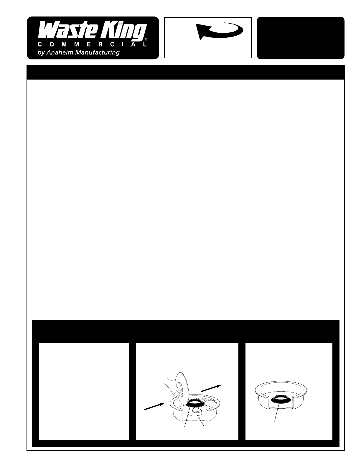
PROPER USE OF ALL PURPOSE ASSEMBLIES
For those who prefer a scrap block type
of operation.
Soiled Dishes
Silver Guard
Scrap Ring
Prerinse Dishes
Scrap Ring only
Minimum Silver Guard
protection.
NOTE:
Rotation of turntable viewed
from sink.
READ ALL INSTRUCTIONS CAREFULLY BEFORE OPERATING
INSTALLATION
INSTRUCTIONS
560P402P01 REV A
BEFORE INSTALLING, READ ENTIRE INSTRUCTIONS CAREFULLY
4240 E. La Palma Avenue, Anaheim, CA 92807 • (800) 454-4423
(PER U.L. 430)
FOR UNREINFORCED FLAT SURFACES:
CAST METAL: . . . . . . . . . . . . . . . . . . . . . . . . . . . . .NOT LESS THAN 1/8” (3.2 mm) THICK
MALLEABLE IRON: . . . . . . . . . . . . . . . . . . . . . . . . .NOT LESS THAN 3/32” (2.4 mm) THICK
DIE-CAST METAL: . . . . . . . . . . . . . . . . . . . . . . . . . .NOT LESS THAN 5/64” (2.0 mm) THICK
Metal of lesser thickness but not less than 3/32 inch (2.4mm), 1/16 inch (1.6mm) and 3/64 inch
(1.2mm) respectively, may be acceptable provided that the surface under consideration is: curved,
ribbed, or otherwise reinforced to provide mechanical strength or of a size or shape that provides
mechanical strength equivalent to that required.
Metal of lesser thickness may be acceptable when the following factors are taken into account:
A. MECHANICAL STRENGTH
B. RESISTANCE TO IMPACT
C. MOISTURE-ABSORPTION PROPERTIES
D. COMBUSTIBILITY
E. RESISTANCE TO CORROSION, AND
F. RESISTANCE TO DISTORTION AT TEMPERATURES TO WHICH THE
ENCLOSURE MAY BE SUBJECTED UNDER CONDITIONS OF
NORMAL OR ABNORMAL USE.
FOR A NON-METALLIC ENCLOSURE, ALL OF THESE FACTORS ARE TO BE
CONSIDERED WITH RESPECT TO THERMAL AGING.
SHEET METAL:
In addition to the above factors an enclosure of sheet metal shall be determined with respect to size
and shape, thickness of metal, and acceptability for the application, considering the intended use of the
disposer.
Generally, the use of sheet steel, having a thickness less than 0.0026 inch (0.66mm) if uncoated or
0.029 inch (0.74mm) if galvanized, or of nonferrous sheet metal having a thickness less than 0.036
inch (0.91mm) is not acceptable other than for the relatively small areas or for surfaces that are curved
or otherwise reinforced.
Sheet metal to which a wiring system is to be connected in the field shall have a thickness not less
than 0.032 inches (0.81mm) if uncoated steel, not less than 0.034 inches (0.86mm) if galvanized steel,
and not less than 0.045 inches (1.14mm) if nonferrous.
GUIDELINES FOR
FIELD CONSTRUCTED
ENCLOSURES

WITHIN THE U.S.A. AND CANADA OUTSIDE THE U.S.A. AND CANADA
WASTE KING COMMERCIAL
FOOD WASTE DISPOSERS
Models 500, 750, 1000, 1250, 1500, 2000, 3000, 5000, 10000
ONE YEAR WARRANTY
This appliance is warranted to be free of manufacturing defects in
workmanship and material for one full year beginning from the date of original
purchase. Any part found to be defective will be replaced free of charge.
Service labor is included. Parts wear is not considered a defect.
This warranty is for products purchased and retained in the 50 states of the
United States of America and Canada. This warranty is VOID if the appliance
is moved after the original installation. Should the appliance be sold by the
original purchaser during the warranty period, the new owner continues to be
protected with the appliance in the same location only, until the expiration
date of the original purchaser’s warranty period.
This warranty shall not apply if service is provided by anyone other than a
Factory Authorized Service Agency. Nor will the warranty apply to damage
resulting from accident, abuse, failure to follow operating instructions
,
alteration, or if the installation does not comply with our installation instructions
or local building codes.
HOW TO OBTAIN SERVICE
For service, contact the factory at 800-454-4423 for a referral to the nearest
factory authorized service agency.
We want you to remain a satisfied customer. If a problem does come up that
cannot be resolved to your satisfaction, please let us know. Write: National
Service Manager, at the address shown below or phone. Please be sure to
include the model number, serial number and date of original purchase.
WASTE KING COMMERCIAL
WARRANTY DEPARTMENT
4240 E. LA PALMA AVENUE
ANAHEIM, CALIFORNIA 92807
800-454-4423
www.wasteking.com
WASTE KING COMMERCIAL
FOOD WASTE DISPOSERS
Models 500, 750, 1000, 1250, 1500, 2000, 3000, 5000, 10000
ONE YEAR WARRANTY
This appliance is warranted to be free of manufacturing defects in
workmanship and material for one full year beginning from the date of original
purchase. Any part found to be defective will be replaced free of charge.
Labor is not included. Parts wear is not considered a defect.
This warranty shall not apply to damage resulting from accident, abuse,
failure to follow operating instructions
, alteration, or if the installation does not
comply with our installation instructions or local building codes.
This warranty is for products purchased and retained outside of the United
States of America, the District of Columbia and Canada.
HOW TO OBTAIN SERVICE
For warranty consideration, contact the dealer from whom you purchased the
appliance or write to us at the address shown below.
We want you to remain a satisfied customer. If a problem does come up that
cannot be resolved to your satisfaction, please let us know. Write: National
Service Manager, at the address shown below or phone. Please be sure to
include the model number, serial number and date of original purchase.
WASTE KING COMMERCIAL
WARRANTY DEPARTMENT
4240 E. LA PALMA AVENUE
ANAHEIM, CALIFORNIA 92807
U.S.A.
PHONE 01-01-714-524-7770
FAX 01-01-714-996-7073
www.wasteking.com
560P303P01
REV 12/97
