
Loading ...
Loading ...
Loading ...
7
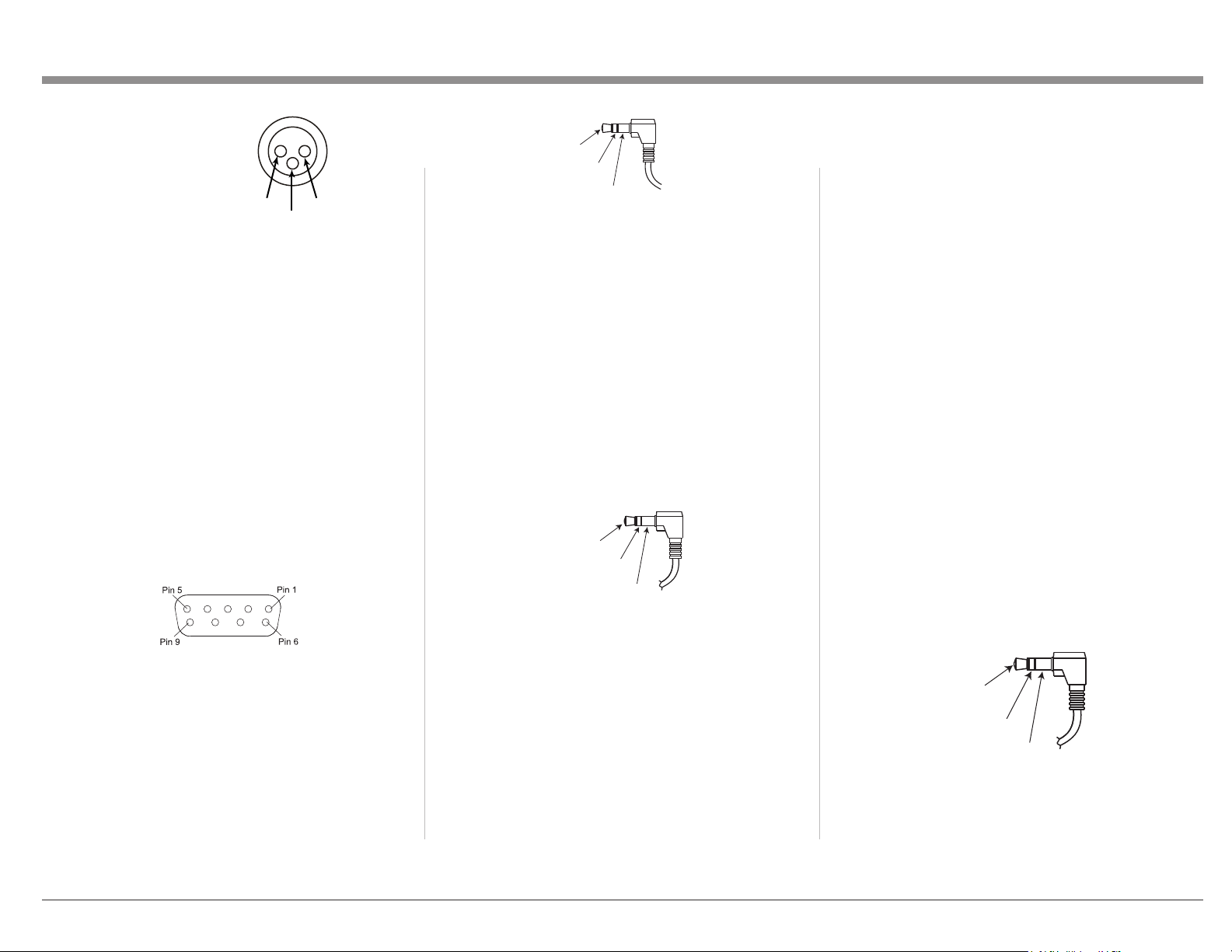
PIN 1: Shield/Ground
PIN 2: + Signal
PIN 3: - Signal
Unbalanced RCA/Phono Output
The Unbalanced Output (UNBAL L and R) allows
the MCD85 to be connected to an input, typically of
a preamplier, using RCA/ Phono cables. The top
white jack is left (L) and the lower red jack is right
(R).
RS232
The RS232 jack is used to connect the MCD85
to automation controller devices with RS232
connectors. To utilize this feature, you will need an
appropriate RS232 Data Cable. The RS232 Data
Cable should be an 1/8 inch (3.5mm) stereo mini
phone plug to a subminiature DB9 connector.
RS232 DB9 Connector Pin Layout
1. N/C (no connection) 6. N/C
2. Data In (RXD) 7. N/C
3. Data Out (TXD) 8. N/C
4. N/C 9. N/C
5. Gnd
Typical RS232 settings are:
• 8 data bits, no parity and one stop bit
• Baud rate xed at 115,200 bits per second
The baud rate can be changed in the Setup. See
“Baud Rate Setup” on page 11.
Wired IR Input
The IR Input allows an external IR receiver to be
attached to the MCD85. The Input is labeled IR IN.
By attaching an IR receiver using a 3.5mm cable
(see Figure 08), the MCD85’s Remote Control can
be used in another location without a line-of-sight to
the MCD85’s front IR sensor.
IR Data
Control
Ground
N/C
If using an external IR receiver for the MAIN
ZONE in the same room as the MCD85, you may
wish to disable the front IR sensor. This will avoid
potential timing issues of receiving the Remote
Control’s commands from two different Inputs.
The front IR can be turned on/off by doing the
following:
• Press and Hold the Left Knob for two seconds
• Turn the Left Knob to the menu choice
“SETUP: Front IR”
• Turn the Right Knob clockwise for Enabled
(on) or counterclockwise (off)
• Press and release the Left Knob to exit the
Setup menu
AC Power
This connection is essential. Plug the female end of
the supplied AC Power Cord into the AC connector
(standard 15 ampere IEC) located in the rear right
corner of the MCD85. Plug the male end of the AC
Power Cord into a grounded and functioning AC
outlet.
Power Control (Trigger) Output
The MCD85 has two Power Control jacks or
Triggers. One is an input (IN) and the other is an
output (OUT).
Power Control enables power on/off signals to go to
connected components so that other components can
automatically powered on (or off).
The controlling unit should be connected to the IN
jack. The MCD85 and units connected to the OUT
jack will follow the power status of the controlling
unit.
Connect components to the Triggers using a 3.5mm
stereo mini plug. See Figure 09. The Triggers work
by sending on/off signals in the form of +12 volt/0
volt to connected McIntosh components.
Power
Control
Meter
Illumination
Control
Ground
PIN 1
PIN 2
PIN 3
Figure 05– XLR pin diagram
Figure 06– Mini plug for RS232 connection
Data In
(DB9-pin2)
Ground
(DB9-pin5)
Data Out
(DB9-pin3)
Figure 07– DB9 connector pin layout
Figure 08– IR 3.5mm connector
Figure 09– Power control (trigger) mini plug
continued on page 9
Loading ...
Loading ...
Loading ...