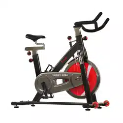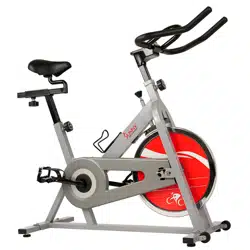
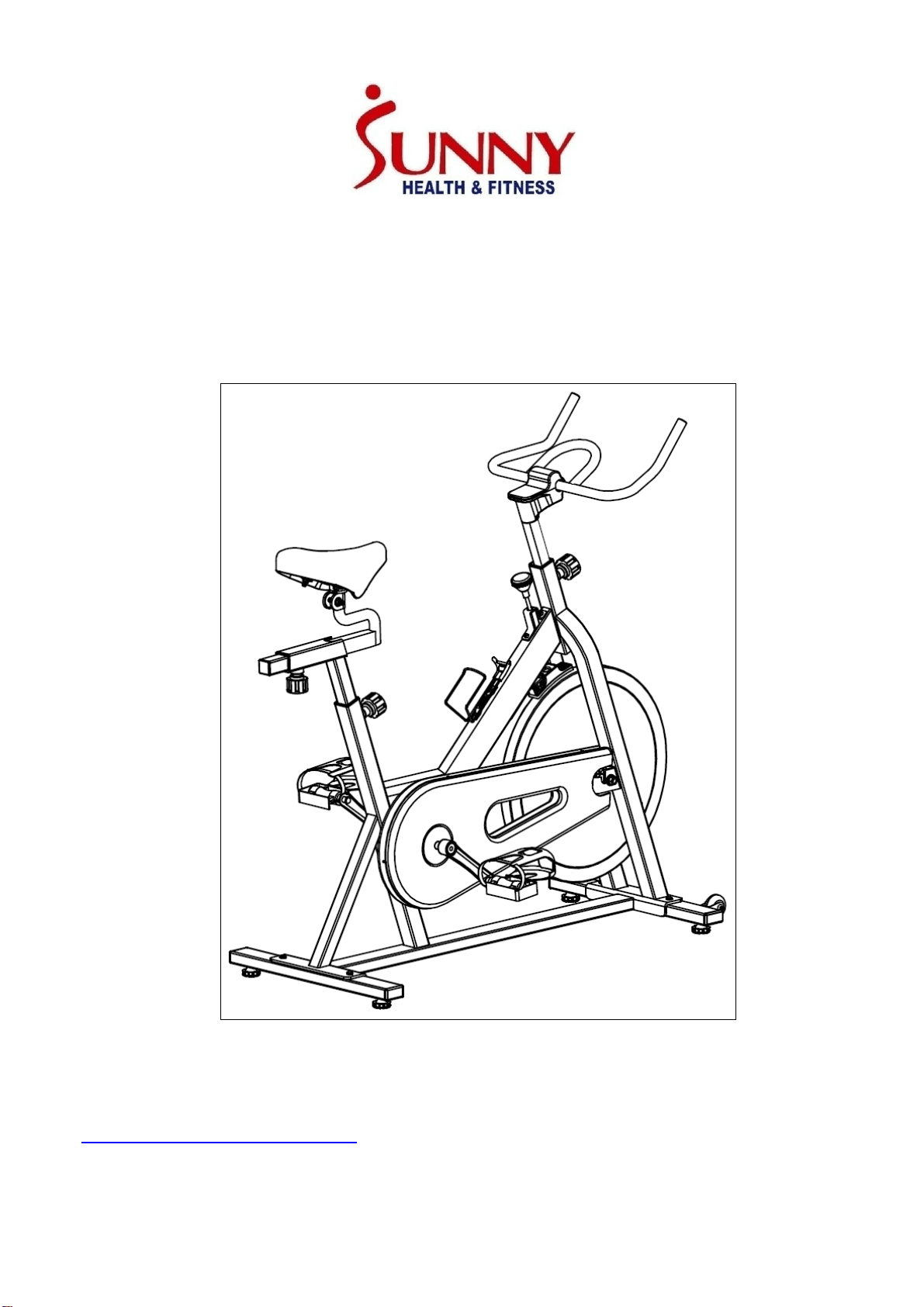
INDOOR CYCLING BIKE
SF-B1001
USER MANUAL
IMPORTANT! Please retain owner’s manual for maintenance and adjustment instructions. Your
satisfaction is very important to us, PLEASE DO NOT RETURN UNTIL YOU HAVE CONTACTED
US: [email protected] or 1- 877 - 90SUNNY (877-907-8669).

1
IMPORTANT SAFETY INFORMATION
We thank you for choosing our product. To ensure your safety and health, please use this equipment
correctly. It is important to read this entire manual before assembling and using the equipment. Safe
and effective use can only be achieved if the equipment is assembled, maintained and used properly.
It is your responsibility to ensure that all users of the equipment are informed of all warnings and
precautions.
1. Before starting any exercise program, you should consult your physician to determine if you have
any medical or physical conditions that could put your health and safety at risk or prevent you
from using the equipment properly. Your physician’s advice is essential if you are taking
medication that affects your heart rate, blood pressure or cholesterol level.
2. Be aware of your body’s signals. Incorrect or excessive exercise can damage your health. Stop
exercising if you experience any of the following symptoms: pain, tightness in your chest,
irregular heartbeat, shortness of breath, lightheadedness, dizziness or feelings of nausea. If you
do experience any of these conditions, you should consult your physician before continuing with
your exercise program.
3. Keep children and pets away from the equipment. The equipment is designed for adult use only.
4. Use the equipment on a solid, flat level surface with a protective cover for your floor or carpet. To
ensure safety, the equipment should have at least 4 feet (1.2 M) of free space all around it.
5. Ensure that all nuts and bolts are securely tightened before using the equipment. The safety of
the equipment can only be maintained if it is regularly examined for damage and/or wear and tear.
6. Always use the equipment as indicated. If you find any defective components while assembling
or checking the equipment, or if you hear any unusual noises coming from the equipment during
exercise, discontinue use of the equipment immediately and do not use until the problem has
been rectified.
7. Wear suitable clothing while using the equipment. Avoid wearing loose clothing that may become
entangled in the equipment.
8. Do not place fingers or objects into the moving parts of the equipment.
9. The maximum weight capacity of this unit is 220 pounds (100 KG).
10. The equipment is not suitable for therapeutic use.
11. To avoid bodily injury and/or damage to the product or property, proper lifting and moving is
required.
12. Your product is intended for use in cool, dry conditions. You should avoid storage in extreme cold,
hot or damp areas as this may lead to corrosion and other related problems.
13. This equipment is designed for indoor and home use only, it is not intended for commercial use!

2
EXPLODED DIAGRAM

3
PARTS LIST
No.
Description
Spec.
Qty.
No.
Description
Spec.
Qty.
1
Main Frame
1
33
Protective Cover
1
2
Front Stabilizer
1
34
Brake Knob
1
3
Rear Stabilizer
1
35
Hex Nut
M8
2
4
Handlebar
1
36
Hex Nut
1
5
Seat Post
1
37
Spacer
Φ12XΦ9X15
1
6
Seat Slider
1
38
Square Nut
M8
1
7
Seat
1
39
Spring
1
8
Pop-Pin Knob
3
40
Mat Cover
1
9L/R
Pedal
1 pr.
41
Block
1
10L/R
Crank
1 pr.
42
Hex Nut
M6
1
11
Foot Leveler
4
43
Nylon Nut
M6
1
12
Square Cap
4
44
Phillips Tapping
Screw
M5X15
2
13
Flat Washer
Φ8X1.5XΦ16
10
45
Spring Clamp
1
14
Allen Bolt
M8X20XΦ15
4
46
Rubber Pad
2
15
Plastic Bushing
3
47
Nylon Nut
M5
2
16
Square Cap
1
48
Flat Washer
D5
4
17
Phillips Tapping
Screw
M5XL12
2
49
Fixed Bracket
1
18
Hex Nut
M10
4
50
Conical Spring
1
19
Water Bottle
Holder
1
51
Brake Block
1
20
Nylon Nut
M8
2
52
Wool Felt
1
21
Foam Grip
2
53
Phillips Screw
M5X30
2
22
Cap
2
54
Chain
1
23
Allen Bolt
M8X16XΦ15
4
55
Phillips Tapping
Screw
M8X45
2
24
Spring Washer
D8
4
56
Cap Nut
M12
2
25
A/B
Handlebar Cover
1 pr.
57
Flat Washer
Φ25XΦ13X2
2
26
Handlebar Post
1
58
Hex Thin Nut
M12X1
2
27
Phillips Screw
ST4X8
4
59
Spacer
Φ18XΦ12.2X9
2
28
Allen Bolt
M8X40XL12
2
60
Conical Thin Nut
M12X1
2
29
Roller
2
61
Bearing
2
30L/R
Chain Cover
1pr.
62
Flywheel
1
31
Chain Plate
1
63
Flywheel Axle
1
32
Center Axle
1
64
Wheel Inner
Sleeve
1
4
65
Small Chain
Wheel
1
74
Stop Washer
1
66
Nut
2
75
Two-Slot Nut
1
67
Flat Washer
Φ5.5X1.0XΦ1
2
2
76
Ball Bearing
2
68
Cross Pan Head
Tapping Screw
ST4.2X25
2
77
Centre Bowl
2
69
Cross Pan Head
Tapping screw
ST5X10
5
78
Three Slot Nut
1
70
Flat Washer
Φ5.5X0.5XΦ1
0
5
79
Big Flat Washer
1
71
Long Spacer
Φ16XΦ12X41
1
80
Allen Wrench
S6
1
72
Crank Cover
2
81
Spanner
S10,13, 14,
15,17
1
73
Flange Nut
M10X1.25
2
Ordering Replacement Parts (U.S. and Canadian Customers only)
Please provide the following information in order for us to accurately identify the part(s) needed:
The model number (found on cover of manual)
The product name (found on cover of manual)
The part number found on the “EXPLODED DIAGRAM” and “PARTS LIST” (found near the
front of the manual)
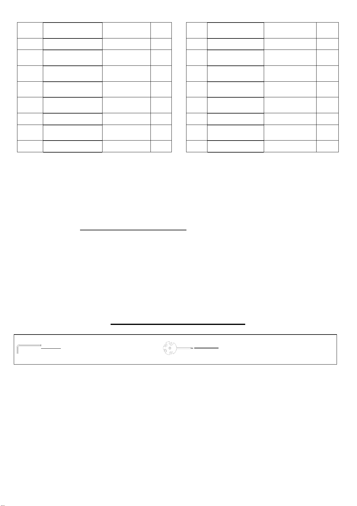
HARDWARE PACKAGE
#
# 80 Allen Wrench S6 1PC
#
# 81 Spanner S10, 13, 14, 15,17 1PC
5
ASSEMBLY INSTRUCTIONS
We value your experience using Sunny Health and Fitness products. For assistance with parts or
troubleshooting, please contact us at suppo[email protected] or 1-877-90SUNNY (877-
907-8669).
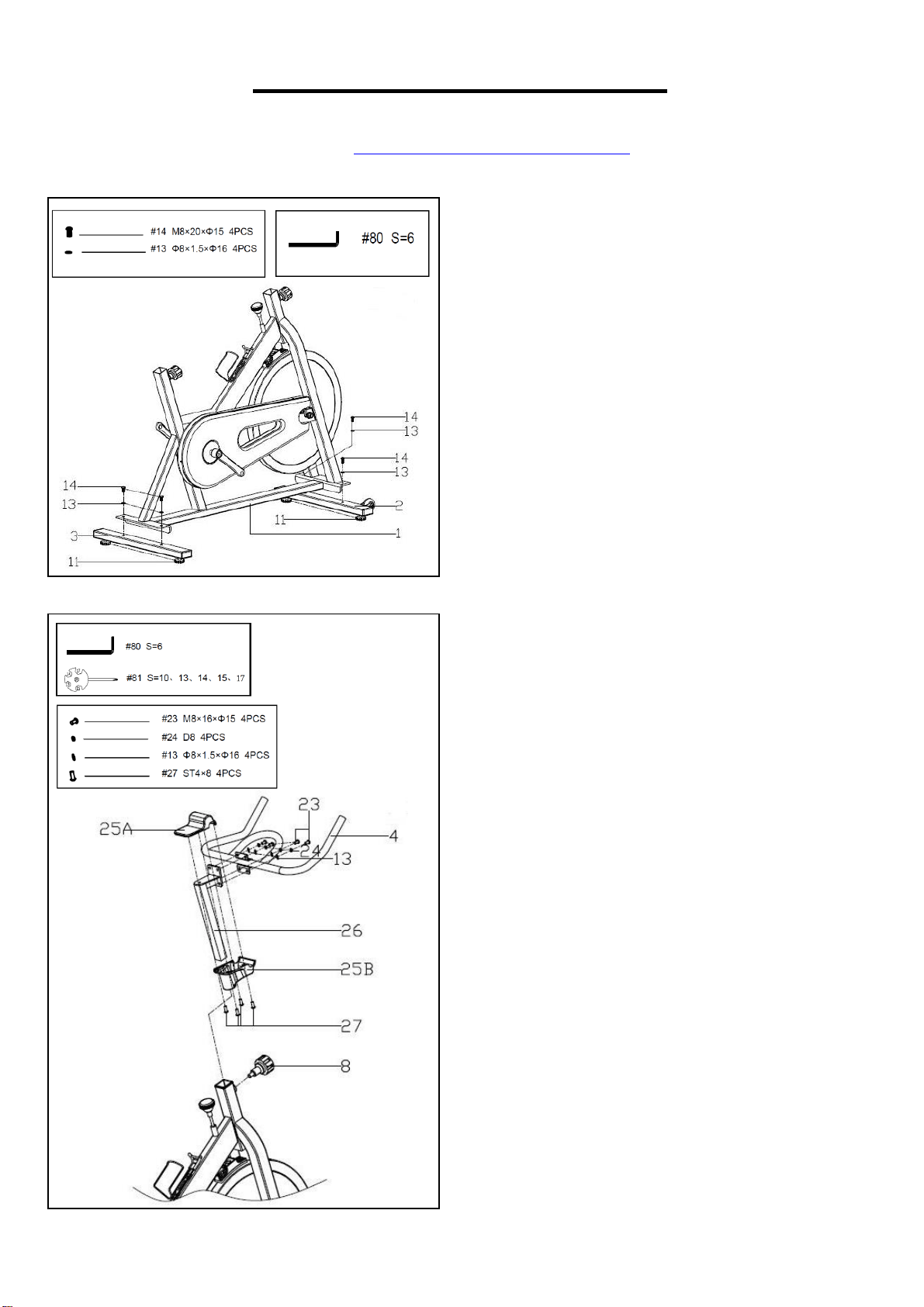
STEP 1:
Remove the preassembled 4 Allen Bolts (No.
14) and 4 Flat Washers (No. 13) from the
Front Stabilizer (No. 2) and Rear Stabilizer
(No. 3).
Attach the Front Stabilizer (No. 2) and Rear
Stabilizer (No. 3) to the Main Frame (No. 1)
with 4 Allen Bolts (No. 14) and 4 Flat
Washers (No. 13). Tighten and secure with
Allen Wrench (No. 80). Make sure the Foot
Levelers (No. 11) are on the bottom and the
transportation wheels facing up at the front of
the bike.
STEP 2:
Remove the preassembled 4 Allen Bolts (No.
23), 4 Flat Washers (No. 13) and 4 Spring
Washers (No. 24) from Handlebar Post (No.
26). Attach the Handlebar (No. 4) to the
Handlebar Post (No. 26) using 4 Allen Bolts
(No. 23), 4 Flat Washers (No. 13) and 4
Spring Washers (No. 24). Tighten and secure
with Allen Wrench (No. 80).
Remove the preassembled 4 Phillips Screws
(No. 27) from Top Cover (No. 25A). Insert
Handlebar Post (No. 26) through Lower
Handlebar Cover (No. 25B). Slide the Lower
Handlebar Cover (No. 25B) to the top of the
Handlebar Post (No. 26).
Use 4 Phillips Screws (No. 27) to attach the
Top Cover (No. 25A) to the Lower Handlebar
Cover (No. 25B) so the Handlebar (No. 4) and
Handlebar Post (No. 26) are in between the
Handlebar Covers (No. 25A & No. 25B).
Loosen Pop-Pin Knob (No. 8), pull the pin, and
then insert the handlebar assembly into the
Main Frame (No. 1). Make sure the pin settles
into the desired hole and secure the Pop-Pin
Knob (No. 8).
6
We value your experience using Sunny Health and Fitness products. For assistance with parts or
troubleshooting, please contact us at suppo[email protected] or 1-877-90SUNNY (877-
907-8669).
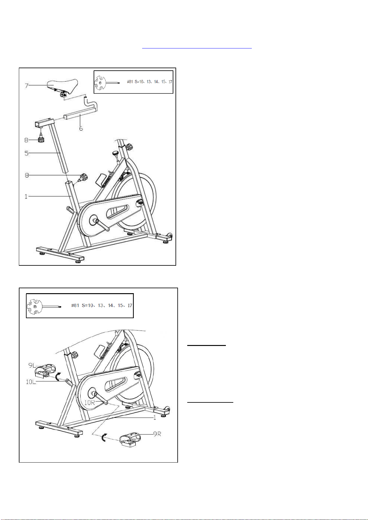
STEP 3:
Lock the
Seat (No. 7)
onto the
Seat Slider
(No. 6)
tightly
. Tighten and secure with
Spanner (No. 81).
Adjust the seat to the
desired position by sliding it on
Seat Slider
(No. 6)
then lock the
Seat Slider (No. 6)
on
the
Seat Post (No. 5)
with
Pop-Pin Knob
(No. 8)
. Insert the
Seat Post (No. 5)
to the
rear upright tube of
Main Frame (No. 1)
then
adjust the height and secure with
Pop-Pin
Knob (No. 8).
Note:
Both the fore/aft and up/down
adjustments of the
Seat (No. 7)
need to be
secured with
Pop-Pin Knob (No. 8)
. Ensure
the
Seat (No. 7)
is locked onto the
Seat
Slider (No. 6)
before adjusting the height.
STEP 4:
Attach the Pedal (No. 9L/R) to their
corresponding Crank (No. 10 L/R). Before you
begin, immobilize the crank arms by turning the
brake knob all way to the right.
Left Pedal: The Left Pedal (No. 9L) is marked
L for left side. Align the Left Pedal (No. 9L) to
the Left Crank (No. 10L) at 90 degrees and
insert the pedal. Turn counter-clockwise as
tightly as you can with your hand then secure
with Spanner (No. 81).
Right Pedal: The Right Pedal (No. 9R) is
marked R for right side. Align the Right Pedal
(No. 9R) to the Right Crank (No. 10R) at 90
degrees and insert the pedal. Turn clockwise
as tightly as you can with your hand then
secure with Spanner (No. 81).
Assembly is complete!
7
ADJUSTMENTS & USAGE GUIDE
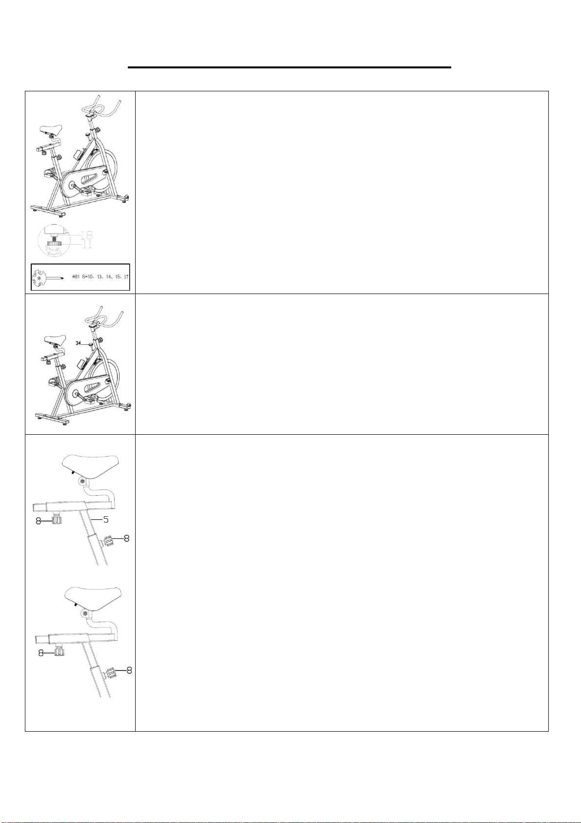
ADJUSTING THE BALANCE
In order to achieve a smooth and comfortable ride, you must ensure that
the stability of the bike is secured. If you notice that the bike is unbalanced
during use, you should adjust the foot levelers located beneath the front
and rear stabilizers. To do so, use Spanner (No. 81) to loosen Hex Nut
(No. 18) by turning it clockwise (direction A). With the nut loosened, rotate
Foot Levelers (No. 11) until it sits level with the surface that the bike is
on. When you have finished adjusting the foot leveler, use Spanner (No.
81) to re-tighten the Hex Nut (No. 18) by turning it counter-clockwise
(direction B). If required, repeat this process to adjust the remaining feet.
ADJUSTING THE TENSION & EMERGENCY STOP
Adjust the resistance of the bike using the Brake Knob (No. 34). Increase
the level of resistance by turning the tension knob to the RIGHT
(clockwise), decrease the level of resistance by turning the tension knob to
the LEFT (counter-clockwise). Push down on the Brake Knob (No. 34) for
emergency brake.
ADJUSTING THE SEAT
An appropriate seat height helps to ensure your exercise efficiency and
reduce the risk of injury. Adjusting the seat forward or backward can help
you work out different body muscle groups.
With one pedal in the upward position, place your foot in the toe clip and
get on the bike. If your leg is bent too much, you should move the seat
up. If your foot cannot touch the pedal or your leg is too straight, you
should move the seat down. Dismount the bike.
Loosen the [seat adjustment] Pop-Pin Knob (No. 8) to raise or lower Seat
Post (No. 5) to the desired position. Make sure Pop-Pin Knob (No. 8)
secures into the desired hole.
Loosen Pop-Pin Knob (No. 8) to move the seat forward or backward to
the desired position. Once the position is located, firmly secure Pop-Pin
Knob (No. 8) by turning clockwise.
8
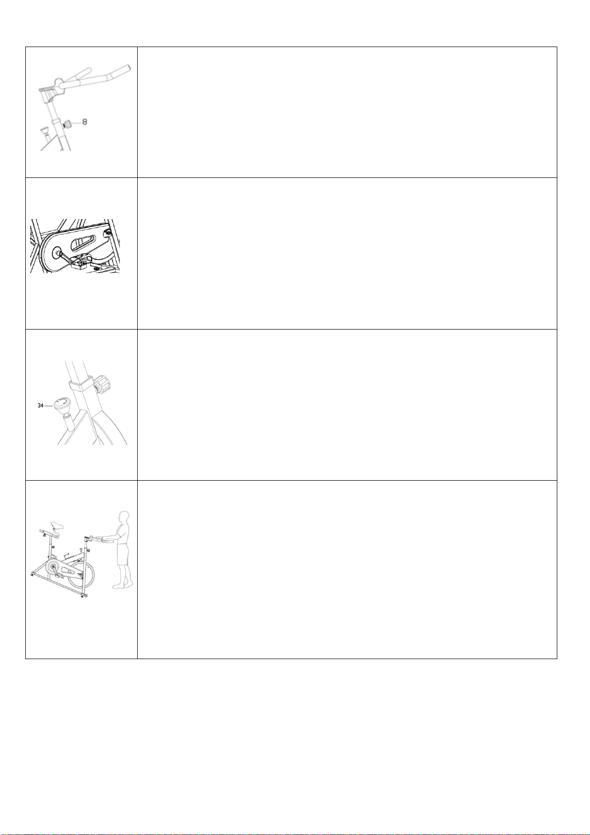
DISMOUNTING THE BIKE
Stop the flywheel at any time by pushing down on Brake Knob (No. 34).
When the pedals have stopped moving, loosen the pedal straps. Then you
can dismount the bike.
WARNING! Do not dismount the bike or remove your feet from the pedals
until the pedals have stopped completely.
ADJUSTING THE HANDLEBAR
Loosen the [handlebar adjustment] Pop-Pin Knob (No. 8) to raise or lower
the handlebar to the desired position. Make sure the Pop-Pin Knob (No.
8) settles into the desired hole and secure it firmly by turning clockwise.
ADJUSTING THE PEDAL STRAP
Place the ball of each foot in the toe clips so the front of your shoe fits
snugly in the toe clip cage. Rotate one foot to within arm’s reach and pull
the strap until the top clip cage fits your shoe snugly. Insert the strap back
into the hoop of the toe clip. Repeat this for the other foot.
MOVING THE BIKE
To move the bike, first ensure that the handlebar is properly secured. If the
handlebar is loose, tighten the Knob to secure it. Next, stand at the front of
the bike so that you’re directly in front of the handlebar. Firmly grasp and
hold each side of the handlebar, place one foot on the front stabilizer and
tilt the bike towards you until the transportation wheels on the front
stabilizer touch the ground. With the wheels on the ground, you can
transport the bike to the desired location with ease.

9
MAINTENANCE INSTRUCTIONS
This is general information for daily, weekly and monthly maintenance to be performed on your bike.
Version 1.5
DAILY MAINTENANCE
After each exercise session, wipe down all
the equipment: seat, frame, handlebars. Pay
special attention to the seat post, handlebar
post and belt/chain guard. Sweat is very
corrosive and may cause problems that
require parts replacement later.
1. Get on the bike and engage the drive
train.
2. Pay attention to any vibrations felt
through the pedals. If you feel any
vibrations, you may need to tighten the
pedals, bottom bracket, or adjust the drive
belt/chain tension.
3. Use a wrench to tighten the pedals until
they are secure.
MONTHLY MAINTENANCE
1. Check all hardware is secure, such as: water
bottle holder, flywheel nuts, belt/chain guard
bolts, brake caliper lock nuts and brake
caliper tension rod nuts.
2. Inspect the brake tension rod for signs of
wear such as missing threads. Clean and
lubricate the brake tension rod.
3. Clean and lubricate the seat post, handlebar
post and seat slider. Remove any build up of
foreign material.
WEEKLY MAINTENANCE
1. Inspect moving parts and tighten the
hardware.
2. Inspect pull pin frame fittings, making
sure the fittings are snug. Loose frame
fittings may strip out threads over time
and cause extensive damage.
3. Clean and lubricate pop pin assemblies.
Pull on the pin and spray a small amount
of lubricant onto the shaft.
4. Tighten the seat hardware, making sure
the seat is level and centered.
5. Brush and treat the resistance pads.
Remove any foreign material that may
have collected on the pads. Spray the
pads with silicone lubricant. This helps to
reduce noise from friction between the
pads and the flywheel.
6. Visually inspect the bottom bracket, toe
clips and toe straps. If any of them are
loose or disconnected, attach and tighten.
LEATHER BRAKE PAD CARE (If Applicable)
1. Perform this maintenance when the brake
pad is first installed and for the life of the
brake pad. Following these simple guidelines
can increase the life of your brake pads.
2. Some brake pad assemblies are pre-
lubricated. Squeeze the brake pad. If
lubricant is released, then the pad has been
pre-lubricated.
3. If the brake pad is dry, then coat the brake
pad with 3-n-1 oil. Brush the leather with a
clean, wire bristle brush, and then apply the
oil. The oil should be allowed to soak in to
the pad. Repeat 4-5 times until the pad is
saturated, but not dripping with oil. When the
pad is saturated, it will no longer absorb oil.
4. Inspect the brake pad weekly and lubricate if
needed. The pad should not have a glazed
appearance. If the pad appears glazed, then
brush it with wire brush and apply lubricant
as needed. If any of the sponge padding is
showing through the leather pad, the brake
pad should be replaced.