04306281/5 - 414-98
INSTRUCTIONS POUR L'EMPLOI
INSTRUCTIONS FOR USE
GEBRAUCHSANWEISUNG
ISTRUZIONI PER L'USO
GEBRUIKSAANWIJZING
13
15
14
sovr.04306682
CBT62 - CBT92
WARNING
--------------------------------------------------------
The distance between the hob and the lower
part of the hood must be at least 65 cm.
The air collected must not be conveyed
into a duct used to blow off smokes from
appliances fed with an energy other than
electricity (central heating systems, ther-
mosiphons, water-heaters, etc.).
Comply with the official instructions provided
by the competent authorities in merit when
installing the disposal duct. In addition,
exhaust air should not be discharged into
a wall cavity, unless the cavity is designed
for that purpose.
The room must be well aerated in case a
hood and some other heat equipment fed
with an energy other than electricity (gas,
oil, coal heaters, etc) operate at the same
time. In fact the intake hood, disposing of
air, could create a vacuum in the room.
The vacuum should not exceed 0,04mbar.
This prevents the gas exhausted by the
heat source from being intaken again. It is
therefore advisable to ensure the room
contains air taps able to ensure a steady
flow of fresh air.
Check the data label inside the
appliance; if the symbol ( ) is printed,
read the following: this appliance has
such technical particulars that it
belongs to class II insulation, therefore
it must not be earthed.
The following warning is valid in the United
Kingdom only: as the colours of the wires
in the mains lead of this appliance may not
correspond with the coloured markings
identifying the terminals in your plug,
proceed as follows:
– the wire which is coloured blue must be
connected to the terminal which is marked
with the letter N or coloured black;
– the wire which is coloured brown must
be connected to the terminal which is
marked with the letter L or coloured red.
– terminal of a three-pin plug.
Check the data label inside the applian-
ce; if the symbol ( ) is NOT printed,
read the following: ATTENTION: This
English
appliance must be grounded. When
making the electrical connections, check that
the current socket has a ground connection.
The following warning is valid in the United
Kingdom only: as the colours of the wires
in the mains lead of this appliance may not
correspond with the coloured markings
identifying the terminals in your plug,
proceed as follows:
– the wire which is coloured green and
yellow must be connected to the terminal
in the plug which is marked with the letter
E or by the earth symbol [ ], or coloured
green or green and yellow;
– the wire which is coloured blue must
be connected to the terminal which is
marked with the letter N or coloured black;
– the wire which is coloured brown must
be connected to the terminal which is
marked with the letter L or coloured red.
When making the electrical connections,
check that the voltage values correspond
to those indicated on the data plate inside
the appliance itself.
In case your appliance is not furnished with
a non separating flexible cable and has no
plug, or has not got any other device ensu-
ring omnipolar disconnection from the elec-
tricity main, with a contact opening distance
of at least 3 mm, such separating device
ensuring disconnection from the main must
be included in the fixed installation.
Always switch off the electricity supply before
carrying out any cleaning or servicing
operations on the appliance.
USE
--------------------------------------------------------
Avoid using materials which could cause
spurts of flame (flambées) near the ap-
pliance.
When frying, take particular care to prevent
oil and grease from catching fire. Already
used oil is especially dangerous in this re-
spect. Do not use uncovered electric grates.
To avoid possible risks of fire always comply
with the indicated instructions when cleaning
anti-grease filters and when removing
grease deposits from the appliance.
MAINTENANCE
--------------------------------------------------------
Thorough servicing guarantees correct and
long-lasting operation.
Particular care must be paid to the anti-
grease filters which must be periodically
cleaned in relation to use (at least once
every two months). Remove the anti-
grease filters and wash them either by
hand or in the dishwasher using neutral
detergent. To take off the anti-grease filters:
at the handle, push the stop inwards and
pull the filter downwards (Fig.3); open the
trolley and take off the other filter doing the
same.
Any fat deposits should be removed from
the appliance periodically depending on
amount of use (at least every 2 months).
Avoid using abrasive or corrosive products.
To clean painted appliances on the outside,
use a cloth dipped in lukewarm water and
neutral detergent. To clean steel, copper
or brass appliances on the outside, it is
always best to use specific products,
following the instructions on the products
themselves. To clean the inside of the
appliance, use a cloth (or brush) dipped in
denatured ethyl alcohol.
DESCRIPTION
--------------------------------------------------------
The appliance can be a filtering version one,
a ducting version one or with an external
motor.
In the Filtering version (Fig. 1), the air and
vapours conveyed by the appliance are depu-
rated by charcoal filter and recirculated around
the room. ATTENTION: Using the hood as a
filtering one it is necessary to use the char-
coal filter that purifies the air sent back into
the room.
In the Ducting version (Fig. 2), cooking va-
pours and odours are conveyed straight out-
side by a disposal duct which passes through
the wall/ceiling. Use of charcoal filter is there-
fore unnecessary.
In the version with an External motor (Fig.
3), the appliance must be connected to an
ducting apparatus/motor which works on its
own using the appliance as a union for the air
to be scavenged. Use only motors pro-
posed in the original catalogue.
According to the model you have bought, the
appliance can include 1 or 2 motors. In the I
motor version the flange for the air to be
exhausted has not got a central position, but
it is slightly on the left.
INSTALLATION
--------------------------------------------------------
Before assembling, in order to manoeuvre the
appliance more easily, take off the anti-grease
filters: at the handle, push the stop inwards
and pull the filter downwards (Fig. 4); open the
trolley and take off the other filter doing the
same.
IMPORTANT: So as not to damage your
product, during installation USE ONLY THE
SCREWS PROVIDED. Make sure these are
used as shown in the following
instructions.
To compensate possible depth voids be-
tween the appliance and the wall, a plastic
SPACING BAR to be fixed at the back of
the appliance by means of the three
screws A is included (Fig. 5). The 3 screws
A to be used are contained in the acces-
sory bag attached to the plastic spacing
bar. Cut the spacing bar according to the
distance to be adjusted.
Assembly under a pensile cupboard
The following operations are essential for
assembly:
– Install the wiring system
– Prepare the air venting hole if your
appliance is to be installed in the ducting
version or in the version with an external
motor.
In the Ducting version and in the version with
an External motor, to get optimal conditions
the air venting pipe should:
– be as short as possible.
– have the lowest number of bends (max
bende angle: 90°).
– be made of material approved by local
authorities (according to the State).
– have its inner side as regular and smooth
as possible.
It is moreover recommended to avoid drastic
changes of pipe cross section (recommended
diameter: 125 mm).
Fixation as indicated in Fig. 6:
Using the relative template make the 4
necessary fixing holes in the bottom of
the cupboard and cut the air venting hole.
For the version with an External motor,
make the electrical connection between
the hood and the external motor by means
of the proper terminal board (Fig. 8): take
off the cable clamp A and the cover B of
the wiring junction box. Fix the connec-
tion cable of the motor onto the terminal
board C. Reassemble the cable clamp A
and the cover B of the junction box. The
other end of the cable must be fixed onto
the terminal board of the external motor.
Move the hood close to the bottom of the
wall unit and then connect the two units
by means of the 4 self-tapping screws
supplied together with the appliance.
Fixation with brackets as in Fig. 7 (optio-
nal):
Take the two brackets (S) out of the
accessory bag together with the 8 screws
provided. Fit the brackets to the wall unit
being careful to position these correctly;
for this operation use the 4 longer screws.
At this point, secure the appliance to the
brackets using the 4 shorter screws.
Ducting version and version with an External
motor: connect the flange of the hood with the
air venting hole made previously in the wall/
ceiling by means of an adequate tube. Make
the electrical connection of the hood by means
of the power supply cable. Reassemble the
anti-grease filters.
Filtering version: connect a proper pipe to the
flange of the hood so that the air is sent
outside the pensile and sent back into the
room. Make the electrical connection of the
hood by means of the power supply cable.
Assemble the charcoal filter minding that it
restains properly against edge A (Fig. 12).
Reassemble the anti-grease filters.
OPERATION
--------------------------------------------------------
Controls of Fig. 9:
Switch C: position A (automatic), the motor
and the light are automatically regulated
ON or OFF by the opening/closing of the
truck. Position M (manual), the light is on.
Position 0, the light is off.
Switch B: it select the speed of the motor.
Opening the truck, the motor works automati-
cally at the last working speed.
Controls of Fig. 10:
Switch C: position M (motor): the motor
switches ON/OFF by opening/closing the
truck; the lights are always OFF.
Position T (total): the motor and the lights
switch ON/OFF by opening/closing the
truck.
Position L: the lights switch ON and the
motor switch OFF either if the truck is
open or closed; the motor is always OFF.
Switch B: it select the speed of the motor.
When the switch is in M or T position, opening
the truck, the motor starts working automati-
cally at the selected speed.
Controls of Fig. 11:
Switch D: position A (automatic), the motor
and the light are automatically regulated
ON or OFF by the opening/closing of the
truck. Position M (manual), the light is on.
Position 0, the light is off.
Opening slightly the truck, the motor works at
the I speed; opening a bit more, the motor
works at the II speed; opening totally the
truck, the motor works at the III speed.
In case the hood is a filtering version one, it
is necessary to change the charcoal filters
according to utilization about every six month.
To remove the charcoal filter:
– open the truck pulling it frontwards.
– take off the anti-grease filter: where the
handle is, pull the stop inwards and pull
the filter downwards (Fig. 4);
– grasp the tongue of the charcoal filter
pulling it towards the rear of the apparatus
and, at the same time, downwards (Fig.
12-13). Attention: to take off the charcoal
filter, this one must restain properly against
edge A (Fig. 12).
Light bulb
If the fluorescent light need changing,
slacken the light cover by disconnecting the
screw and remove the bulb itself (Fig. 14).
Replace with a bulb of the same type.
To change the rectangular halogen bulbs
open the cover and remove the bulb without
touching it with bare hands (Fig.15). Replace
with a bulb of the same type.
MONTAGE UND
GEBRAUCHSANWEISUNG
--------------------------------------------------------
Das Gerät ist so zu montieren, daß der
Abstand zwischen den Kochplatten und
dem unteren Rand der Dunstabzugshaube
mindestens 65 cm beträgt.
Ein Anschluss der Abluftleitungen an
Verbrennungsabgaskamine (zum Beispiel
Zentralheizung, Heizgeräte, Badezimmer-
öfen usw.) ist nicht gestattet.
In jedem Fall sind bei der Ableitung der
Abluft die behö rdlichen Vorschriften zu
beachten. Desweiteren darf die Abluft nur
dann durch ein Loch in der Wand geleitet
werden, wenn dieses fü r diesen Zweck
bestimmt ist.
Achtung! Bei gleichzeitigem Betrieb einer
Abluft-Dunstabzugshaube und einer ra-
umluftabhä ngigen Feuerstä tte (wie z. B.
gas-, öl- oder kohlebetriebene Heizgeräte,
Durchlauferhitzer, Warmwasserbereiter) ist
Vorsicht geboten, da beim Absaugen der
Luft durch die Dunstabzugshaube dem
Aufstellraum die Luft entnommen wird, die
die Feuerstä tte zur Verbrennung benötigt.
Ein gefahrloser Betrieb ist mö glich, wenn
bei gleichzeitigem Betrieb von Haube und
raumluftabhä ngiger Feuerstä tte im Aufstell-
raum der Feuerstätte ein Unterdruck von
hö chstens 0,04 mbar erreicht wird und
damit ein Rü cksaugen der Feuerstätten-
abgase vermieden wird. Daher den Raum
mit Lü ftungsanschlü ssen versehen, die
einen konstanten Zustrom von Frischluft
gewä hrleisten.
Das Typenschild im Innern des Gerä ts
kontrollieren: Den folgenden Anwei-
sungen folgen, falls das Symbol ( )
erscheint; dieses Gerä t weist kons-
truktive technische Details auf, die
unter die Isolierungsklasse II fallen und
deshalb muss es nicht geerdet werden.
Das Typenschild im Innern des Gerä ts
kontrollieren: den folgenden Anwei-
sungen folgen, falls das Symbol ( )
erscheint; ACHTUNG: dieses Gerä t
muss geerdet werden. Beim elektrischen
Anschluss sicherstellen, dass die Steckdose
Deutsch
eine Erdung aufweist.
Beim elektrischen Anschluss muss ü berprü ft
werden, ob die Spannungswerte des
Stromnetzes mit den Werten auf dem im
Innern des Gerä tes angebrachten Typens-
childs übereinstimmen. Falls Ihr Gerä t nicht
mit einem fest angeschlossenem Kabel mit
Stecker oder einer sonstigen Vorrichtung,
die eine allpolige Unterbrechung mit einer
Kontaktö ffnung von mindestens 3 mm
versehen ist, so mü ssen die entsprechen-
den Trennvorrichtungen bei der festen
Installation vorgesehen werden
Vor jeder Reinigungs- oder Wartungsarbeit
muss das Gerät vom Stromnetz getrennt
werden.
GEBRAUCH
--------------------------------------------------------
In der unmittelbaren Nä he des Gerä ts die
Benutzung von flammenerzeugenden
Materialien (Flambieren) vermeiden.
Beim Frittieren besonders auf die Brand-
gefahr achten, die durch Ö l und Fette
verursacht wird. Besonders gefä hrlich ist
die Entflammbarkeit von bereits benutztem
Ö l. Keine offenen Elektrogrills verwenden.
Zur Vermeidung einer mö glichen Brandge-
fahr die Anweisungen zur Reinigung der
Fettfilter und zur Entfernung eventueller
Fettablagerungen auf dem Gerä t beachten.
WARTUNG
--------------------------------------------------------
Nur eine sorgfä ltige Pflege garantiert auf
Dauer eine gute Leistung und Funktion
des Gerä ts.
Besonders wichtig ist die Reinigung der
Fettfilter. Hierzu sind die Metallfilter
abzunehmen. Die Reinigung wird von Hand,
mit biologisch abbaubarem
Reinigungsmittel, oder in der Spülmaschine
empfohlen. Die Reinigungshäufigkeit hängt
ab von der Benutzungsdauer und der Art
der abzusaugenden Wrasen. Zum
Enfgernen der Entfettungsfilter: in
Überreinstimmung mit dem Handgriff den
Feststeller nach innen stossen und den
Filter nach unten ziehen (Abb. 3);
Schiebegestell ö ffnen und den zweiten Filter
auf die gleiche Weise herausnehmen.
Die Entfernung eventueller
Fettablagerungen vom Gerä t erfolgt in
regelmä ßigen Abstä nden in Abhä ngigkeit

von der Benutzung (zumindest alle zwei
Monate). Die Verwendung von
scheuernden oder korrosiven Produkten
vermeiden. Für die äußere Reinigung von
lackierten Gerä ten ein mit lauwarmen
Wasser und Neutralreiniger angefeuchtetes
Tuch verwenden; für die äußere Reinigung
der Gerä te aus Stahl, Kupfer und Messing
wird die Verwendung von Spezialprodukten
empfohlen, wobei die auf dem Produkte
angegebenen Anweisungen zu beachten
sind; für die innere Reinigung der Gerä te
einen in denaturalisierten Ä thylalkohol
eingetauchten Lappen (oder Pinsel)
verwenden.
GERÄ TEAUSFÜ HRUNG
--------------------------------------------------------
Das Gerät wird in einer Ausführung geliefert, die
einen Einsatz sowohl im Umluftbetrieb als auch
im Abluftbetrieb zulä ßt.
Bei Umluftversion (Abb. 1) werden die durch
das Gerät beförderten Dü nste und die Abluft
durch die Aktivkohlefilter gereinigt und wieder in
den Raum zurü ckgefü hrt. ACHTUNG: Bei
Umluftversion sind Aktivkohlefilter zu verwenden,
die die in den Raum zurückgeführte Luft reinigen.
Bei Abluftversion (Abb. 2) werden Dampf und
Kü chengerüche direkt, mit einem durch Wand
oder Zimmerdecke gefü hrten Abluftkanal, ins
Freie geleitet. Deshalb fä llt der Gebrauch von
Aktivkohlefiltern in diesem Falle weg.
Das Gerä t kann auch in Verbindung mit einem
externen Motor im Abluftbetrieb eingesetzt
werden (Abb. 3). Bitte verwenden Sie nun
externe Motore, die vom gleichen Hersteller
stammen wie das Gerät.
Je nach Modell kann das Gerät mit einem oder
2 Motoren funktionieren. Beim einmotorigen
Modell befindet sich die Halterung fü r den
Luftausgang nicht in der Mitte des Gerä tes,
sondern etwas nach links verschoben.
MONTAGE DES GERÄ TS
--------------------------------------------------------
Vor dem Montieren und zur leichteren
Handhabung des Gerä tes die Entfettungsfilter
entfernen: in Ü bereinstimmung mit dem Handgriff
den Feststeller nach innen stossen und den
Filter nach unten ziehen (Abb. 4); Schiebegestell
öffnen und den zweiten Filter auf dieselbe Weise
entfernen.
ACHTUNG: Wä hrend der Installation
AUSSCHLIESSLICH DIE MITGELIEFERTEN
SCHRAUBEN VERWENDEN und dabei in
der korrekten Weise vorgehen, wie in den
zu befolgenden Anweisungen
beschrieben, um eine Beschädigung Ihres
Produkts zu vermeiden.
Um etwaige Leerrä ume zwischen Gerä t
und Wand auszugleichen, ist ein
DISTANZSTÜ CK aus Kunststoff
vorgesehen, das an der Rü ckseite des
Gerä tes mittels der drei Schrauben A
anzubringen ist (Abb. 5). Die 3 zu
benutzenden Schrauben A befinden sich
in dem Zubehö rbeutel, der dem
Distanzstü ck beiliegt. Je nach dem
auszugleichenden Zwischenraum das
Distanzstü ck nach gewü nschtem Maß
zuschneiden.
Installation unter dem Hä ngeschrank
Wichtige Vorbedingungen für das Montieren:
– Elektrischen Anschluß vorbereiten.
– Fü r die Abluftversion oder die Version mit
externem Motor muß die Abluftö ffnung
vorher vorbereitet werden.
Um die bestmö glichsten Vorbedingungen zu
erreichen, ist es zu empfehlen, bei Abluftversionen
und mit Aussenmotor Abluftrohre mit folgenden
Eigenschaften zu verwenden:
– möglichst kurzgehaltene Länge und
– die geringste Anzahl von Kurven
(Maximalwinkel der Kurve= 90 Grad).
– es mü ssen normengerechte (je nach Staat)
Materialien verwendet werden.
– Innenseite mö glichst glatt.
Ausserdem ist es ratsam, drastische
Verä nderungen des Rohrquerschmittes zu
vermeiden (empfohlener Durchmesser: 125
mm).
Befestigung wie auf den Abb. 6:
Am Boden des Hä ngeschrankes die 4
Fixierlö cher, die fü r Ihr Modell vorgesehen
sind, mit Hilfe der speziellen
Bohrvorrichtung einbohren und die zur
Entlü ftung notwendige Ö ffnung
ausschneiden.
Bei Version fü r externen Motor, die
Verbindung zwischen dem Gerät und dem
externen Motor ist mit einem Kabel
herzustelle, das mit dem Motor geliefert wird.
Das Kabel ist im entsprechenden
Anschlußgehä use des Gerä ts
anzuklemmen. Das Anschlußgehä use
befindet sich neben dem Abluftstutzen des
Gerä tes und ist mit dem Hinweisschild
"Externer Motor" gekennzeichnet. Zum
Anschluß des Kabels ö ffnet man den Deckel
des Anschlußgehä uses (Abb. 8A + B),
schließt das Kabel an den hierfü r
vorgesehenen Klemmen (Abb. 8C) an und
schließt den Deckel wieder. Zum Ö ffnen und
Schließen des Deckels lö st bzw. schließt
man die Deckelverschraubung.
Die Haube gegen den Oberschrank
drü cken und mit den 4 mit dem Gerä t
gelieferten selbstschneidenden Schrauben
befestigen.
Befestigung mit Bü gel wie auf Abb. 7 (auf
Anfrage):
Die 2 Bü gel (S) sowie die 8 mitgelieferten
Schrauben aus dem Zubehö rbeutel
entnehmen. Die Bü gel am Oberschrank
anbringen und dabei darauf achten, dass
sie richtig positioniert werden; dazu die 4
längeren Schrauben verwenden. Nun das
Gerät mit den 4 kü rzeren Schrauben an
den Bü geln befestigen.
Bei Abluftversion sowohl mit Motor wie auch
fü r externen Motor: Luftausgangsstutzen des
Gerä tes und Lü ftungsloch, das in der Wand
vorbereitet wurde, mit Hilfe eines geeigneten
Schlauches verbinden. Das Gerä t an das
Stromnetz anschließen. Fettfilter wieder
anbringen.
Bei Umluftversion: An den Luftstutzen einen
geeigneten Schlauch anschließen, damit die
Luft wieder in den Raum zurü ckgeführt wird.
Das Gerä t an das Stromnetz anschließen.
Den Kohlefilter montieren und darauf
achtgeben, dass er sich einwandfrei den Rand
A entlang einklemmt (Abb. 12). Fettfilter wieder
anbringen.
SCHALTUNG DES GERÄ TS
--------------------------------------------------------
Steuerungen auf Abb. 9:
Schalter C: auf Stellung A (automatisch) wird die
Motor -und Lichtzü ndung automatisch durch
das Öffnen oder Schliessen des Auszugteils
geregelt. Auf Stellung M (handbetätigt) ist
das Licht eingeschaltet, auf Stellung O ist es
ausgeschaltet.
Schalter B: dieser wä hlt die
Motorgeschwindigkeit.
Bei geö ffnetem Auszugteil lä uft der Motor
automatisch und auf letztbenutzter
Geschwindigkeit.
Steuerungen auf Abb. 10:
Schalter C: auf Stellung M (Motor) regelt das
Ö ffnen und Schliessen des Auszugteils
die Zü ndung oder Abstellung des Motors;
das Licht bleibt ausgeschaltet; auf Stellung
T (total) regelt das Ö ffnen oder Schliessen
des Auszugteils die Zü ndung oder
Abstellung von Motor und Licht; auf Stellung
L bleibt das Licht die ganze Zeit
eingeschaltet und der Motor abgestellt
(sowohl bei geschlossenem als bei
geöffnetem Auszugteil); der Motor bleibt
also abgestellt;
Schalter B: dieser wä hlt die Motor-
geschwindigkeit.
Ist der Schalter auf Stellung M oder T, so wird
beim Ö ffnen des Auszugteils der Motor
automatisch auf die gewä hlte Motor-
geschwindigkeit eingestellt.
Steuerungen auf Abb. 11:
Schalter D: auf Stellung A (automatisch) wird die
Motor - und Lichtzündung automatisch durch
das Ö ffnen oder Schliessen des Auszugteils
geregelt. Auf Stellung M (handbetätigt) ist
das Licht eingeschaltet, bei Stellung O
hingegen ausgeschaltet.
Bei teilweise geöffnetem Auszugteil lä uft der Motor
auf erster Geschwindigkeit. Öffnet man noch ein
wenig, so hat man Geschwindigkeit II und bei
vollstä ndigem Öffnen Geschwindigkeit III.
Falls das Gerät in Umluftversion benutzt wird, so
ist es notwendig, die Aktivkohlefilter je nach
Benutzungsdauer zu ersetzen, das heißt
mindestens alle 6 Monate.
– Schiebegestell nach vorme ziehen und
ö ffnen;
– Entfettungsfilter wegnehmen: in
Ü bereinstimmung mit dem Handgriff den
Feststeller nach immem stossen und den
Filter nach unten ziehen (Abb. 4).
– Die Lasche des Aktivkohlefilters erfassen,
nach dem Hinterteil des Gerä tes und
gleichzeitig nach unten ziehen (Abb. 12-
13). Achtung bitte: um den Kohlefilter zu
montieren, ist es notwendig, dass er sich
einwandfrei den Rand A entlang einklemmt
(Abb. 12).
Wechsel der Neonlampe
Um die Neonlampe austauschen zu können,
muß zunä chst die Lichtabdeckung entfernt
werden. Dazu ist die Sicherungsschraube (Abb.
14) zu lö sen. Nun kann die Lichtabdeckung

ATTENTION
--------------------------------------------------------
La distance entre la surface de la table de
cuisson et la base de la hotte doit être d'au
moins 65 cm.
L'air aspiré ne doit pas ê tre canalisé dans
un conduit qui est utilisé pour é vacuer les
fumées produites par des appareils alimen-
té s par des sources d'énergies autres que
l'é nergie électrique (installations de chauf-
fage central, radiateurs, chauffe-eau, etc.).
Pour é vacuer l'air qui doit ê tre é liminé
respectez les prescriptions des autorité s
compé tentes. De plus l'air qui doit ê tre
évacué ne doit pas ê tre dé chargé dans
une cavité du mur, à moins que cette cavité
soit pré vue pour ce but.
Pré voyez une aé ration de la piè ce adé quate
quand une hotte et des appareils alimenté s
par une é nergie autre que l'é nergie
électrique (poêle à gaz, à huile, à charbon
etc.) sont utilisés en mê me temps. En effet,
en é vacuant l'air, la hotte pourrait cré er
une dé pression dans la piè ce. La pression
négative de la pièce ne doit pas dépasser
0,04mbar, évitant ainsi que la source de
chaleur provoque un appel des gaz qui
doivent être évacués. Il est donc né cessaire
d'é quiper la piè ce de prises d'air alimentant
un flux d'air frais constant.
Contrô ler la plaque des cara-
ctéristiques techniques se trouvant à
l’inté rieur de l’appareil; si le symbole
( ) figure sur la plaque suivre les
instructions suivantes: cet appareil est
construit pour appartenir à la classe
d’isolation II ; il ne doit donc pas être
relié à la terre.
Contrô ler la plaque des cara-
ctéristiques techniques se trouvant à
l’inté rieur de l’appareil; si le symbole (
) NE figure pas sur la plaque suivre
les instructions suivantes: ATTEN-
TION: cet appareil doit être relié à la
terre. Lors du raccordement é lectrique
s’assurer que la prise de courant est
équipé e d’une connexion de mise à la ter-
re.
Lors du raccordement é lectrique assurez-
Franç ais
vous que les valeurs de tension correspon-
dent à celles qui sont indiqué es sur la
plaque des caracté ristiques de l’appareil,
qui se trouve à l'intérieur de celui-ci. Si
votre appareil, n'a pas de câble flexible qui
ne peut pas ê tre séparé ni de prise, ou
bien d'autre dispositif qui garantisse le dé-
branchement de tous les pôles du ré seau,
avec une distance d'ouverture entre les
contacts d'au moins 3 mm, ces dispositifs
de sé paration du ré seau doivent alors être
prévus dans l'installation fixe.
Avant de procé der à une opé ration
d’entretien ou de nettoyage quelconque,
débranchez l’appareil.
UTILISATION
--------------------------------------------------------
Evitez d'utiliser des maté riaux qui causent
des flammes à proximité de l'appareil.
Dans le cas de fritures, faites tout particu-
liè rement attention au danger d’incendie
que repré sentent les huiles et les corps
gras. A cause de son inflammabilité l’huile
usagée est particuliè rement dangereuse.
N'utilisez pas de grils é lectriques dé couverts.
Pour é viter des risques d'incendie possibles
suivez les instructions donné es concernant
le nettoyage des filtres à graisses et sur la
façon d'enlever des dé pôts é ventuels de
graisse sur l'appareil.
ENTRETIEN
--------------------------------------------------------
Un entretien soigné est une garantie de
bon fonctionnement et de bon rendement
de votre appareil dans le temps.
Faites trè s attention surtout aux filtres à
graisse et nettoyez-les périodiquement (au
moins tous les deux mois). Retirez les filtres
à graisse et lavez-les avec un dé tergent
neutre, à la main ou dans le lave-vaisselle.
Pour enlever les filtres à graisse: à l'aide
de la poigné e, pousser l’arrê t vers l’inté rieur
et tirer le filtre vers le bas (Fig. 3); ouvrir
le chariot et enlever l’autre filtre de la mê me
faç on.
L’élimination, d’é ventuels dépô ts de graisse
sur l’appareil, doit ê tre effectué e en fonction
de l’utilisation de ce dernier (au moins tous
les 2 mois). Il faut é viter d’utiliser des
produits contenant des abrasifs ou des
corrosifs. Pour le nettoyage exté rieur des
appareils peints, utiliser un chiffon mouillé
abgenommen werden. Im Austauschfall sind
unbedingt Lampen des selben Typs zu
verwenden. Beim Wiedereinsetzen der
Lichtabdeckung ist die Sicherungsschraube
unbedingt wieder anzubringen.
Wechsel der Halogenlampen
Beim Lampenwechsel ist zu beachten daß nach
lä ngerem Betrieb des Gerätes die Lampen sehr
heiß werden. Es empfiehlt sich daher die Lampen
in abgekü hltem Zustand zu wechseln. Die
Halogenlampen nie mit bloßen Fingern anfassen!
Zunä chst ist die Lichtabdeckung zu ö ffnen
(Abb.15). Nun kann die Halogenlampe
gewechselt werden. Im Austauschfall sind
unbedingt Halogenlampen des selben Typs zu
verwenden.
avec de l’eau tiè de et un détersif neutre.
Pour le nettoyage exté rieur des appareils
en acier, en cuivre et en laiton il est conseillé
d’utiliser des produits spé cifiques et de
suivre les instructions fournies sur le produit.
Pour le nettoyage de l’inté rieur de l’appareil,
utiliser un chiffon (ou un pinceau) imbibé
d’alcool dénaturé .
DESCRIPTION
--------------------------------------------------------
L'appareil peut ê tre en version recyclage, en
version aspirante, ou en version avec moteur
décentralisé .
Dans la version Recyclage (Fig. 1), l’air et les
vapeurs convoyé s par l’appareil sont é puré s
par le filtre à charbon et remis en circulation
dans la piè ce. ATTENTION: Pour la version
Recyclage vous devez utiliser le filtre à
charbon qui purifie l'air qui est remis en
circulation dans la piè ce.
Dans la version Aspirante (Fig. 2), les vapeurs
et les odeurs de la cuisine sont convoyées
directement à l’exté rieur par un tuyau
d’é vacuation à travers la paroi/plafond. Il n’est
donc pas né cessaire d’utiliser le filtre à charbon.
Dans la version avec moteur exté rieur
(Fig. 3) l'appareil doit être relié à un moteur
placé à l'extérieur de la pièce. Il sert de base
d'installation d'é vacuation de l'air. Employer
uniquement les moteurs proposé s dans le
catalogue original.
Suivant le modè le que vous avez acheté , l'appareil
peut avoir 1 ou 2 moteurs. Dans la version à 1
moteur, la bride de sortie de l'air n'est pas au
centre de l'appareil, mais se trouve sur la gauche.
INSTALLATION
--------------------------------------------------------
Avant d'effectuer l'assemblage, pour faciliter les
manoeuvres, enlever les filtres à graisse: à
l'aide de la poignée, pousser l’arrê t vers l’inté rieur
et tirer le filtre vers le bas (Fig. 4); ouvrir le chariot
et enlever l’autre filtre de la mê me façon.
ATTENTION : Pour ne pas dé té riorer le
produit, pendant l’installation, N’UTILISER
QUE LES VIS FOURNIES EN EQUIPEMENT
et correctement, comme indiqué dans les
consignes à suivre.
Afin de compenser des vides é ventuels de
profondeur entre l'appareil et le mur, une
PIÈ CE D'ENTRETOISEMENT en plastique
a été pré vue; elle doit ê tre fixé e sur l'arriè re
de l'appareil au moyen des trois vis A
(Fig. 5). Les 3 vis A à utiliser se trouvent
dans le sachet des accessoires joint à
l’entretoise. Couper la piè ce
d'entretoisement suivant la distance qui
doit ê tre compensée.
Installation sous un placard mural
Conditions essentielles pour le montage:
– Pré voyez l’alimentation électrique.
– Si l'appareil doit être installé en version Aspi-
rante ou en version avec moteur exté rieur,
prévoyer le trou d’é vacuation de l’air.
Pour obtenir des conditions optimales, vous
devez, pour ce qui concerne la version aspiran-
te et la version avec moteur exté rieur, employer
un tuyau d’é vacuation qui ait:
– une longueur suffisante
– le moins de courbes possible (l'angle
maximum des courbes ne doit pas
dé passer 90°)
– soit fait d'une matiè re approuvée par la loi
(qui peut varier selon les Etats).
– la partie interne le plus lisse possible.
De plus, nous vous conseillons d’é viter des
changements brusques de section du tuyau
(diamè tre conseillé : 125 mm).
Fixation comme dans la Fig. 6: A l'aide du
gabarit de perçage faites les quatre trous de
fixation pré vus pour votre modèle dans la
base de votre placard mural, et découpez
l'ouverture nécessaire pour l'é vacuation de
l'air.
Pour la version avec moteur exté rieur, faire
la connexion é lectrique entre le moteur
exté rieur et la hotte en utilisant les plaques
de jonction approprié es (Fig. 8): enlever
l'é lément A et le couvercle B de la boîte de
connexion. Fixer le cable de raccordement
du moteur à la plaque de jonction C.
Remonter l'é lément A et le couvercle B de la
boîte de connexion. L'autre extré mité du
câ ble doit ê tre fixé e à la plaque de jonction
du moteur extérieur.
Approcher la hotte au fond de l’é lé ment
mural et l’assurer à ce dernier à l’aide de 4 vis
autotaraudées fournies en é quipement avec
l’appareil.
Fixation avec étriers comme dans la Fig.
7 (en option) :
Sortir du sachet des accessoires les 2
étriers (S) et les 8 vis fournis. Fixer les
é triers à l’é lé ment mural en faisant
attention de les positionner correctement.
Pour cette opé ration utiliser les 4 vis plus
longues, puis fixer l’appareil aux é tirers à
l’aide des 4 vis plus courtes.
Pour la version Aspirante et pour la version avec
moteur exté rieur, faites la liaison entre la bride de
raccordement de la hotte et le trou d'évacuation
de l'air préparé dans le mur/plafond au moyen
d'un tube spé cial. Effectuez le raccordement
é lectrique de la hotte au moyen du câ ble
d'alimentation. Remontez les filtres à graisse.
Pour la version Recyclage: reliez la bride de
raccordement de la hotte à un tuyau approprié
de sorte que l'air soit convoyé en dehors du
meuble suspendu et renvoyé dans la piè ce.
Effectuez le raccordement é lectrique de la hotte
au moyen du câ ble d'alimentation. Montez le filtre
à charbon en faisant attention à ce qu’il s’encastre
correctement le long du bord A (Fig. 12).
Remontez les filtres à graisse.
FONCTIONNEMENT
--------------------------------------------------------
Commandes de la Fig. 9:
Interrupteur C: position A (automatique), le
moteur et la lumière s'allument u s'éteignent
automatiquement en ouvrant ou en fermant
le chariot. Sur la position M (manuelle) la
lumiè re est allumé e. Sur la position 0, la
lumiè re est é teinte.
Interrupteur B: il sé lectionne la vitesse du
moteur.
En ouvrant le chariot le moteur fonctionnera
en tout cas automatiquement, et à la dernière
vitesse d'utilisation du moteur.
Commandes de la Fig. 10:
Interrupteur C: sur la position M (moteur), l’ouver-
ture/fermeture du chariot rè gle la mise en
marche/l’arrê t du moteur; la lumière reste
é teinte; sur la position T (totale), l’ouverture/
fermeture du chariot rè gle les lumiè res et le
moteur: allumé es-en marche/é teintes-arrê t;
sur la position L, la lumiè re est toujours allumé e
et le moteur est arrê té (que le chariot soit
ouvert ou fermé ); le moteur reste en position
d’arrê t.
Interrupteur B: sé lectionne les vitesses du
moteur.
Lorsque l’interrupteur est sur la position M ou
T, en ouvrant le chariot le moteur se mettra
en marche automatiquement à la vitesse qui
a é té sé lectionnée auparavant.
Commandes de la Fig. 11:
Interrupteur D: position A (automatique), le
moteur et la lumiè re s'allument u s'é teignent
automatiquement en ouvrant ou en fermant
le chariot. Sur la position M (manuelle) la
lumière est allumé e. Sur la position 0, la
lumière est é teinte.
En ouvrant partiellement le chariot, le moteur
fonctionne à la première vitesse; en l'ouvrant
un peu plus, le moteur fonctionne à la deuxiè me
vitesse; en l'ouvrant complè tement, le moteur
fonctionne à la troisiè me vitesse.
Si l'appareil est en version recyclage, il est
né cessaire de remplacer le filtre à charbon
suivant l'utilisation, tous les six mois en
moyenne. Pour enlever le filtre à charbon:
– ouvrir le chariot en le tirant vers l'avant.
– enlevez le filtre à graisse: à l’aide de la
poigné e, poussez l’arrê t vers l’intérieur et
tirez le filtre vers le bas (Fig. 4);
– attrappez la languette du filtre à charbon
en tirant vers la partie posté rieure de votre
appareil et, en mê me temps, vers le bas
(Fig.12-13). Attention: pour enlever le filtre
à charbon, il est nécessaire qu’il s’encastre
correstement le long du bord A (Fig. 12).
Lampes
Pour acceder à le neon, retirer le plafonnier
en dévissant la vis (Fig. 14). Remplacer avec
lampes du même type.
Pour remplacer les lampes halogè nes
rectangulaires, ouvrir le volet (Fig. 15) et
démonter l'ampoule en faisant attention à ne
pas la toucher de la main. Remplacer par une
ampoule ayant les mê mes caracté ristiques.
tro; per la pulizia esterna di apparecchi in
acciaio, rame od ottone è consigliato l'uso
di prodotti specifici, seguendo le istruzioni
indicate sul prodotto; per la pulizia interna
dell'apparecchio usare un panno/pennello
imbevuto di alcool etilico denaturato.
DESCRIZIONE
--------------------------------------------------------
L’apparecchio può essere in versione filtrante,
in versione aspirante e in versione con moto-
re esterno.
Nella versione Filtrante (Fig. 1) l’aria e i vapori
convogliati dall’apparecchio, vengono depurati
dal filtro al carbone e rimessi in circolazione
nell’ambiente. ATTENZIONE: Nell’uso in ver-
sione filtrante è necessario utilizzare il filtro al
carbone che purifica l'aria rimessa nell’am-
biente.
Nella versione Aspirante (Fig. 2) i vapori e gli
odori di cucina, vengono convogliati diretta-
mente verso l’esterno, tramite un condotto di
evacuazione, attraverso la parete o soffitto.
Pertanto non è più necessario l’uso del filtro
al carbone.
Nella versione con motore esterno (Fig. 3),
all'apparecchio deve essere collegata una
centralina aspirante, che opererà in sede se-
parata, utilizzando l'apparecchio come base di
raccordo dell'aria da evacuare. Usare solo
centraline proposte nel catalogo originale.
A seconda del modello da Voi acquistato, l'ap-
parecchio puo' essere a 1 o 2 motori. Nella
versione a 1 motore la flangia per uscita aria
non è al centro dell'apparecchio ma rimane
spostato sulla sinistra.
INSTALLAZIONE
--------------------------------------------------------
Prima di procedere alle operazioni di montag-
gio, per una più facile manovrabilità dell’appa-
recchio disinserire i filtri antigrasso: in cor-
rispondenza della maniglia, spingere il fermo
verso l'interno e tirare il filtro verso il basso
(Fig. 4); aprire il carrello e togliere l'altro filtro
nello stesso modo.
ATTENZIONE: Per non danneggiare il Vs.
prodotto, durante l'installazione UTILIZ-
ZARE ESCLUSIVAMENTE LE VITI IN DO-
TAZIONE e nel modo corretto, come indi-
cato nelle istruzioni a seguire.
AVVERTENZE
--------------------------------------------------------
La distanza minima tra la superficie del
piano di cottura e la parte inferiore della
cappa deve essere 65 cm.
L'aria raccolta non deve essere convogliata
in un condotto usato per lo scarico di fumi
di apparecchi alimentati con energia diver-
sa da quella elettrica (impianti di riscalda-
mento centralizzati, termosifoni, scaldaba-
gni ecc.).
Per lo scarico dell'aria da evacuare rispet-
tare le prescrizioni delle autorità competen-
ti. Inoltre l'aria da scaricare non deve es-
sere eliminata attraverso una cavità del
muro a meno che tale cavità non sia de-
stinata a questo scopo.
Prevedere un'adeguata areazione del lo-
cale quando una cappa e apparecchi ali-
mentati con energia diversa da quella elet-
trica (stufe a gas, ad olio, a carbone ecc),
vengono usati contemporaneamente. In-
fatti la cappa aspirante evacuando l'aria
potrebbe creare una pressione negativa
nella stanza. La pressione negativa del
locale non deve superare i 0,04 mbar, evi-
tando così il risucchio dei gas di scarico
della fonte di calore. Pertanto attrezzare il
locale con delle prese d’aria che alimentino
un flusso costante di aria fresca.
Controllare la targa caratteristiche tec-
niche posta all'interno dell'apparec-
chio; se sulla targa compare il simbolo
( ) seguire le seguenti istruzioni:
questo apparecchio presenta accorgi-
menti tecnici costruttivi tali da essere
annoverato nella classe di isolamento
II e pertanto non deve essere collegato
a terra.
Controllare la targa caratteristiche tec-
niche posta all'interno dell'apparec-
chio; se sulla targa NON compare il
simbolo ( ) seguire le seguenti istru-
zioni: ATTENZIONE: questo apparec-
chio deve essere collegato a terra. Nel-
l’operazione di collegamento elettrico assi-
curarsi che la presa di corrente sia munita
di collegamento di terra.
Italiano
Nell’operazione di collegamento elettrico ve-
rificare che i valori di tensione corrisponda-
no con quelli indicati nella targa inserita
all’interno dell’apparecchio. Se il Vostro ap-
parecchio non è provvisto di cavo flessibile
non separabile e di spina, o di altro dispo-
sitivo che assicuri la onnipolare disinserzione
dalla rete, con una distanza di apertura dei
contatti di almeno 3 mm, allora tali dispositivi
di separazione dalla rete devono essere
previsti nell'installazione fissa.
Prima di procedere a qualsiasi operazione
di pulizia o manutenzione è necessario to-
gliere tensione.
USO
--------------------------------------------------------
Evitare l’uso di materiali che causano fiam-
mate (flambè ) nelle immediate vicinanze
dell’apparecchio.
Nel caso di fritture fare particolarmente
attenzione al pericolo di incendio che costi-
tuiscono olio e grassi. Particolarmente pe-
ricoloso per la sua infiammabilità è l’olio già
usato. Non usare griglie elettriche scoper-
te.
Per evitare un possibile rischio di incendio
attenersi alle istruzioni indicate per la puli-
zia dei filtri antigrasso e la rimozione di
eventuali depositi di grasso sull’apparec-
chio.
MANUTENZIONE
--------------------------------------------------------
Un'accurata manutenzione garantisce un
buon funzionamento ed un buon rendi-
mento nel tempo.
Una cura particolare va rivolta ai filtri anti-
grasso, che devono essere puliti periodica-
mente in rapporto all'uso (almeno ogni due
mesi). Disinserite i filtri anti-grasso e lava-
teli con detersivo neutro a mano o in lava-
stoviglie. Per togliere i filtri anti-grasso: in
corrispondenza della maniglia, spingere il
fermo verso l'interno e tirare il filtro verso
il basso (Fig. 3); aprire il carrello e togliere
l'altro filtro nello stesso modo.
La rimozione di eventuali depositi di grasso
dall'apparecchio va effettuata periodicamen-
te in rapporto all'uso (almeno ogni 2 mesi).
Evitare l'uso di prodotti contenenti abrasivi
o corrosivi. Per la pulizia esterna di appa-
recchi verniciati adoperare un panno inu-
midito con acqua tiepida e detersivo neu-
Per compensare eventuali vuoti di profon-
dità fra l'apparecchio e la parete, è previ-
sto un DISTANZIALE in plastica che va
fissato sul retro dell'apparecchio tramite
le tre viti A (Fig. 5). Le 3 viti A da usare
sono contenute nel sacchetto accessori
allegato al distanziale. A seconda della
distanza da compensare tagliare il distan-
ziale alla misura desiderata.
Installazione sottopensile
Requisiti essenziali per il montaggio:
– Predisporre l’alimentazione elettrica.
– Se il vostro apparecchio deve essere istal-
lato in versione Aspirante o in versione
con motore esterno, predisporre il foro
evacuazione aria.
Per ottenere condizioni ottimali, nelle versioni
aspiranti e con motore esterno, utilizzare un
tubo evacuazione aria che abbia:
– lunghezza minima indispensabile
– minor numero possibile di curve (angolo
massimo della curva: 90°).
– materiale approvato normativamente (a se-
conda dello Stato).
– lato interno piú liscio possibile.
Si consiglia inoltre di evitare cambiamenti
drastici di sezione del tubo (diametro consi-
gliato: 125mm).
Fissaggio come in Fig. 6:
Usando l’apposita maschera di foratura
praticate sul fondo del pensile i 4 fori di
fissaggio previsti per il vostro modello e
ritagliate l'apertura necessaria per l'eva-
cuazione dell'aria.
Per la versione con motore esterno, colle-
gare elettricamente la cappa alla centralina
esterna utilizzando le apposite morsettiere
(Fig. 8): togliere il fissacavo A ed il coper-
chio B della scatola di connessione. Fis-
sare il cavo di collegamento della centralina
alla morsettiera C. Rimontare il fissacavo
A ed il coperchio B della scatola di con-
nessione. L'altra estremità del cavo va fis-
sata alla morsettiera della centralina ester-
na.
Avvicinate la cappa al fondo del pensile
ed assicuratela allo stesso mediante le 4
viti autofilettanti fornite a corredo con l'ap-
parecchio.
Fissaggio con staffe come in Fig. 7 (su
richiesta):
Prendere dal sacchetto accessori le 2 staf-
fe (S) e le 8 viti in dotazione. Fissare le
staffe al pensile facendo attenzione a po-
sizionarle correttamente; per questa ope-
razione utilizzare le 4 viti piu' lunghe. A
questo punto fissare l'apparecchio alle
staffe utilizzando le 4 viti piu' corte.
Per la versione aspirante e con motore ester-
no: effettuate il collegamento della flangia di
raccordo della cappa con il foro di evacuazio-
ne aria predisposto sul muro/soffitto tramite
un tubo adatto. Effettuare il collegamento elet-
trico della cappa mediante il cavo di alimenta-
zione. Rimontare i filtri anti-grasso.
Per la versione filtrante: collegare alla flangia
della cappa un tubo adatto in modo che l'aria
venga convogliata al di fuori del pensile e
rimessa nell'ambiente. Effettuare il collegamen-
to elettrico della cappa mediante il cavo di
alimentazione. Montare il filtro al carbone fa-
cendo attenzione che si incastri correttamen-
te lungo il bordo posteriore (Fig. 12A). Rimon-
tare i filtri antigrasso.
FUNZIONAMENTO
--------------------------------------------------------
Comandi di Fig. 9:
Interruttore C: nella posizione A (automatico),
l'accensione del motore e della luce è re-
golata automaticamente dall'apertura/chiu-
sura del carrello. Nella posizione M (ma-
nuale) la luce è accesa. Nella posizione 0
la luce è spenta.
Interruttore B: seleziona le velocità del moto-
re.
Aprendo il carrello il motore si azionerà in ogni
caso automaticamente, e con l'ultima velocità
del motore usata.
Comandi di Fig. 10:
Interruttore C: nella posizione M (motore),
l'apertura/chiusura del carrello regola l'ac-
censione/spegnimento del motore; la luce
rimane spenta;
nella posizione T (totale) l'apertura/chiu-
sura del carrello regola l'accensione/spe-
gnimento di luci e motore;
nella posizione L la luce è sempre accesa
ed il motore sempre spento (sia con car-
rello aperto che chiuso); il motore rimane
spento;
Interruttore B: seleziona le velocità del moto-
re.
Con l'interruttore in posizione M o T, aprendo
il carrello il motore si azionerà automatica-
mente alla velocità del motore selezionata.
Comandi di Fig. 11:
Interruttore D: nella posizione A (automatico),
l'accensione del motore e della luce è re-
golata automaticamente dall'apertura/chiu-
sura del carrello. Nella posizione M (ma-
nuale) la luce è accesa. Nella posizione 0
la luce è spenta.
Aprendo in parte il carrello si ha il motore alla
I velocità ; aprendolo ancora un po' si ha il
motore alla II velocità; aprendolo completa-
mente si ha la III velocità.
Nel caso d'uso dell'apparecchio in versione
filtrante, sarà necessario sostituire il filtro al
carbone in rapporto all'uso, mediamente ogni
sei mesi. Per rimuovere il filtro carbone:
– aprire il carrello tirandolo in avanti.
– disinserire il filtro antigrasso: in corrispon-
denza della maniglia, spingere il fermo ver-
so l'interno e tirare il filtro verso il basso
(Fig. 4);
– afferrare la linguetta del filtro carbone ti-
rando verso la parte posteriore dell'appa-
recchio e contemporaneamente verso il
basso (Fig. 12-13). Attenzione: per smon-
tare il filtro al carbone è necessario che si
incastri correttamente lungo il bordo A (Fig.
12).
Illuminazione
Per sostituire il neon rimuovere la plafoniera
dopo aver disinserito la vite di fermo (Fig. 13).
Sostituire con lampade dello stesso tipo.
Per sostituire le lampade alogene rettango-
lari aprire lo sportellino (Fig. 14) e smontare
la lampada facendo attenzione a non toccarla
con mani nude. Sostituire con lampade della
stesso tipo.
GEBRUIKSAANWIJZING
--------------------------------------------------------
De afstand tussen het oppervlak van de
kookplaat en de onderkant van de kap
moet minimaal 65 cm. zijn.
De luchtafvoer van dit apparaat niet
aansluiten op een buis (pijp) die reeds
gebruikt wordt voor de luchtafvoer van niet
elektrische apparatuur (centrale
verwarmingsinstallaties, radiatoren, geiser,
enz.).
Voor de lozing van de af te voeren lucht de
voorschriften van de bevoegde autoriteit in
acht nemen. Verder moet de af te voeren
lucht niet via een holte in de muur verwijderd
worden, tenminste wanneer deze holte niet
voor dit doel bestemd is.
Voorzie de ruimte van een goede ventilatie
indien de kap gelijktijdig wordt gebruikt met
andere, niet elektrische apparaten (gas-,
olie, kolenkachels, enz.). De afzuigkap kan
nl. een onderdruk in de ruimte creë ren. De
onderdruk in de ruimte mag niet groter
worden dan 0,04 mbar., om te voorkomen
dat de afvoergassen van de warmtebron
worden aangezogen. De ruimte moet
daarom voorzien zijn van een rechtstreekse
luchttoevoer, die voor een konstante verse
luchtaanvoer zorgt.
Controleer het plaatje met technische
gegevens in het apparaat; als op het
plaatje het symbool ( ) afgebeeld
staat, moeten de volgende instructies
worden opgevolgd: dit apparaat
vertoont opbouwende technische
omzichtigheden zodat het gerekend kan
worden in de isolatie-klas ll en dus
daarom niet geaard gehoeft te worden.
Controleer het plaatje met technische
gegevens in het apparaat; als op het
plaatje NIET het symbool ( )
afgebeeld staat, moeten de volgende
instructies worden opgevolgd: LET
OP: Dit apparaat moet geaard worden.
Bij het tot stand brengen van de elektrische
aansluiting moet men zich ervan verge-
wissen dat het stopcontact geaard is.
Bij het tot stand brengen van de elektrische
aansluiting moet worden gecontroleerd of
Nederlands
de spanningswaarden overeenstemmen
met de waarden die vermeld staan op het
plaatje in het apparaat. Indien Uw apparaat
niet voorzien is van niet splitsbaar flexibel
snoer en stekker, of van een ander
mechanisme dat de eenpoligheid uitscha-
keling verzekert van de netspanning, met
een openingswijdte tussen de kontakten
van tenminste 3mm., dan moet het
apparaat dus worden voorzien van een
soortgelijk netspanningscheidingsmecha-
nisme bij vaste installatie van het apparaat.
Schakel altijd de spanning over het apparaat
uit alvorens met een schoonmaak- of
onderhoudsbeurt te beginnen.
HET GEBRUIK
--------------------------------------------------------
Vermijd het gebruik van materiaal dat
steekvlammen kan veroorzaken in de
nabijheid van het apparaat.
Bij het frituren moet men vooral letten op
het brandgevaar dat bestaat bij het gebruik
van olie en vetten. Met name reeds
gebruikte olie is gevaarlijk vanwege hun
ontvlambaarheid. Gebruik geen open
elektrische gril.
Ter vermijding van mogelijk brandgevaar,
houdt men zich aan de voorschriften voor
het schoonmaken van de anti-vetfilters en
de verwijdering van eventuele vet-aanslag
op het apparaat.
ONDERHOUD
--------------------------------------------------------
Een nauwkeurig onderhoud garandeert een
goede werking en een lange levensduur.
Speciale aandacht wordt er gericht op de
anti-vetfilters, die in verhouding tot het
gebruik regelmatig (op minstens elke twee
maanden) gereinigd moeten worden. Neem
de anti-vetfilters weg en was deze met een
neutraal wasmiddel op de hand of in de
vaatwasmachine. Voor het wegnemen van
de anti-vetfilters: overeenkomstig met het
handvat, duw de blokkering naar binnen
toe en trek de filter naar beneden (Fig. 3);
open de wagen en neem de andere filter
op dezelfde manier weg.
Eventuele vetafzettingen dienen regelmatig,
naar gelang het gebruik (minstens eenmaal
per 2 maanden) van het apparaat te
worden verwijderd. Gebruik geen
schurende of corrosieve middelen. Voor
reiniging aan de buitenkant van gelakte
apparaten dient een doek te worden
gebruikt die vochtig gemaakt is in lauw
water en een neutraal reinigingsmiddel; voor
reiniging aan de buitenkant van apparaten
van staal, koper of messing wordt het
gebruik van specifieke producten
aangeraden, volgens de instructies op het
product zelf; voor de reiniging van de
binnenkant van het apparaat moet een doek
(of kwast) worden gebruikt die is
ondergedompeld in gedenatureerde
ethylalcohol.
BESCHRIJVING
--------------------------------------------------------
Het apparaat mag op interne verwerking
(recirculatie) of op externe verwerking
(afzuiging) of met een externe motor worden
gebruikt. In de Recirculatieversie (Fig.1)
worden lucht en dampen in het toestel door de
koolstoffilters gezuiverd en in het vertrek
teruggestuurd. OPPASSEN: Met de
recirculatieversie moeten koolstoffilters worden
gebruikt die de lucht zuiveren voordat ze in
het vertrek wordt teruggestuurd. In de
Afzuigingsversie (Fig. 2) worden dampen en
geuren van de keuken rechtstreeks naar buiten
gestuurd langs een afvoerbuis in de wand/het
plafond. Geen koolstoffilters zijn dus nodig.
Met een externe motor (Fig. 3) moet het
toestel aan een afzonderlijke
afzuigingsdampkap worden aangesloten.
Alleen de motoren gebruiken die in de
oorspronkelijke catalogus worden
aangeduid.
Volgens het model kan het toestel met 1 of 2
motoren worden uitgerust. In de versie met 1
motor is de flens van de buitenafvoer niet in
het midden van het toestel maar op de
linkerkant.
MONTAGE
--------------------------------------------------------
Alvorens tot de installatie handelingen over te
gaan, voor een makkelijkere handelbaarheid
van het apparaat de anti-vetfilters
wegnemen: overeenkomstig met het handvat,
duw de blokkering naar binnen toe en trek de
filter naar beneden (Fig.4); open de wagen en
neem de andere filter op dezelfde manier weg.
achterkant van los te maken.
LET OP: om uw product niet te
beschadigen, dienen tijdens de installatie
UITSLUITEND DE BIJGELEVERDE
SCHROEVEN te worden gebruikt, en wel
op de juiste manier, zoals aangegeven in
de volgende instructies.
Om een ledige ruimte te compenseren
tussen het toestel en de muur is een
plastieken DWARSIJZER voorzien.
Dit moet op de achterkant van het toestel
worden vastgemaakt met behulp van de 3
A schroeven (Fig. 5). De 3 schroeven A
die gebruikt moeten worden zitten in het
zakje met toebehoren dat bij het plastieken
dwarsijzer zit. Het dwarsijzer moet volgens
de te compenseren afstand worden
gesneden.
Bevestiging onder een wandkast
Belangrijke voorwaarden voor de montage:
– de elektrische aansluiting voorzien
– een gat voorzien voor de buitenafvoer met
de externeafvoerversie of met een externe
motor versie.
Om optimale prestaties te verkrijgen, in de
afzuig-versie met uitwendige motor, wordt een
buis voor de lucht-afvoer gebruikt met de
volgende kenmerken:
– zo kort mogelijk van lengte.
– zo min mogelijk bochten (de maximale
hock van de bocht: 90°).
– materiaal volgens de toegestaande
voorschriften (afhankelijk van de staat).
Vervolgens wordt aanbevolen grote verschillen
in doorsnede van verschillende buis delen te
vermijden (aanbevolen doorsnede: 125 mm).
Bevestiging als in Fig. 6: Met behulp van
de boormal de 4 bevestigingsgaten
voorzien volgens uw model in de bodem
van de kast en de nodige opening voor de
buitenafvoer van de lucht uitsnijden.
Alleen voor de versie met externe motor
(Fig. 8), de elektriche aansluiting
realiseren tussen de externe motor en de
dampkap met behulp van de voorzien
aanslui-tingspanelen: het A onderdeel en
het B deksel van de aansluitingsdoos
verwijderen. De aansluitingskabel van de
motor vastmaken aan het C aanslui-
tingsspaneel. Het A onderdeel en het B
deksel weer monteren. Het andere einde
van de kabel moet aan het
aansluitingsspaneel van de externe motor
worden vastgemaakt.
Schuif de wasemkap zo ver mogelijk naar
de achterkant van het kastje en zet hem
eraan vast met de 4 bij het apparaat
geleverde zelftappende schroeven.
Bevestiging met beugels zoals op afb. 7
(op verzoek):
Neem uit het zakje met toebehoren de 2
beugels (S) en de 8 bijgeleverde schroeven.
Bevestig de beugels aan het kastje, en let
erop dat zij correct worden geplaatst;
gebruik voor deze operatie de 4 langste
schroeven. Zet op dit punt het apparaat
met de 4 kortste schroeven aan de beugels
vast.
Met de afzuigingsversie en versie met externe
motor: de flens van de dampkap aan het gat
voor de buitenafvoer van de lucht in het
plafond/de muur aansluiten met behulp van
een speciale buis. De elektrische aansluiting
van de dampkap met behulp van de netaan-
sluitingskabel uitvoeren. De anti-vetfilters terug
monteren.
Voor de recirculatieversie: de flens van de
dampkap aan een geschikte buis aansluiten
zodat de lucht buiten het ophangmeubel wordt
gekanaliseerd en in het vertrek teruggestuurd.
De elektrische aansluiting van de dampkap
met behulp van de netaan-sluitingskabel
uitvoeren. Monteer het koolstoffilter let op dat
het op de juiste wijze langs de randen A (Fig.
12) wordt ingevoegd. De anti-vetfilters terug
monteren.
WERKING
--------------------------------------------------------
Bedieningen van Fig. 9:
C - Schakelaar: Positie A (automatisch) de
motor en het licht zijn automatisch aan of
uit als de schuiflade geopend of gesloten
wordt. Op de Positie M (met de hand) is
het licht aan. Op de Positie 0 is het licht
uit.
B - Schakelaar: regelt de snelheid van de
motor. De motor draait automatisch als de
schuiflade open is en in de laatste
werkingssnelheid van de motor.
Bedieningen van Fig. 10:
C - Schakelaar: Positie A (automatisch)
de motor en het licht zijn automatisch aan of
uit als de schuiflade geopend of gesloten
wordt. Op de Positie M (met de hand) is het
licht aan. Op de Positie 0 is het licht uit.
B - Schakelaar: regelt de snelheid van de
motor. De motor draait automatisch als de
schuiflade open is en in de laatste werkings-
snelheid van de motor.
Bedieningen van Fig. 11:
D - Schakelaar- Positie A (automatisch). De
motor en het licht zijn automatisch aan of
uit als de schuiflade geopend of gesloten
wordt. Op de Positie M (met de hand) is
het licht aan. Op Positie 0 is het licht uit.
Als de schuiflade gedeeltelijk open is draait
de motor in de 1ste snelheid.Als die verder
wordt geopend draait de motor in de 2de
snelheid; als die volledig open is draait de
motor in 3de snelheid.
Met de recirculatieversie moet de
koolstoffilter worden vervangen. Dit hangt af
van het gebruik, ongeveer om de 6 maanden.
Om het vezelspaneel te verwijderen:
– open de wagen door hem naar voor te
trekken.
– Voor het wegnemen van de anti-vetfilters:
overeenkomstig met het handvat, duw de
blokkering naar binnen toe en trek de filter
naar beneden (Fig. 4);
– neem het lipje van de koolstoffilter vast,
en trek tegelijkertijd in de richting van de
achterkant van de afzuigkap é n naar
omlaag (Fig. 12-13). Let op voor het
monteren van het koolstoffilter is het van
belang dat het op de juiste manier langs
de randen A (Fig.12) wordt ingevoegd.
Lampen
Om een neongaslamp te vervangen het
deksel van de planfondlamp losmaken (Fig.
14). Een zelfde lampmodel gebruiken.
Om de vierkante halogeenlampen te
vervangen het luik (Fig. 15) openen en de
peer losdraaien zonder die met de hand te
raken. Een peer met dezelfde kenmerken
gebruiken.
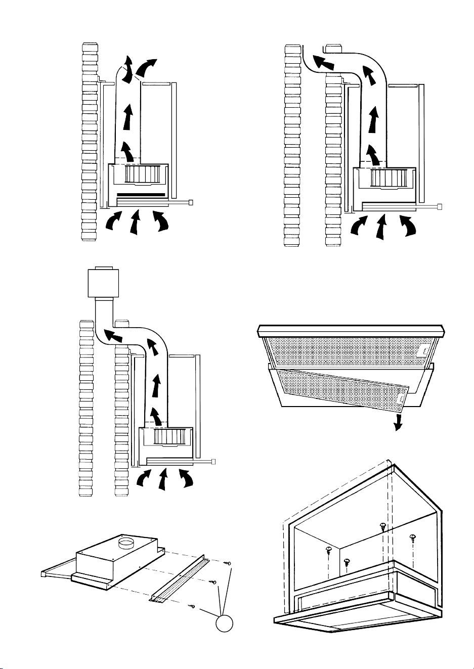
1 2
6
A
5
3
4
7
71
140
42
S
8
C
A
B
9
C
B
D
10
11
B
C
12
A
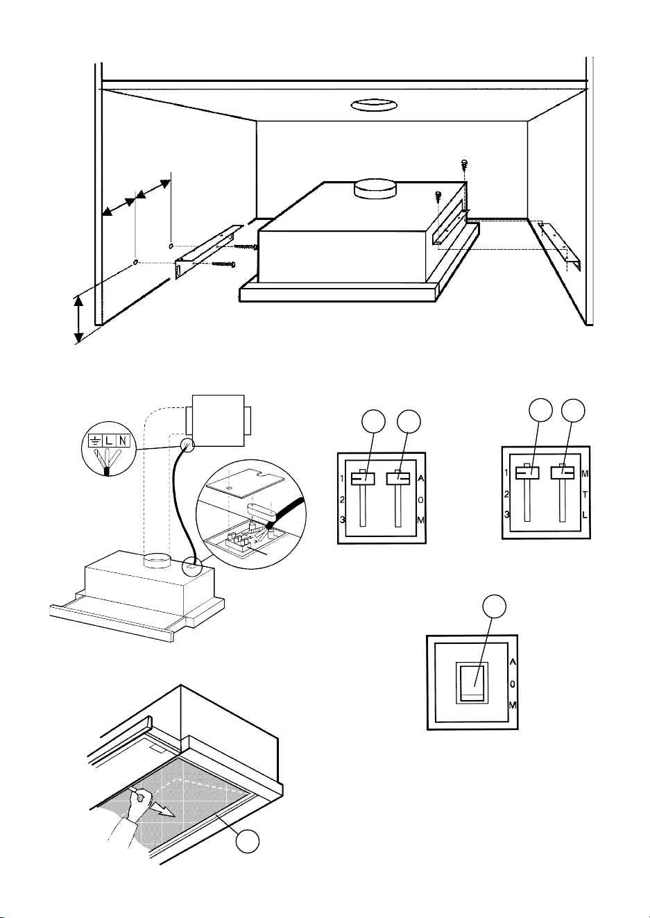
1 2
6
A
5
3
4
7
71
140
42
S
8
C
A
B
9
C
B
D
10
11
B
C
12
A

04306281/5 - 414-98
INSTRUCTIONS POUR L'EMPLOI
INSTRUCTIONS FOR USE
GEBRAUCHSANWEISUNG
ISTRUZIONI PER L'USO
GEBRUIKSAANWIJZING
13
15
14
sovr.04306682
CBT62 - CBT92