Check that the mains voltage matches with the voltage on the data plate inside the canopy rangehood. Check that the installation complies with standards of local building, gas and electrical authorities. Before connecting to the mains supply ensure that the mains voltage corresponds to the voltage on the rating plate inside the cooker hood.
If the supply cord is damaged, it must be replaced by the manufacturer or its service agent or a similarly qualied person in order to avoid a hazard.
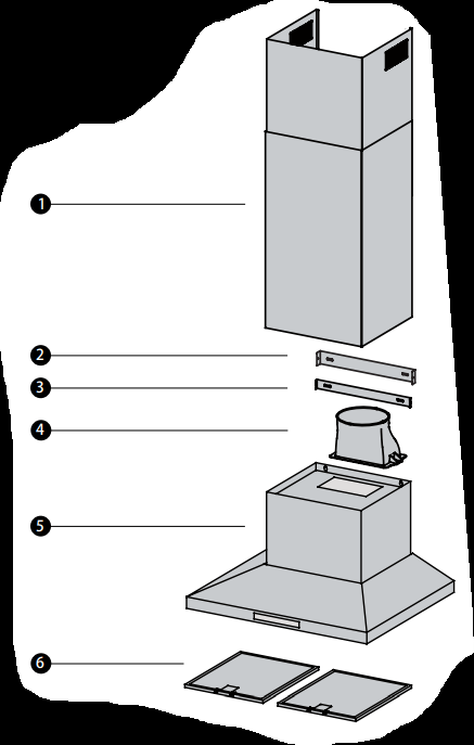
Fixings required to attach rangehood body and anti tilt brackets
Fixings required to attach flue cover mounting brackets
Worm drive clamps, duct tape or cable ties
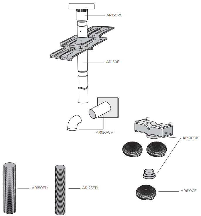
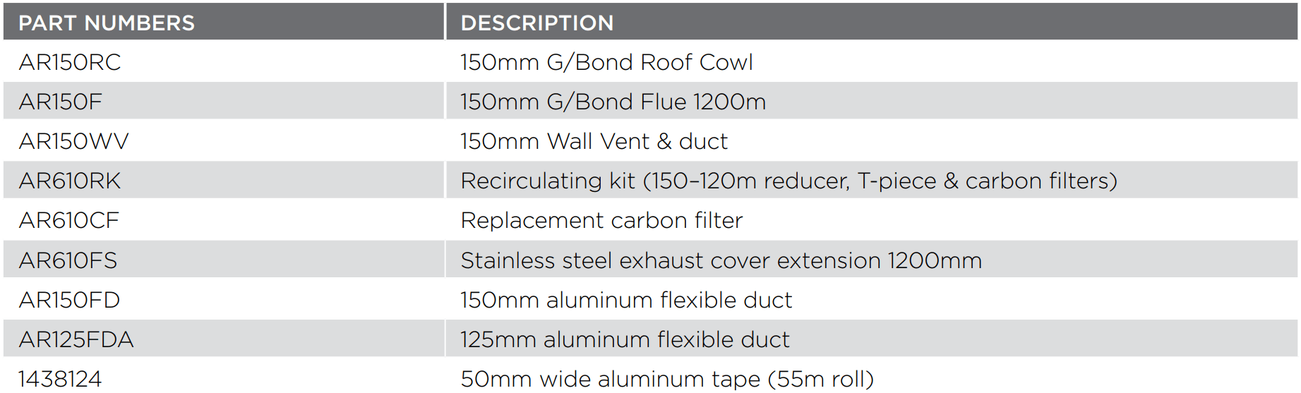
Ducting accessories
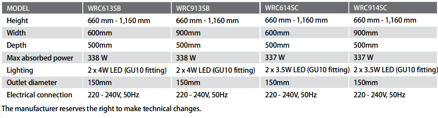
Technical specification
Power supply: 240 V 50 Hz. Connects to 10 A power point
Lights: 2 x 3.5 watt, 240 V LED
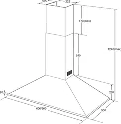
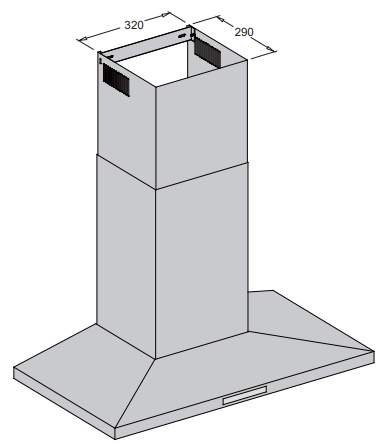
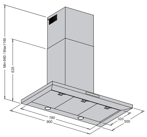
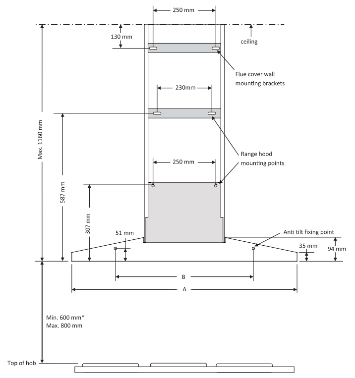
RANGEHOOD DIMENSIONS
INSTALLATION
Pre-installation
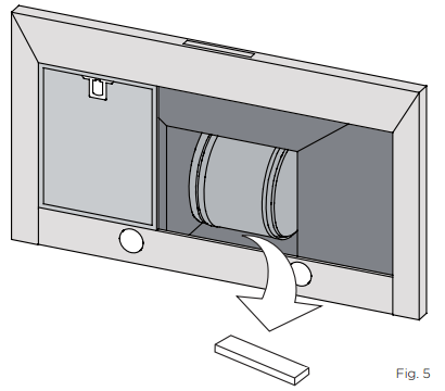
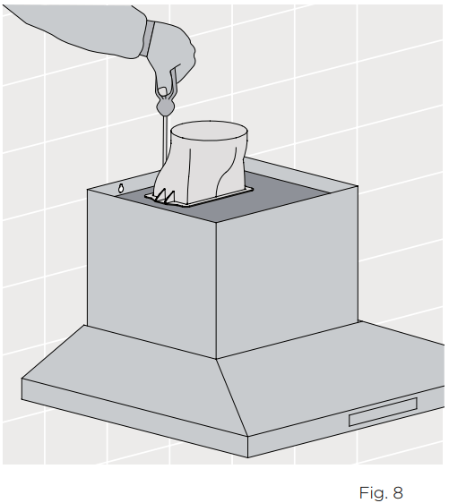
Before installing the cooker hood, peel off any protective plastic covering and remove polystyrene from inside behind the fan motor. See Fig. 5 below
Location
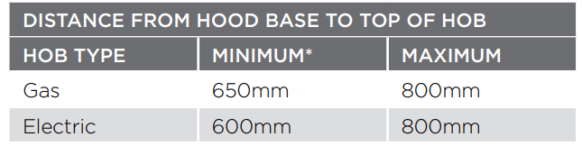
The hood is to be mounted on the wall. When installed, the hood must be not less than 60cm above electric burners or 65cm above gas or mixed-fuel burners.
* If the instructions of the hob specify a greater distance than the minimum above, then that shall be the minimum height for installation.
STEP-BY-STEP INSTALLATION
Step 1. Using a spirit level mark a vertical centre line on the wall where the hood is to be positioned, and a horizontal line at the hood base position. (See Fig. 4, or 5 for relevant model.
NOTE : The height of the underside of the hood body must be a minimum of 600mm* to a maximum height of 800mm .
* If the instructions of the hob specify a greater distance than the minimum above, then that shall be the minimum height for installation.
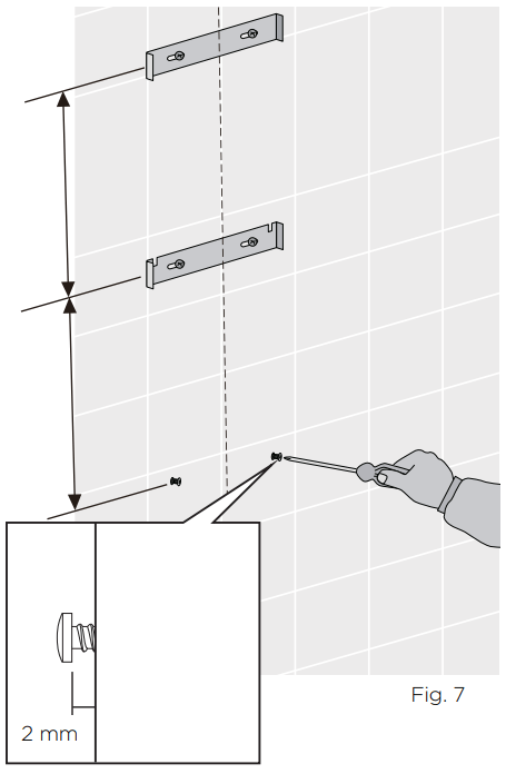
Step 2. Mark the location for the flue cover wall mounting brackets and rangehood mounting points and anti-tilt fixing points above the hood base using the hood base as a reference point
Step 3. Install flue cover wall mounting brackets with suitable fixings. Install suitable screws for rangehood mounting points (to support a total weight of 30kg) to the wall as marked (Fig. 7)
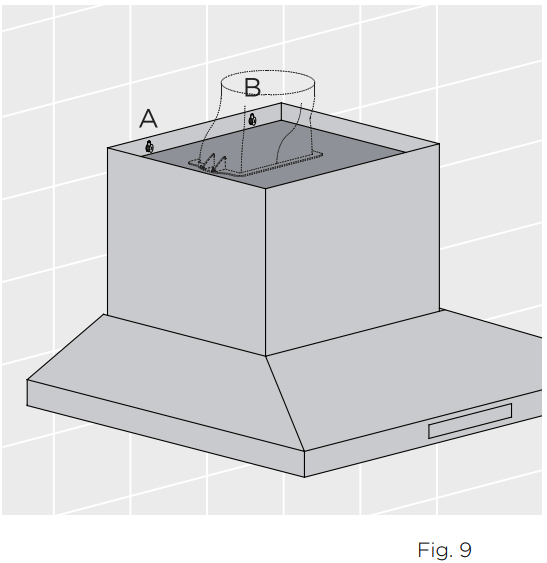
Step 5. Hang the body hood on the mounting screws then secure at the anti-tilt locations as indicated in Fig 9
Depending on the preferred installation/ducting mode, follow step 14a or 14b below
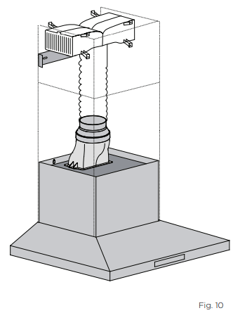
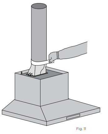
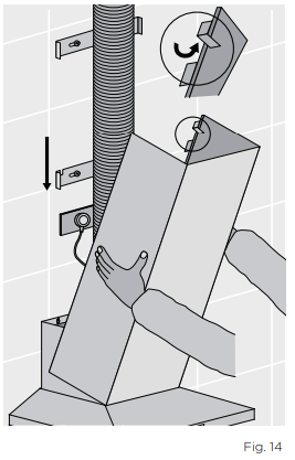
Step 6a. Recirculating mode (Fig. 10). Using the centre line, secure the recirculating T-piece to the wall with suitable screws/fixings (optional kit AR610RK). Install flexible pipe between T-piece and reducer.
Use cable ties or suitable duct tape to secure flexible pipe to T-piece and reducer (Fig. 12)
NOTE: When installed in recirculating mode, it is recommended to use a carbon filter (included in recirculation kit AR610RK) to prevent odours being emitted back into the room.
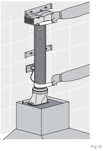
Step 6b. Ducted mode (Fig. 11) Fit a 150mm diameter non combustible flue pipe. Continue the centre line to the ceiling. Fit flue pipe to the exhaust transition duct. Use cable ties or suitable duct tape to secure flue pipe to the transition duct.
Note: For ducted mode we recommend to extend the flue pipe through the roof cladding (with appropriate flashing) to an external roof cowl, venting the exhaust externally.
Some States allow venting into the ceiling cavity, enquiries should be made with the local Government to ensure the installation complies with the regulations.
NOTE: To ensure optimum performance of the rangehood, the use of rigid ducting (optional AR150F) is recommended. The use of bends should be avoided. Rigid flexible ducting is suitable, although loose flexible ducting is unacceptable. All ducting must be fire retardant.
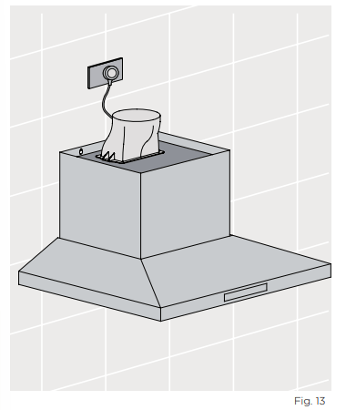
Step 7. Electrical connection
Check that the installation complies with the standards of local building, gas and electrical authorities. Before connecting to the mains supply ensure that the mains voltage corresponds to the voltage on the rating plate inside the rangehood.
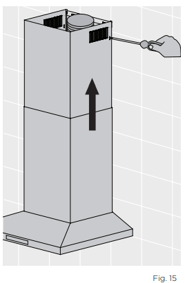
Step 8. Installation of telescopic flue covers
Separate the inner and outer flue covers, and carefully remove the protective coating from both. Carefully reassemble the upper and lower flue covers sections by sliding the inner into the outer flue cover. Carefully lower the assembled upper and lower flue covers onto the top of the rangehood body, and insert the flue cover into the rangehood body approximately 5mm.
Step 9. Fix upper flue cover Fix upper flue cover to the wall mounting bracket with screws supplied. Ensure that the upper section is extended.
WARNING Care must be taken to ensure the screws (supplied in accessories bag) are not cross threaded when attaching the upper flue cover. If installed in recirculating mode, insert the optional carbon filter (included in recirculation kit AR610RK). To complete the cooker hood installation, insert the three filters to the underside of the hood body. Place back edge of filter into position and push up front edge so that the filter clips into place.
Your Electrolux cooker hood is now ready to use.
OPERATION
CONTROL PANEL
Best results are obtained by using a low speed for normal conditions and a high speed when odours are more concentrated.
Turn the hood on for a few minutes before you start cooking.
The hood should be left on for a minimum of 5 minutes after cooking or until all odours have dispersed.
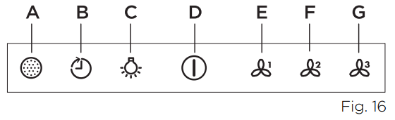
The control switches are located on the front panel of the unit. See Fig. 16 below.
A. Filter
This is the indicator/switch to show when the filter needs to be cleaned.
Once the filters are cleaned the ‘Filter’ alert can be deactivated with a single touch.
B. Timer: Using the Timer
At the end of cooking, if the timer is switched on, the rangehood will continue to run for an additional 5 to minutes, depending on the selected fan speed.
The fan speed is reduced in 5 minute increments until the rangehood turns it self OFF.
If the fan speed is set on high, it will run for 5 minutes then reduce to medium for 5 minutes, then reduce to low for 5 minutes before finally turning it self OFF.
This should ensure the removal of any odours that remain after cooking.
C. Lights: To switch Lights On and OFF
Touch the ‘light’ symbol to turn the lights ON.
Touch the ‘light’ symbol again to turn the lights OFF.
D. Power on/off
E. Fan speed 1: Light frying/boiling
F. Fan speed 2: Frying/wok cooking/heavy boiling
G. Fan speed 3: Grilling, intensive frying and wok cooking
NOTE. This product is fitted with a safety cutout device. If the cooker hood is installed to close to the cooktop, flambe cooking, operating the cooktop without cooking utensils and blocked filters may activate the safety cutout device. If the hood stops during operation, correct the faults and allow time for the safety cutout device to reset, the cooker hood will then function correctly
CARE & MAINTENENCE
CAUTION External surfaces are susceptible to scratches and abrasions, so please follow the cleaning instructions to ensure the best possible result is achieved without damage
Cleaning the hood
Clean the outside of the hood using a damp cloth and a solution of water and mild washing up liquid. Clean stainless steel surfaces using non-abrasive cleaning products that are specifically for use on stainless steel. To ensure the best results also use an even pressure and follow the grain of the stainless steel.
Use of a soft cloth reduces the risk of scratching. If the cloth is wet ensure that a dry soft cloth is used to wipe down the surface and apply stainless steel protector to reduce the risk of any surface rust appearing.
Never use corrosive, abrasive or flammable cleaning products or products containing bleach.
Never insert pointed objects in the motors protective grid.
Only ever clean the switch panel and filter grill using a damp cloth and mild washing up liquid.
It is extremely important to clean the unit and change the filters at the recommended intervals. Failure to do so will cause grease deposits that could cause a fire.
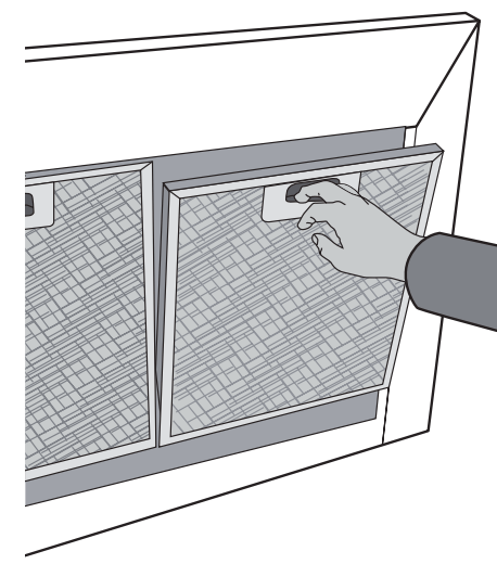
Removing the metal grease filters
Push the grease filter and then pull it down and out
Hand washing
Soak grease filters for about one hour in hot water with a grease-loosening cleaner, then rinse off thoroughly with hot water. Repeat the process if necessary. Refit the grease filters when they are dry.
Dishwasher
Place grease filters in the dishwasher. Select the most powerful washing program and highest temperature, at least 65°C. Repeat the process. Refit the grease filters when they are dry. When washing the metal grease filter in the dishwasher a slight discolouration of the filter can occur, this does not have any impact on it’s performance.
NOTE: The metal grease filters must be removed and washed, either by hand or in the dishwasher, every four weeks
Clean the inner housing using warm water and grease loosening cleaner (never use caustic detergents, abrasive powders or brushes).
Charcoal filter
The charcol filter should only be used if you want to use the hood in the recirculation function.
This filter cannot be cleaned or re-used and as a general rule, the activated charcoal filter should be changed once every four months.
Fitting the charcoal filter
Fit one charcoal filter on the left and one on the right so as to cover the plastic grids that protect the fan wheel. Always specify the hood model code number and serial number when ordering replacement filters. This information is shown on the registration plate located on the inside of this unit.
Replacement charcoal filters can be ordered from your local service centre.
CAUTION There is a fire risk if cleaning is not carried out in accordance with the instructions.
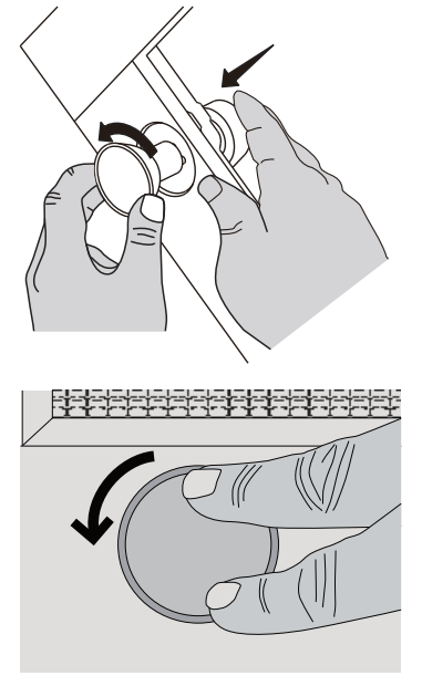
Changing the LED lamps.
If LED lamps need replacing, they must be replaced by lamps as stated in the technical specifications.
Ensure that the appliance is switched off before carrying out maintenance to avoid any possibility of electric shock.
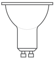
*Suitable lamp for replacement
Lamp type: LED Fixing type: GU10 Voltage: 220~240V AC Power: 3.5W DBR-3.5-H-GU10-50/53
Dimension: o 50mm
TROUBLESHOOTING
PROBLEM
REMEDY
The cooker hood will not start
Check that the hood is connected to an electrical supply
Check that a fan speed has been selected
The cooker hood is not working
Check that the fan speed is set high enough for the task
The grease filters are clean
The kitchen is adequately vented to allow the entry of fresh air
If set up for recirculation, check that the charcoal filter is still effective
If set up for extraction, check that the ducting and outlets are not blocked
Do not operate cooktop without pots/pans
Do not flambe under cooktop
The cooker hood has switched off during operation
The safety cut-out device has been tripped – turn off the hob and wait for the device to reset. Check and clean filters. If the hood has been installed below the heights indicated in the installation instructions the motor will cut out frequently which will damage the hood.
NOTE: This product is fitted with a safety cutout device.
If the cooker hood is installed to close to the cooktop, flame cooking, operating the cooktop without cooking utensils and blocked filters may activate the safety cutout device. If the hood stops during operation, correct the faults and allow time for the safety cutout device to reset, the cooker hood will then function correctly.
 Filter
 Timer: Using the Timer
 Lights: To switch Lights On and OFF
 Power on/off
 Fan speed 1: Light frying/boiling
 Fan speed 2: Frying/wok cooking/heavy boiling
 Fan speed 3: Grilling, intensive frying and wok cooking