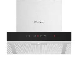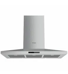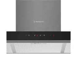
CANOPY RANGEHOOD
WRC914SD
WRC614SD
USER MANUAL
USER MANUAL
CANOPY RANGEHOOD
WRC914SD
WRC614SD
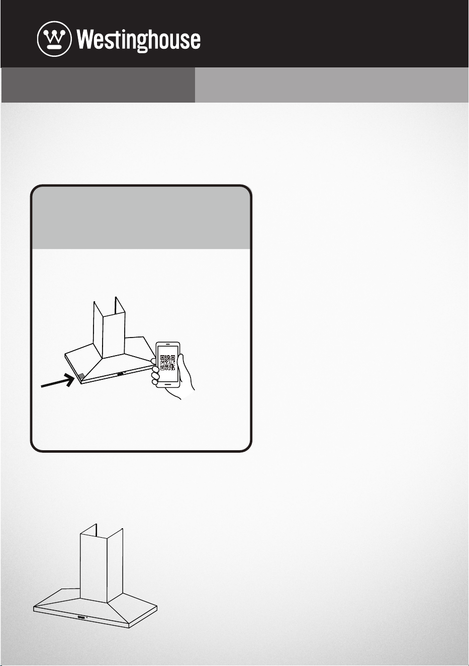
Enjoy peace of mind.
Register your appliance today.
1. Open the camera app on your smartphone and
point at the QR code to scan
Product Registration QR code is located on the
front of your appliance.
2. Tap the notification or link to open the registration from
3. Complete you rdetails and enjoy peace of mind
Stay updated on better living services, safety notices and
shop for accessories.
2
CONGRATULATIONS
Dear Customer,
Congratulations and thank you for choosing
our canopy rangehood. We are sure you
will find your new rangehood a pleasure
to use. Before you use your rangehood,
we recommend that you read through
the whole user manual, which provides
the description of the rangehood and its
function.
To avoid the risks that are always present
when you use an electrical appliance it is
important that the canopy rangehood is
installed correctly and that you read the
safety instructions carefully to avoid misuse
and hazards. We recommend that you keep
this instruction booklet for future reference
and pass it on to any future owners. After
unpacking the canopy rangehood please
check it is not damaged. If in doubt, do not
use the appliance but contact your local
Electrolux Service Centre.
Conditions of use
This appliance is intended to be used in
household and similar applications such as:
• Staff kitchen areas in shops, offices and
other working environments
• Farm houses
• By clients in hotels, motels and other
residential type environments
• Bed and breakfast type environments
• Catering and similar non-retail
applications
Please ensure you read the instruction
manual fully before you call for service, or
a full service fee could be applicable.
Record model and serial number here:
Model number:..............................................................
Serial number: ...............................................................
PNC: ...................................................................................
CONTENTS
Safety instructions ..............................................3
Accessory list ........................................................5
Installation ..............................................................6
Product description .......................................... 13
Daily use ................................................................. 13
Care and cleaning .............................................. 16
Warranty ................................................................. 19
Please read the user manual carefully and
store in a handy place for later reference.
The symbols you will see in this booklet
have these meanings:
WARNING
This symbol indicates information
concerning your personal safety.
CAUTION
This symbol indicates information on how
to avoid damaging the appliance.
IMPORTANT
This symbol indicates tips and information
about use of the appliance.
ENVIRONMENT
This symbol indicates tips and information
about economical and ecological use of the
appliance.
IMPORTANT INFORMATION THAT MAY
IMPACT YOUR MANUFACTURER’S
WARRANTY
Adherence to the directions for use
in this manual is extremely important
for health and safety. Failure to strictly
adhere to the requirements in this
manual may result in personal injury,
property damage and affect your
ability to make a claim under the
Westinghouse manufacturer’s warranty
provided with your product. Products
must be used, installed and operated
in accordance with this manual. You
may not be able to claim on the
Westinghouse manufacturer’s warranty
in the event that your product fault is
due to failure to adhere this manual.
3
SAFETY INSTRUCTIONS
This manual explains the proper use of your new Westinghouse canopy rangehood. Please
read this manual carefully before using the product. This manual should be kept in a safe
place for handy reference. This canopy rangehood is a domestic appliance which has been
manufactured and tested to comply with Australian and New Zealand Standard AS/NZS
60335.1 and AS/NZS 60335.2.31.
IMPORTANT
Check for any damages or marks
If you find the rangehood is damaged or marked, you must report it within 7 days if you
wish to claim for damage/marks under the manufacturers warranty. This does not affect
your statutory rights.
Unpacking
Check that the cooker hood has no damage.Transportation damage should immediately be
reported to the company responsible for the transportation. Damage, faults and missing
details should immediately be reported to the retailer. Take care of the packing materials so
that small children cannot play with them.
ENVIRONMENT
Information on disposal for users
• Most of the packing materials are recyclable. Please dispose of those materials through
your local recycling depot or by placing them in appropriate collection containers.
• If you wish to discard this product, please contact your local authorities and ask for the
correct method of disposal.
• The discharge of air must comply with local authorities regulation.
Warning
• These warnings have been provided in the interest of safety. You MUST read them
carefully before installing or using the appliance.
• The appliance must be plugged into its own dedicated 220-240v, 50Hz AC electrical
outlet.
• This appliance can be used by children aged from 8 years and above and persons with
reduced physical, sensory or mental capabilities or lack of experience and knowledge
if they have been given supervision or instruction concerning the use of the appliance
in a safe way and understand the hazards involved. Children shall not play with the
appliance. Cleaning and user maintenance shall not be made by children without
supervision.
• This canopy rangehood is not recommended for barbecues and cannot be installed for
external use.
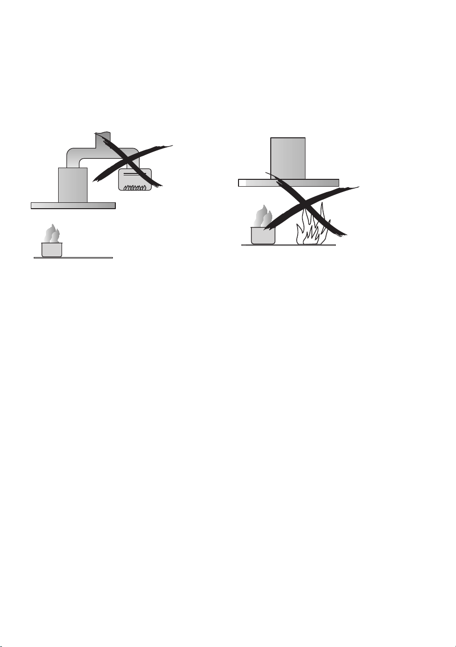
• The exhaust from the canopy rangehood must not be discharged into any heating flue,
which may carry combustion products from other sources. (Fig 1)
• Exhaust air must not be discharged into a wall cavity, unless the cavity is designed for
the purpose.
• There must be adequate ventilation of the room when the canopy rangehood is used at
the same time as appliances burning gas or other fuels.
• Accessible part may become hot when used with cooking appliances.
4
• Always cover lit gas burners with pots or pans when canopy rangehood is in use.
• Always switch off gas burners before you remove pots or pans.
• Do not leave lit gas burners exposed due to the risk of fire.(Fig 2)
• The hood must always be disconnected from the electricity supply before beginning
any maintenance work.
• Failure to install the screws or fixing device in accordance with these instructions may
result in electrical hazards.
Electrical connection
Check that the mains voltage matches with the voltage on the data plate inside the canopy
rangehood. Check that the installation complies with standards of local building, gas and
electrical authorities. Before connecting to the mains supply ensure that the mains voltage
corresponds to the voltage on the rating plate inside the cooker hood.
If the supply cord is damaged, it must be replaced by the manufacturer or its service agent
or similarly qualified person in order to avoid a hazard.
Safety warnings – for the installer
When installing the cooker hood, make sure you adhere to the minimum and maximum
distances from the cooker hood base to the hob surface. (Refer to Installation manual).
Exhaust flue installation: The following rules must be strictly followed to obtain optimal air
extraction.
• Keep exhaust flue short and straight.
• Do not reduce the size or restrict exhaust flue. Keep bends in the exhaust flue to a
minimum.
• When using semi-rigid flue always install duct with helix pulled taut to minimise
pressure loss.
• Failure to observe these basic instructions will drastically reduce the performance and
increase the noise levels of the cooker hood.
Exhaust air must not be discharged into a wall cavity, unless the cavity is designed for that
purpose. The exhaust from the cooker hood must not be discharged into any heating flue,
which may carry combustion products from other sources.
Range hoods and other cooking fume extractors may adversely affect the safe operation of
appliances burning gas or other fuels (including those in other rooms) due to back flow of
combustion gases. These gases can potentially result in carbon monoxide poisoning. After
installation of a range hood or other cooking fume extractor, the operation of flued gas
appliances should be tested by a competent person to ensure that back flow of combustion
gases does not occur.
Fig. 1 Fig. 2
5
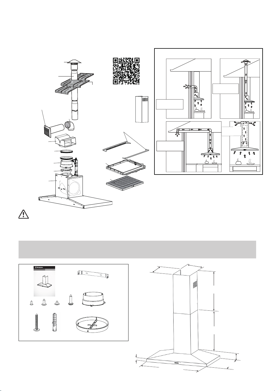
Roof cowl
Flue
1200mm length
Wall vent
(includes 400mm of flue)
90° bend
Plastic diverter
Hose clamp
Duct transition
Non-return flap
Machine
Carbon filter
Plastic frame for
carbon filter
Adaptors for
plastic frame
Flashing
Installation Options
Rea Exhaust to
atmosphere
Side Exhaust
to atmosphere
Recirculating
Installation
Top Exhaust to
atmosphere
For more information on rangehood
accessories scan the QR code below
Extra Length Inner
Flue Cover 1100mm
Warning
Failure to install the screws or fixing device in accordance these instructions may result in
electrical hazards.
ACCESSORY LIST
1x
3x
6x
6x
1x
1x
1x
1x
USER MANUAL
CANOPY RANGEHOOD
WRC914SD
WRC614SD
*These accessories are supplied with product
A
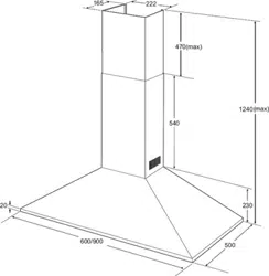
598/898
NOTE: Some installations may require the telescopic exhaust cover to be cut to length. Cut with
sharp tin snips or a fine-tooth hack saw blade, taking care not to distort or dent the exhaust cover.
Some additional accessories may be required for installation
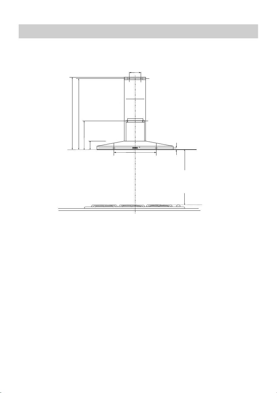
40
500
100
565
550 (max)
252
278
2x
6
INSTALLATION
Before installing the cooker hood, peel off any protective plastic covering.
120
100
200
369
B
500
31
Min: 670 max 1215
Min: 655 max 1200
Note
If the instructions of the hob
specify a greater distance than
the minimum, then that shall
be the minimum height for the
installation
Note
Some installation may require telescopic flue cut to length. Cut with tin snips or a fine-
tooth hack saw blade, taking care not to distort or dent flue.
All the holes on the wall are Ø6mm.
The height of the top of the pan supports (top of the trivets) of a gas cooking appliance
with respect to the bench top (built in) or supporting surface (elevated) or the floor
(freestanding) will be detailed in the gas cooking appliance instructions.
Diagram B:
Recommended working heights. Flue mounting bracket locations. Telescopic flue cover
fixing points.
Hood Base
DIMENSIONS ARE IN MILLIMETRES
DIMENSIONS ARE IN MILLIMETRES
Top of trivet
Minimum
600 Electric
620 Gas
Maximum
800 mm
7
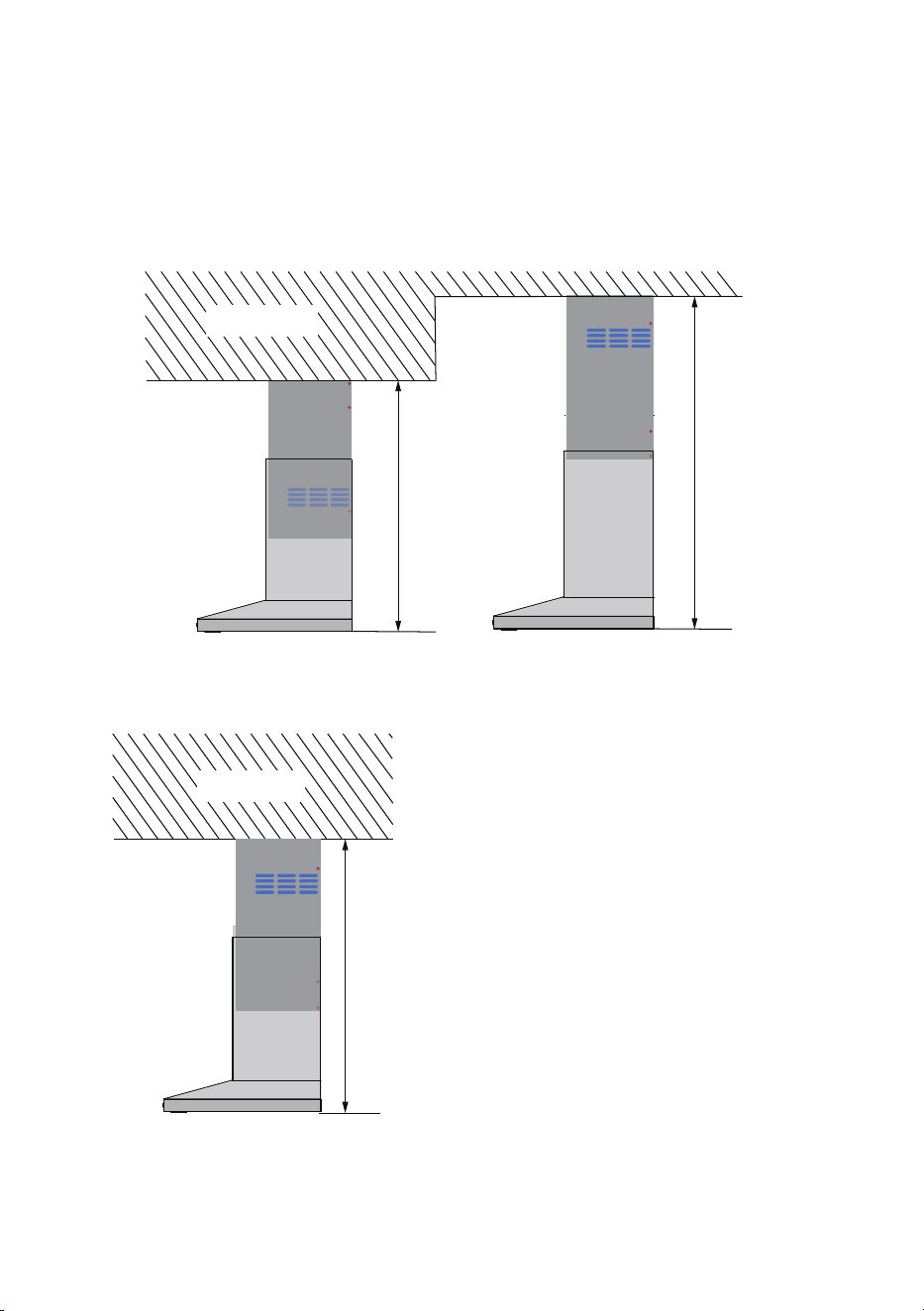
Recommended installation mode
For External exhaust mode installation
• Type ① is recommended when the distance from the ceiling to the bottom of the hood
is < 900 mm.
• Type ② is recommended when the distance from the ceiling to the bottom of the hood
is ≥ 900 mm.
①
②
<900mm
≥900mm
Ceiling
For recirculation mode installation
The distance from the ceiling to the bottom of the hood is ≥ 880mm, see image ③.
③
H≥880mm
Ceiling
8
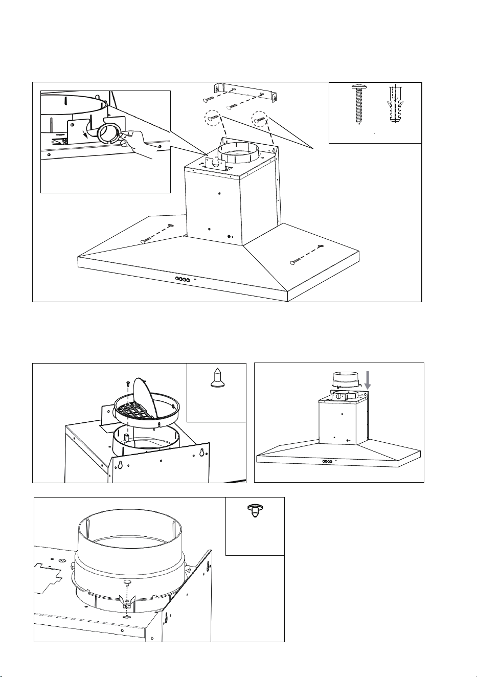
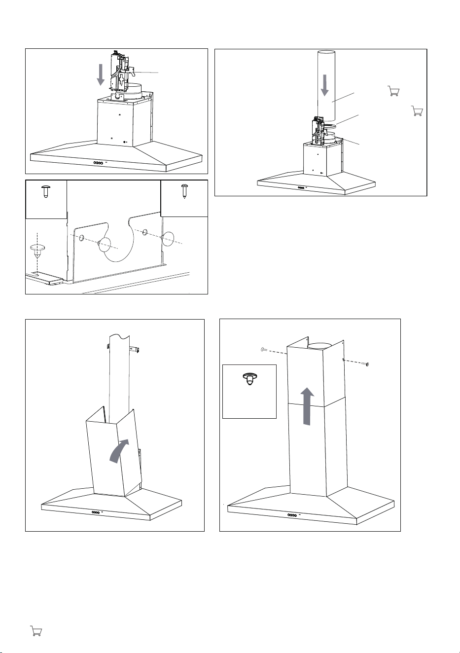
Recommended installation sequence
External exhaust mode installation
C1
6X
WOOD SCREWS Ø4*30
WALL PLUG Ø6
Diagram C1
• Install cooker hood body. Determine working height, mark wall to suit. Install flue cover mounting
brackets.
• Ensure the screws highlighted in “C1” have 3mm gap between screw head and wall, this will ensure
suffcient space for body fitment.
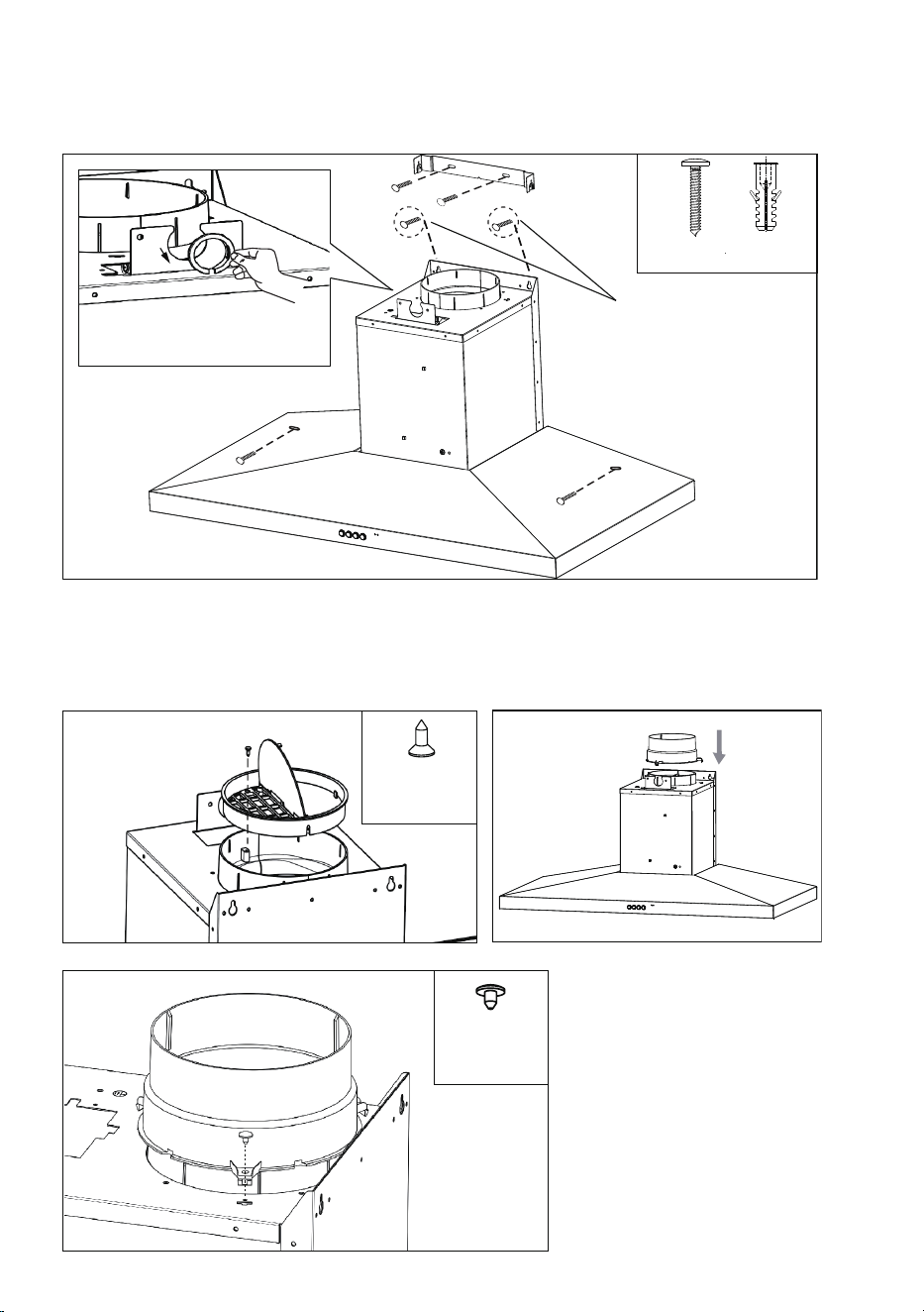
D1
E1
F1
1X
ST 4.2*6.5mm
1X
ST 2.9*9.5mm
Diagram D1
• Fit the non-return valve to the outlet of
the range hood.
• Fasten the non-return valve with the
screw supplied to ensure the non-return
valve is securely fastened.
Diagram E1
• Insert the three clips of Duct transition
into product
Diagram F1
• Fasten the Duct transition with the
screw supplied to ensure the Duct
transition is securely fastened.
* Leave 3mm gap between
screw head and wall
Take the ring off before installing, it
is for transportation only and may
be disposed of.
9
G1 I1
H1
J1
K1
2x
ST 3.2*13mm
1X
ST 4.2*12mm
2X
ST 4.2*6.5mm
Diagram G1
• Insert the clip of power box into product
Diagram H1
• Fasten the power box with the screws supplied to ensure
the power box is securely fastened.
Diagram I1
• Loosen the hose clamp and put it outside of Duct
transition
• Fit the flue over the outer wall of Duct transition
• Tighten the hose clamp with a screwdriver to secure to
Duct transition.
Diagram J1
• Install bottom section of telescopic flue
cover.
Diagram K1
• Install top section of telescopic flue cover
and fasten the cover with supplied screws.
Flue
Hose clamp
Duct transition
Power box
*
*
:sourced locally
10
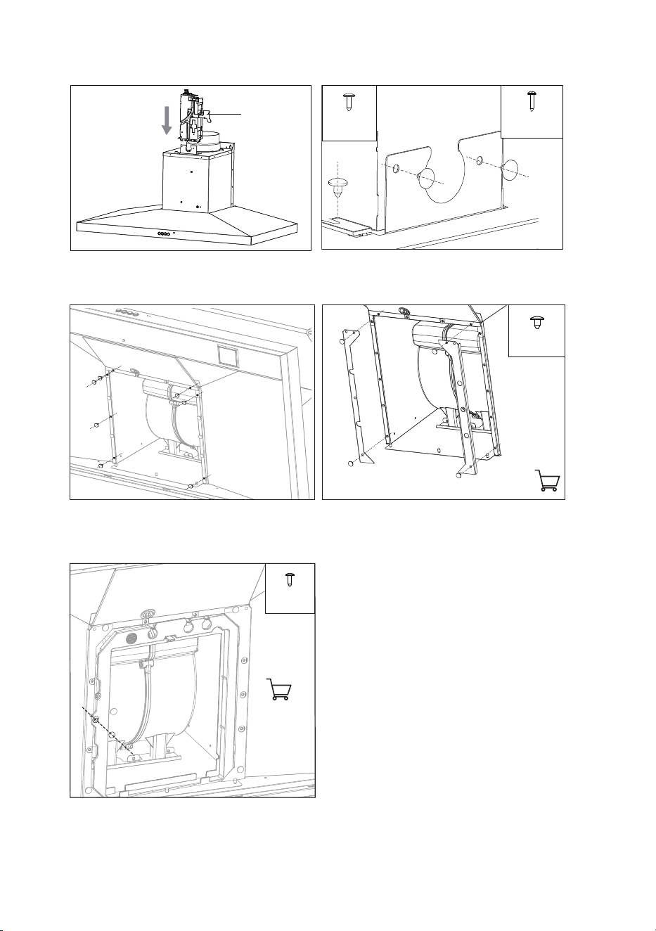
Recommended installation sequence
Recirculation mode installation
C2
6X
WOOD SCREWS Ø4*30
WALL PLUG
Diagram C2
• Install cooker hood body. Determine working height, mark wall to suit. Install flue cover mounting
brackets.
• Ensure the screws highlighted in “C2” have 3mm gap between screw head and wall, this will ensure
sufficient space for body fitment.
D2
E2
F2
1X
ST 4.2*6.5mm
1X
ST 2.9*9.5mm
Diagram D2
• Fit the non-return valve to the outlet of
the range hood.
• Fasten the non-return valve with the
screw supplied to ensure the non-return
valve is securely fastened.
Diagram E2
• Insert the three clips of Duct transition
into product
Diagram F2
• Fasten the Duct transition with the
screw supplied to ensure the Duct
transition is securely fastened.
* Leave 3mm gap between
screw head and wall
Take the ring off before installing, it
is for transportation only and may
be disposed of.
11
G2
H2
2x
ST 3.2*13mm
1X
ST 4.2*12mm
I2-1
4X
ST 4.2*6.5mm
I2-2
J2
1X
ST 4.2*12mm
Diagram G2
• Insert the clip of power box into product
Diagram J2
• Fasten the plastic for carbon filter with the screw
supplied.
Diagram I2-1
• First loosen the seven screws shown in
the figure.
Diagram I2-2
• Fasten the adaptors for plastic frame
with the screws supplied housing.
Power box
12
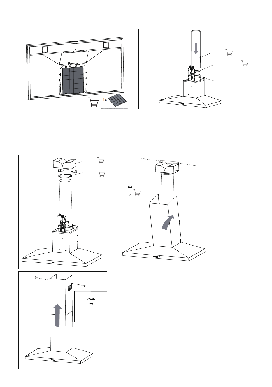
L2
K2
O2
N2
M2
2 X
ST 4.2*6.5mm
2 X
ST 3.2*13mm
Diagram K2
• Install Carbon filter
Diagram L2
• Loosen the hose clamp and put it outside of Duct transition
• Fit the flue over the outer wall of Duct transition
• Tighten the hose clamp with a screwdriver to secure to Duct transition.
Diagram M2
• Tightening the hose clamp with plastic diverter.
Diagram N2
• Install bottom section of telescopic flue cover, tighten
the plastic diverter and the bracket.
Diagram O2
• Install top section of telescopic flue cover and fasten
the cover with supplied screws.
Flue
Hose clamp
Duct transition
Diagram H2
• Fasten the power box with the screws
supplied to ensure the power box is
securely fastened
Plastic
diverter
Hose
clamp
13
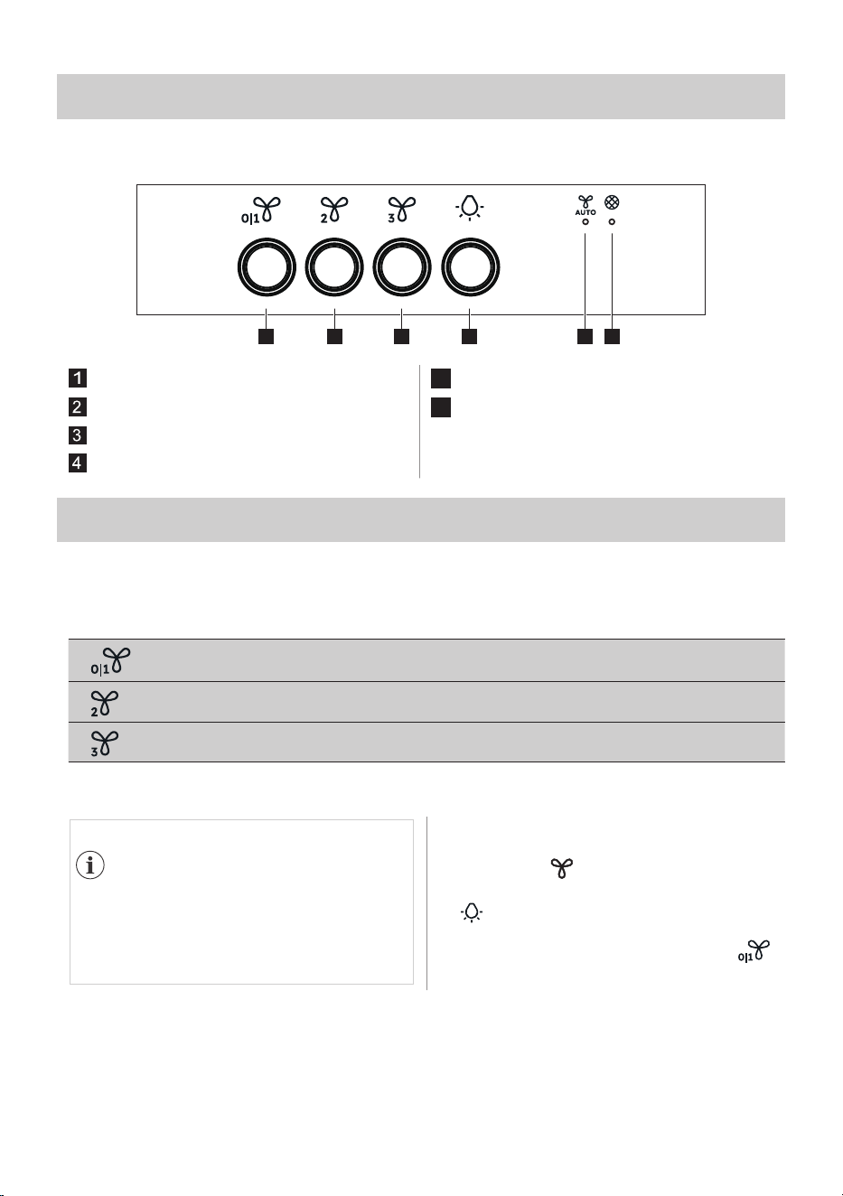
PRODUCT DESCRIPTION
Control panel overview
32 41 5 6
Fan Speed 1 /Off
5
Hob2Hood Indicator
Fan Speed 2
6
Filter Notification Indicator
Fan Speed 3
Light
DAILY USE
Use the hood
Check the recommended speed according to the table below
While heating up food, cooking with covered pots, light frying, light boiling.
While cooking with covered pots on multiple cooking zones or burners,
frying, boiling.
While boiling, frying big quantities of food without a lid, cooking on
multiple cooking zones or burners, grilling, intensive frying, wok cooking.
It is recommended to leave the hood
operating for approximately 15 minutes
before cooking to kick-start airflow in the
kitchen.
To operate the hood:
1. Turn on the appliance by pressing the
fan button
2. If needed, pressing the light button
to illuminate the cooking surface.
3. To turn off the appliance press the fan
button again or long pressing the
button.
14
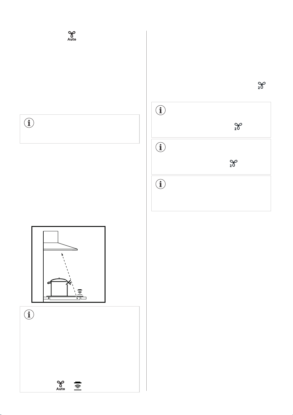
Hob2Hood*
* It is an automatic function which
connects the hob with a hood. Both the
hob and the hood have an infrared signal
communicator. Speed of the fan is defined
automatically on basis of mode setting
and temperature of the hottest cookware
on the hob. You can also operate the fan
using he hob manually. The function can
be activated from panel of the hob.
*For applicable models only.
For more information how to use the
function refer to the hob user manual.
Hints and Tips for Hob2Hood function
When you operate the hob with
Hob2Hood function:
• Protect the hood panel from direct
sunlight.
• Do not spot halogen light on the hood
panel.
• Do not cover the hob panel.
• Do not interrupt the signal between
the hob and the hood (for example
with a hand or a cookware handle).
It may happen that other remote
controlled appliances may block the
signal. To avoid it do not operate the
remote of the appliance and the hob at
the same time.
To find the full range of rangehoods
which work with this function refer to
our consumer website. The rangehoods
that work with this function must have
the symbol or
Activate and deactivate the
filter notification
1. Switch on the control panel.
2. Make sure that the Fan Speed is
turned off.
3. To activate or deactivate the carbon
filter press button 'Fan Speed 2'
for 5 seconds.
When the Carbon Filter Notification
is enabled, the Fan Speed 2
flashes(white) for a few seconds.
When the Carbon Filter Notification is
disabled, the Fan Speed 2 lights
up(white) for a few seconds.
Please do not enable "Carbon Filter
Notification" when not using the hood in
recirculation configuration.
Activate and deactivate the
Sound Profile
To activate or deactivate the Sound Profile
press button 'Light' for 2 seconds. The
'Light' flashes(white) once if sounds
are enabled and twice if sounds are
disabled.
Please reset Filter Notification first when
Filter Notification is activated on the
hood UI.
Filter Alarms
The filter alarm is a reminder to change
the carbon filter and clean the grease
filter. The filter indicator is turned on
(white) for 30 seconds if the grease filter
must be cleaned.
The filter indicator flashes (white) for
30 seconds if the carbon filter must be
replaced.
Filter alarm Reset
Refer to activating and deactivating the
filter alarm in daily use chapter.
Refer to cleaning the grease filter in this
chapter.
Refer to replacing the carbon filter
(depends on filter type).
To reset the alarm:
Press the button 'Fan Speed 3' for 2
seconds .
To reset the function counter for Filter
Notification out of notification period:
For Grease Filter press 'Fan Speed 3'
for 2 seconds.
For Carbon Filter press 'Fan Speed 2'
and 'Fan Speed 3' at the same time
for 2 seconds.
The Indicator flashes once for correct
reset.
15
16
CARE AND CLEANING
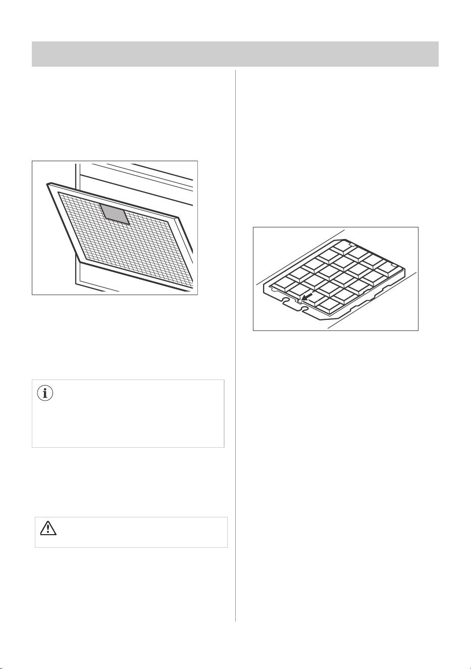
Clean the grease filter
Each filter must be cleaned at lease once a
month. Filter are mounted with the use of
clips and pins on the opposite side.
To clean the filter:
1. Press the handle of the mounting clip on
the filter panel underneath the hood (1).
2. Slightly tilt the front of the filter down-
wards (2), then pull.
Repeat the first two steps for all filter.
3. Clean the filters using a sponge
with nonabrasive detergents or in a
dishwasher.
The dishwasher must be set to a low
temperature and a short cycle. The grease
filter may discolour, it has no influence on
the performance of the appliance.
4. To mount the filters back follow the first
two steps in reverse order.
Repeat the steps for all filters if
applicable.
Replace the carbon filter
WARNING!
The carbon filter is non-washable!
The time of saturation of the carbon filter
varies depending on th type of cooking
and the regularity of cleaning the grease
filter.
1. Remove the grease filters from the
appliance to access the carbon filter.
Refer to “Cleaning the grease filter” in this
chapter.
2. To remove the carbon filter,
press the tab (1) and slightly
tilt the front of the filter.
11
3. To install a new filter, perform the same
steps in reverse order.
Replace the carbon filters at least every 4
months.
Replace the Light
This appliance is supplied with two LED
Lights. These parts can be replaced by a
technician only. Replace with MAX 2.4W
LED Light. Suitable Light for replacement:
Square LED 700mA MAX 2.4w 3V 3000K.
Size: 53mm x 53mm

17
Note
This product is fitted with a safety cutout device. The cutout device may activate if follow
occurs;
• Hood installed too close to cooktop
• Flambe cooking
• Operation of the cooktop without utensils covering burners hot plates
• Blocked filters.
If the cooker hood stops during operation, correct the items noted above and allow time for
safety cutout device to reset. Once the safety device has reset the cooker hood will then
function.
18
NOTE

Warranty
FOR SALES IN AUSTRALIA AND NEW ZEALAND
APPLIANCE: WESTINGHOUSE RANGEHOODS
This document sets out the terms and conditions of the
product warranties for Westinghouse Appliances. It is an
important document. Please keep it with your proof of
purchase documents in a safe place for future reference
should there be a manufacturing defect in your Appliance.
This warranty is in addition to other rights you may have
under the Australian Consumer Law.
1. In this warranty:
(a) 'ACL' or 'Australian Consumer Law' means Schedule 2 to
the Competition and Consumer Act 2010;
(b) 'Appliance' means any Bectrolux product purchased by
you and accompanied by this document;
(c) 'ASC' means Electrolux authorised serviced centres;
(d) 'Westinghouse' is the brand controlled by Electrolux
Home Products Pty Ltd of 163 O'Riordan Street, Mascot
NSW 2020, ABN 51 004 762 341 in respect of Appliances
purchased in Australia and Electrolux (NZ) Limited
(collectively "Electrolux") of 3-5 Niall Burgess Road,
Mount Wellington, in respect of Appliances purchased in
New Zealand;
(e) 'Warrarrty Period' means the period specified in clause 3
of this warranty;
(f) 'you' means the purchaser of the Appliance not having
purchased the Appliance for re-sale, and 'your' has a
corresponding meaning.
2. Application: This warranty only applies to new Appliances,
purchased and used in Australia or New Zealand and is in
addition to (and does not exclude, restrict, or modify in any
way) other rights and remedies under a law to which the
Appliances or services relate, including any non-excludable
statutory guarantees in Australia and New Zealand.
3. Warranty Period: Subject to these terms and conditions,
this warranty continues for in Australia for a period of
24 months and in New Zealand for a period of 24 months,
following the date of original purchase of the Appliance.
4. Repair or replace warranty: During the Warranty Period,
Electrolux or its ASC will, at no extra charge if your
Appliance is readily accessible for service, without special
equipment and subject to these terms and conditions, repair
or replace any parts which it considers to be defective.
Electrolux may, in its absolute discretion, choose whether
the remedy offered for a valid warranty claim is repair or
replacement. Bectrolux or its ASC may use refurbished
parts to repair your Appliance. You agree that any replaced
Appliances or parts become the property of Electrolux.
5. Travel and transportation costs: Subject to clause 7,
Electrolux will bear the reasonable cost of transportation,
travel and delivery of the Appliance to and from Electrolux
or its ASC. Travel and transportation will be arranged by
Electrolux as part of any valid warranty claim.
6. Proof of purchase is required before you can make a claim
under this warranty.
7. Exclusions: You may not make a claim under this warranty
unless the defect claimed is due to faulty or defective parts
or workmanship. This warranty does not cover:
(a) light globes, batteries, filters or similar perishable parts;
(b) parts and Appliances not supplied by Electrolux;
(c) cosmetic damage which does not affect the operation
of the Appliance;
(d) damage to the Appliance caused by:
(i) negligence or accident;
(ii) misuse or abuse, including failure to properly
maintain or service;
(iii) improper, negligent or faulty servicing or repair
works done by anyone other than an Electrolux
authorised repairer or ASC;
(iv) normal wear and tear;
(v) power surges, electrical storm damage or
incorrect power supply;
(vi) incomplete or improper installation;
(vii) incorrect, improper or inappropriate operation;
(viii) insect or vermin infestation;
(ix) failure to comply with any additional instructions
supplied with the Appliance;
In addition, Electrolux is not liable under this warranty if:
(a) the Appliance has been, or Electrolux reasonably
believes that the Appliance has been, used for purposes
other than those for which the Appliance was intended,
including where the Appliance has been used for any
non-domestic purpose;
(b) the Appliance is modified without authority from
Electrolux in writing;
(c) the Appliance's serial number or warranty seal has been
removed or defaced
8. How to claim under this warranty: To enquire about
claiming under this warranty, please follow these steps:
(a) carefully check the operating instructions, user manual
and the terms of this warranty;
(b) have the model and serial number of the Appliance
available;
(c) have the proof of purchase (e.g. an invoice) available;
(d) telephone the numbers shown below.
9. Australia: For Appliances and services provided by
Electrolux in Australia: Electrolux goods come with
guarantees that cannot be excluded under the Australian
Consumer Law. You are entitled to a replacement or refund
for a major failure and for compensation for any other
reasonably foreseeable loss or damage. You are also entitled
to have the Appliance repaired or replaced if the Appliance
fails to be of acceptable quality and the failure does not
amount to a major failure. 'Acceptable quality' and 'major
failure' have the same meaning as referred to in the ACL.
10. New Zealand: For Appliances and services provided by
Electrolux in New Zealand, the Appliances come with a
guarantee by Electrolux pursuant to the provisions of the
Consumer Guarantees Act, the Sale of Goods Act and the
Fair Trading Act. Where the Appliance was purchased
in New Zealand for commercial purposes the Consumer
Guarantee Act does not apply.
11. Confidentiality: You accept that if you make a warranty
claim, Electrolux and its agents including ASC may
exchange information in relation to you to enable Electrolux
to meet its obligations under this warranty.
Important Notice
Before calling for service, please ensure that the steps listed in clause 8 above have been followed.
AUSTRALIA
FOR SERVICE
or to find the address of your nearest
authorised service centre in Australia
PLEASE CALL 13 13 49
For the cost of a local call
FOR SPARE PARTS
or to find the address of your nearest
spare parts centre in Australia
PLEASE CALL 13 13 50
For the cost of a local call
NEW ZEALAND
FOR SERVICE
or to find the address of your nearest
authorised service centre in New Zealand
PLEASE CALL 0800 10 66 10
FOR SPARE PARTS
or to find the address of your nearest
spare parts centre in New Zealand
PLEASE CALL 0800 10 66 20
WRange_War_Jul19
19

For more information on all Westinghouse
appliances, or for dimension and installation
information, call into your retailer, phone or email
our customer care team or visit our website:
AUSTRALIA
phone: 13 13 49
email: customercare@electrolux.com.au
web: westinghouse.com.au
NEW ZEALAND
phone: 0800 10 66 10
email: customercare@electrolux.co.nz
web: westinghouse.co.nz
and WESTINGHOUSE are trademarks of Westinghouse Electric Corporation.
Used under license by Electrolux Home Products Pty Ltd. All Rights Reserved.
© 2023 Electrolux Home Products Pty Ltd.
ABN 51 004 762 341
WMAN_Pyramid_Nov2023
ANC: 305466408_B