Owner’s Manual
Vitality™ Series Selectorized Line


Vitality Series Selectorized Line Owner's Manual: Important Safety Guidelines for Owners 1
Follow these guidelines to maintain proper working condition of the
equipment:
Important: Do not modify the equipment or any of its parts, or permanently remove
any part from the equipment. Do not use accessory attachments that are not
recommended by Precor, as such attachments might cause injuries.
Qualified technicians must perform all regular maintenance.
Check that all fasteners are securely tightened. Cables should be secured
at both end connections and properly threaded. Weight stacks should be
secure and functioning properly. Handle attachments should be properly
connected.
Make sure that trainers, facility personnel, and maintenance technicians
understand how to use the equipment, know important safety guidelines,
and can recognize potential problems such as a worn cable, loose
hardware, or cracked weld.
Strength training requires a significant focus by the facility and its staff to
maintain the quality of the fitness environment. If possible, the facility
should provide direct supervision of the fitness equipment at all times by
people knowledgeable about the safe operation of the equipment and
trained to recognize potential problems.
If any staff member witnesses unsafe use of the equipment, he or she
should address the user directly, demonstrate the proper technique, and
review the Important Safety Information for Users. Precor recommends posting
a copy of the Important Safety Information for Users near the equipment in a
prominent location.
Make sure the equipment is stable and placed on a solid surface. The
equipment is designed to be freestanding; however, it can be bolted to the
floor for extra stability. Precor highly recommends that the equipment be
bolted to the floor to reduce the risk of toppling the equipment due to
improper use. Since floor construction varies, please consult a professional
building engineer for proper fastening.
Locate the equipment at least 40 inches (1 meter) away from walls or
furniture on either side of the equipment, and 40 inches (1 meter) away
from objects behind the equipment. For Functional Training equipment,
make sure that the operating space is large enough to allow the cables to
be fully extended in all possible directions.
Check the equipment thoroughly based on the recommended inspection
schedules outlined in this manual, including daily, weekly, monthly and
annual checks. Ensure all bolt connections are tight and that the threaded
cables are properly and tightly secured at both ends.
Place an “out-of-order” sign on the equipment during maintenance of the
equipment or the surrounding area. Users should never be allowed to
operate the equipment until it has been inspected and works properly. If a
piece of equipment needs service, keep it out of use until it is repaired.
When working with the weight stacks, do not attempt to free any jammed
assemblies without assistance as this may cause injury. With the help of
another person, carefully return the weight stack to the proper position
with the top plate resting on the first weight.
Do not allow the equipment to be used if the top plate or weight stack is
pinned in a raised position. With the help of another person, carefully
return the equipment to the proper position with the top plate resting on
the first weight. Inspect the cable to make sure that it is seated in all of the
pulleys.
Do not place the equipment outdoors or on wet surfaces.
Important Safety Guidelines for Owners

Vitality Series Selectorized Line Owner's Manual: Important Safety Guidelines for Owners 2
Safety Approval
Precor commercial strength equipment is designed and tested according to EN
957-1/2 standards.
Obtaining Service
You should not attempt to service the strength equipment, except for the
maintenance tasks described in this manual. If any items are missing, contact
your dealer. If you need more information regarding customer support
numbers or a list of Precor authorized service centers, visit the Precor website
at www.precor.com.
If you have any questions regarding a piece of equipment, locate its serial
number and contact Precor Customer Support. Precor uses the serial number
to establish the model and year of the product. You can generally find the
serial number on one of the weight tower uprights.
For future reference, write the serial numbers, model numbers, and dates of
purchase for your Precor strength training equipment in the space provided.
You may want to list all equipment information below for easy reference.
Model #: Serial #:
Date purchased:
Model #: Serial #:
Date purchased:
Model #: Serial #:
Date purchased:
Model #: Serial #:
Date purchased:
Model #: Serial #:
Date purchased:
Model #: Serial #:
Date purchased:
Model #: Serial #:
Date purchased:
Model #: Serial #:
Date purchased:
Model #: Serial #:
Date purchased:
Model #: Serial #:
Date purchased:
Model #: Serial #:
Date purchased:

Vitality Series Selectorized Line Owner's Manual: Important Safety Information for Users 3
Before beginning any fitness program, you should obtain a complete physical
examination from your physician.
French equivalent of the preceding paragraph, for the Canadian market: Il est
conseillé de subir un examen médical complet avant d’entreprendre tout programme
d’exercise. Si vous avez des étourdissements ou des faiblesses, arrêtez les exercices
immédiatement.
When using exercise equipment, you should always take basic precautions,
including the following:
If you do not understand how to operate a piece of equipment, ask
someone from the facility such as a trainer to demonstrate how to use it
and explain any safety instructions.
Do not allow children on or near the equipment. Do not leave children
unsupervised around the equipment.
Use the equipment only for its intended purpose. Do not use accessory
attachments that are not recommended by the manufacturer, as such
attachments may cause injuries.
Wear proper exercise clothing and shoes for your workout—no loose
clothing.
Do not overexert yourself or work to exhaustion. Use reasonable
judgment when working with weights. Avoid using excessive weight,
which may cause injury.
If you feel pain, faintness, dizziness, or abnormal symptoms, stop
exercising immediately and consult your physician.
Keep head, limbs, fingers, and hair clear of all moving parts while the
equipment is in use. Keep hands clear of racking pegs.
Never drop or insert objects into any opening in the equipment.
Check that all fasteners are securely tightened. Cables should be secured
at both end connections and properly threaded. Weight stacks should be
secure and functioning properly. Handle attachments should be properly
connected. Pay particular attention to the condition of cables and cable
ends. If you notice a loose cable end or any fraying of the cable or cable
jacket, do not use the product and contact someone in the facility
immediately.
Always check the equipment before using it. If you spot a potential
problem, contact someone in the facility immediately. Do not use the
equipment until the facility has verified that the equipment is working
properly. Do not attempt to fix broken or jammed equipment.
Do not use the equipment outdoors or on wet surfaces.
Do not drop or slam the weight stack while exercising.
Be sure the selector pin is completely inserted. Use only the pin provided
by the manufacturer. If unsure, contact someone in the facility.
Never pin the weights in an elevated position. Do not use the equipment if
the top plate or weight stack is pinned in a raised position. Notify the
facility’s personnel to repair the equipment and ensure that it is working
properly.
Do not use the equipment if an "out of order" sign has been placed on it.
Read all posted instructions, including all safety instructions and warnings.
Important Safety Information for Users

Vitality Series Selectorized Line Owner's Manual: Table of Contents 4
Important Safety Guidelines for Owners .................................... 1
Safety Approval ...................................................................................... 2
Obtaining Service .................................................................................. 2
Important Safety Information for Users ..................................... 3
Product Specifications and Use .................................................. 5
Leg Extension / Leg Curl ...................................................................... 5
Leg Extension .......................................................................................... 7
Seated Leg Curl ..................................................................................... 8
Leg Press / Calf Extension ..................................................................9
Inner / Outer Thigh .............................................................................. 11
Biceps Curl / Triceps Extension ...................................................... 13
Biceps Curl ............................................................................................. 15
Triceps Extension ................................................................................ 16
Multi-Press ............................................................................................ 17
Chest Press ............................................................................................ 19
Shoulder Press ..................................................................................... 20
Pulldown / Row .................................................................................... 21
Pulldown ................................................................................................ 23
Seated Row ........................................................................................... 24
Rear Delt / Pec Fly ............................................................................. 25
Abdominal / Back Extension ........................................................... 27
Abdominal ............................................................................................ 29
Back Extension .................................................................................... 30
Maintenance .............................................................................. 31
Before You Begin ................................................................................. 31
Daily Inspection .................................................................................. 33
Weekly Inspection .............................................................................. 37
Monthly Inspection ............................................................................. 41
Annual Maintenance ......................................................................... 43
Table of Contents
Vitality Series Selectorized Line Owner's Manual: Product Specifications and Use 5
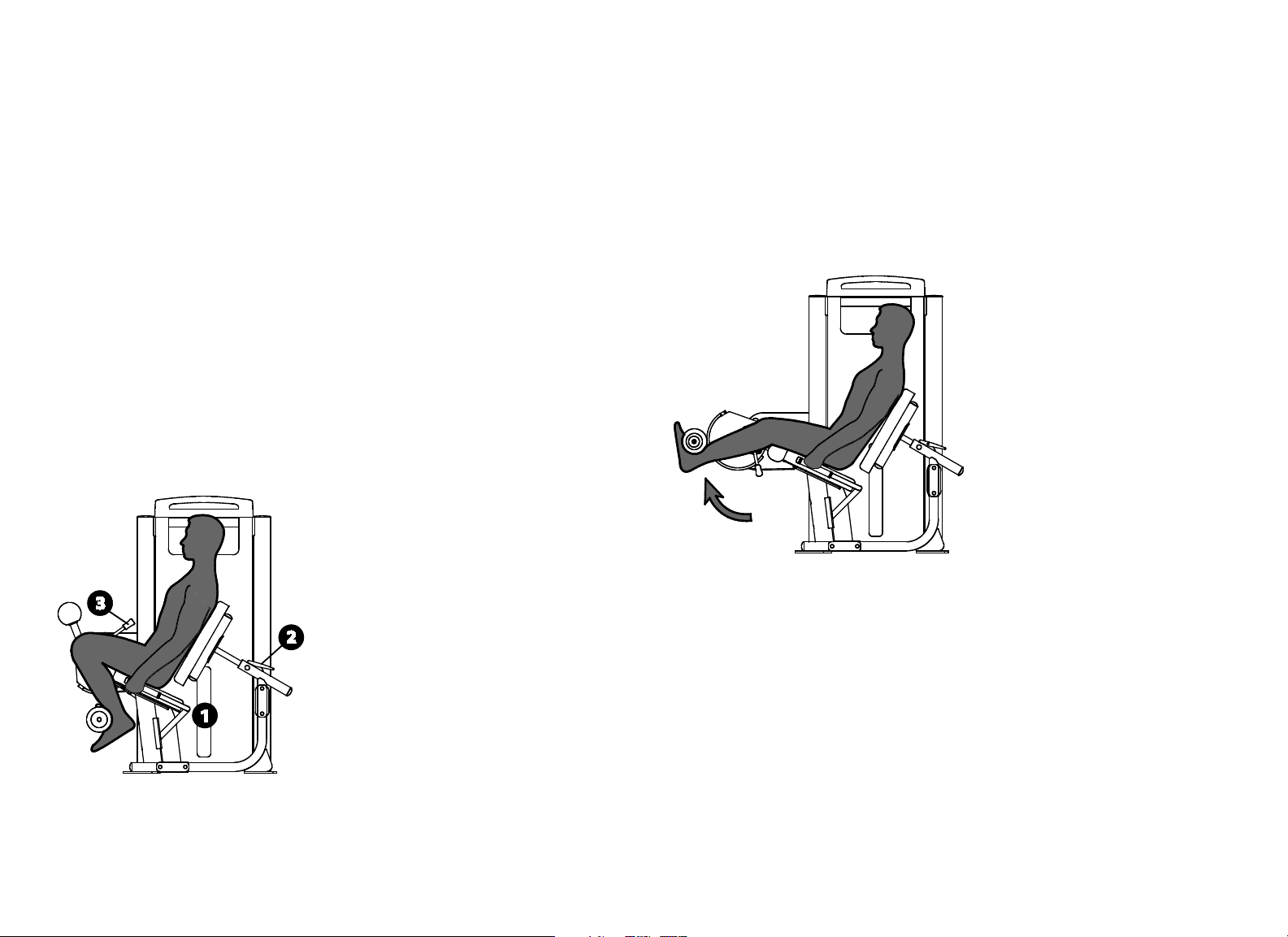
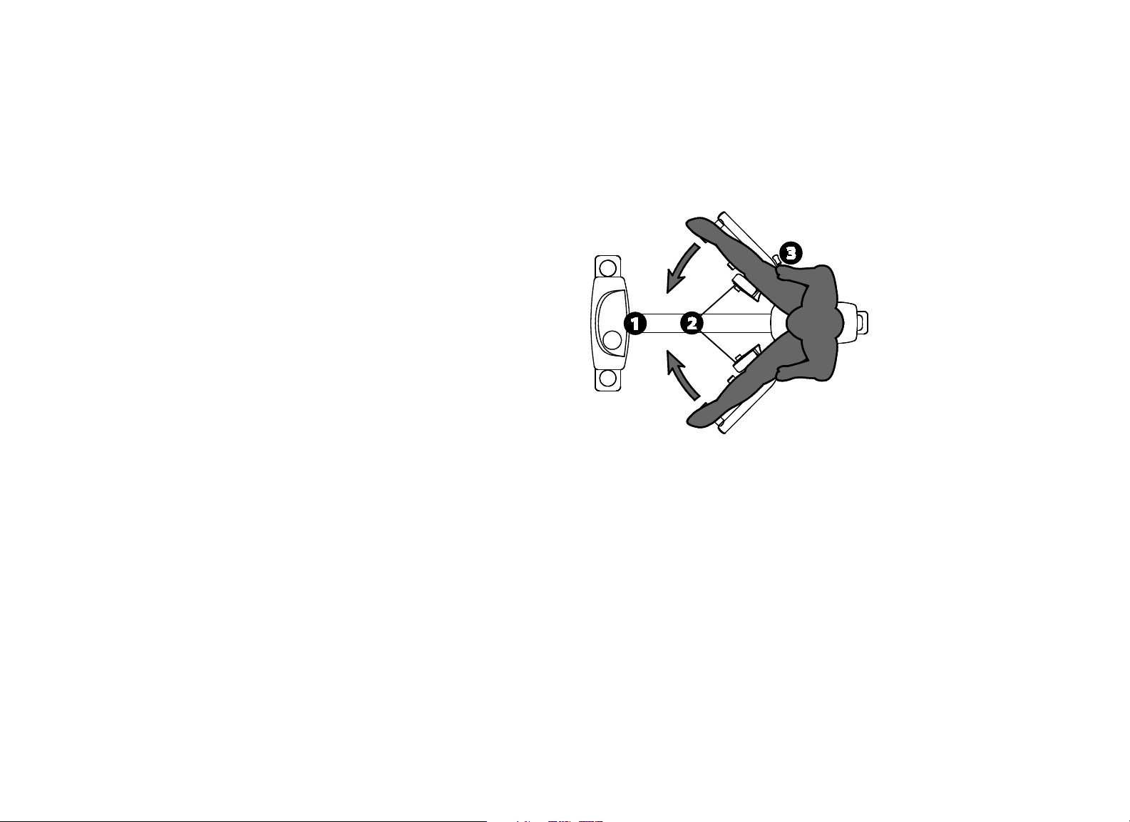
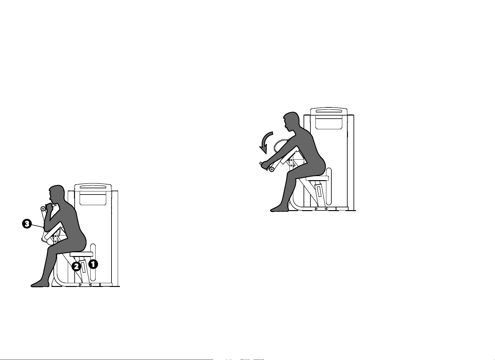
Leg Extension / Leg Curl
Specifications
Equipment
Dimensions
64" L x 43" W x 57" H (163 cm L x 109 cm W x 145
cm H)
Working Area 71" L x 43" W (180 cm L x 109 cm W)
Weight Stack 240 lb (110 kg)
Equipment Weight 530 lb (240 kg)
Setup
1. Select an appropriate weight.
2. Set the movement arm to position 1 and place your legs against the pads as
shown for the exercise.
3. Align your knees with the pivot by adjusting the back pad.
4. Adjust the ankle pad as shown for the exercise.
5. Set the movement arm to your desired start position.
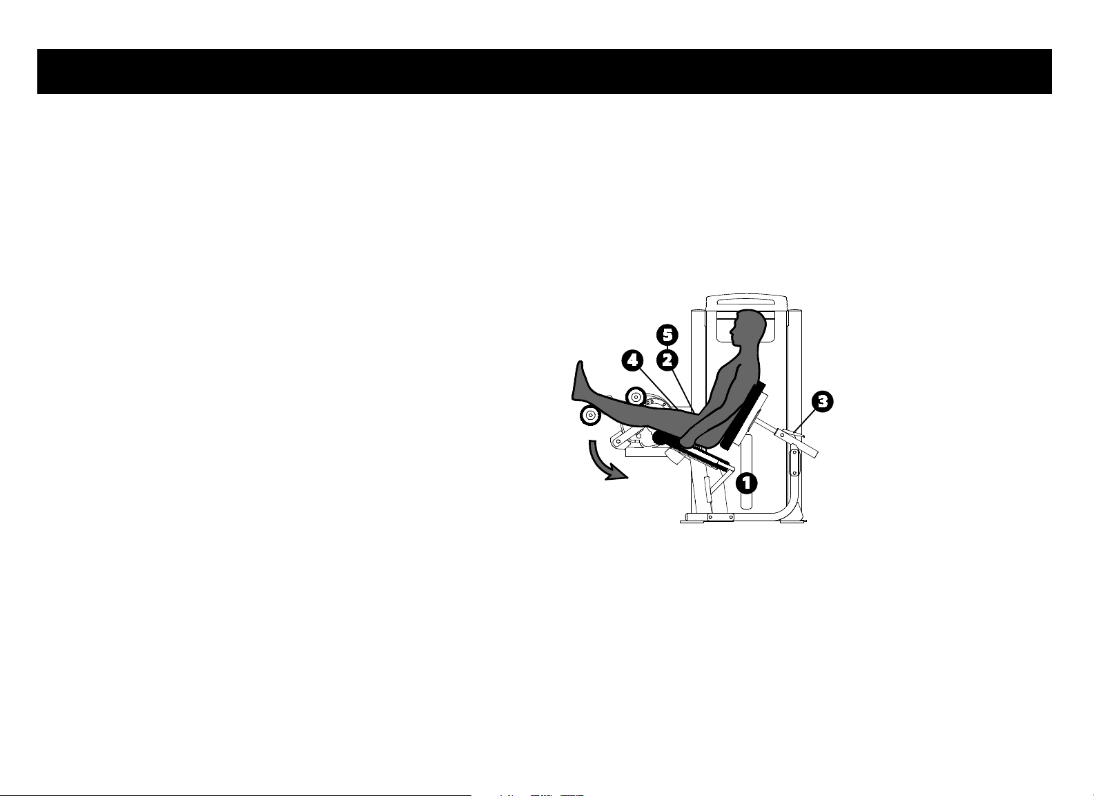
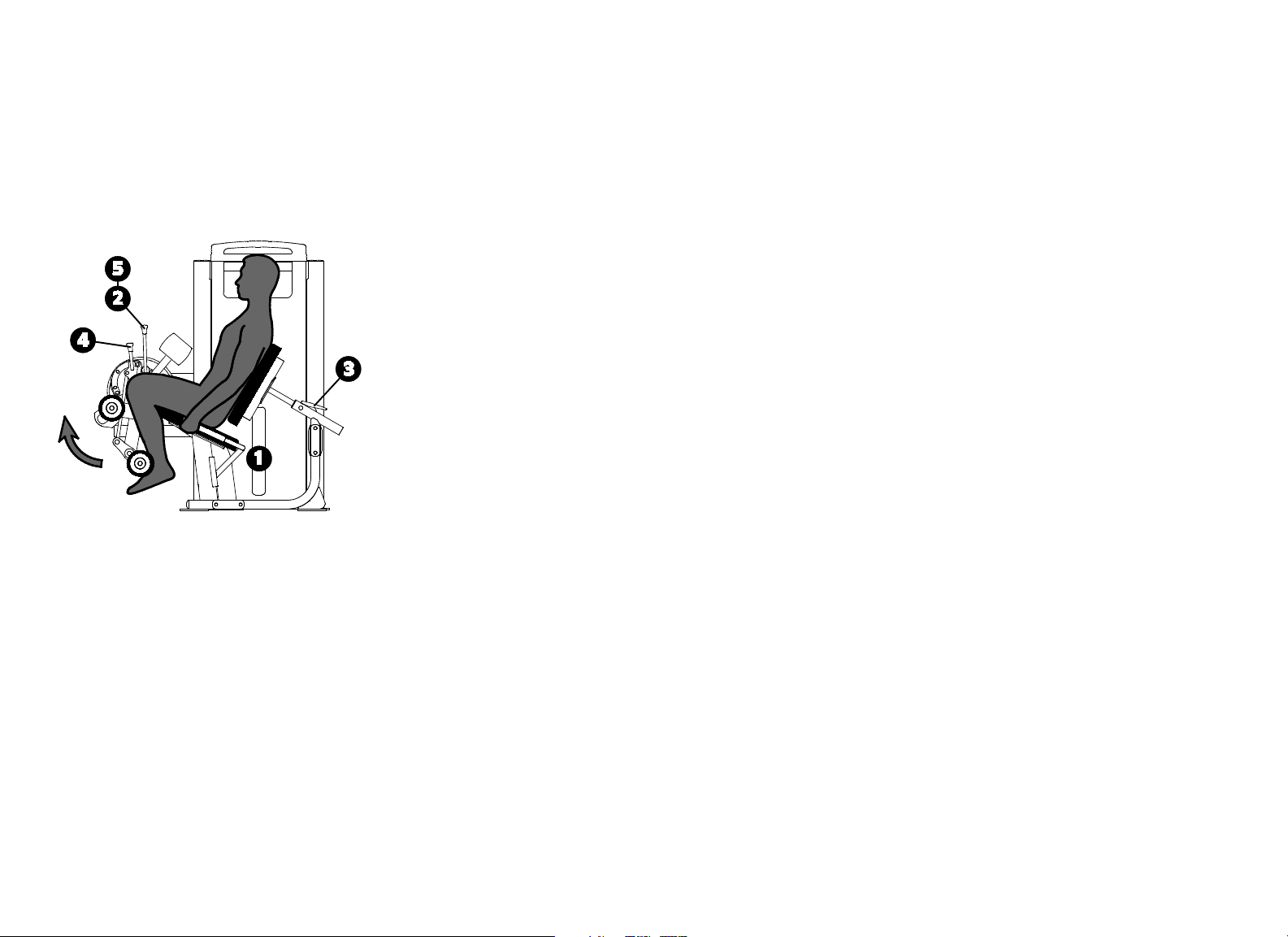
Exercise (Leg Curl)
Grasp both handles.
Curl your legs in a slow, controlled motion.
Pause at full contraction.
Slowly return to the start position.
Product Specifications and Use
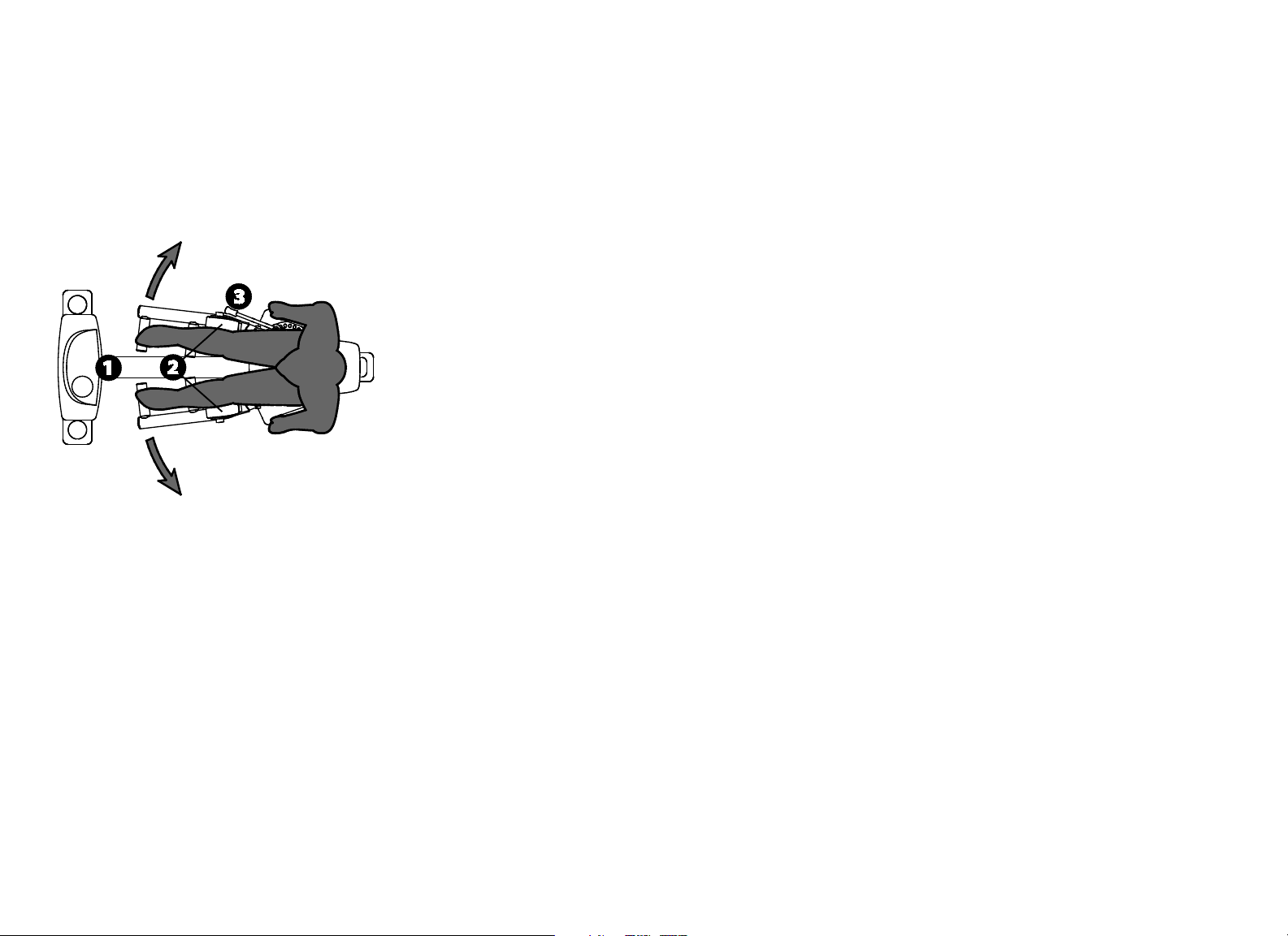
Vitality Series Selectorized Line Owner's Manual: Product Specifications and Use 6
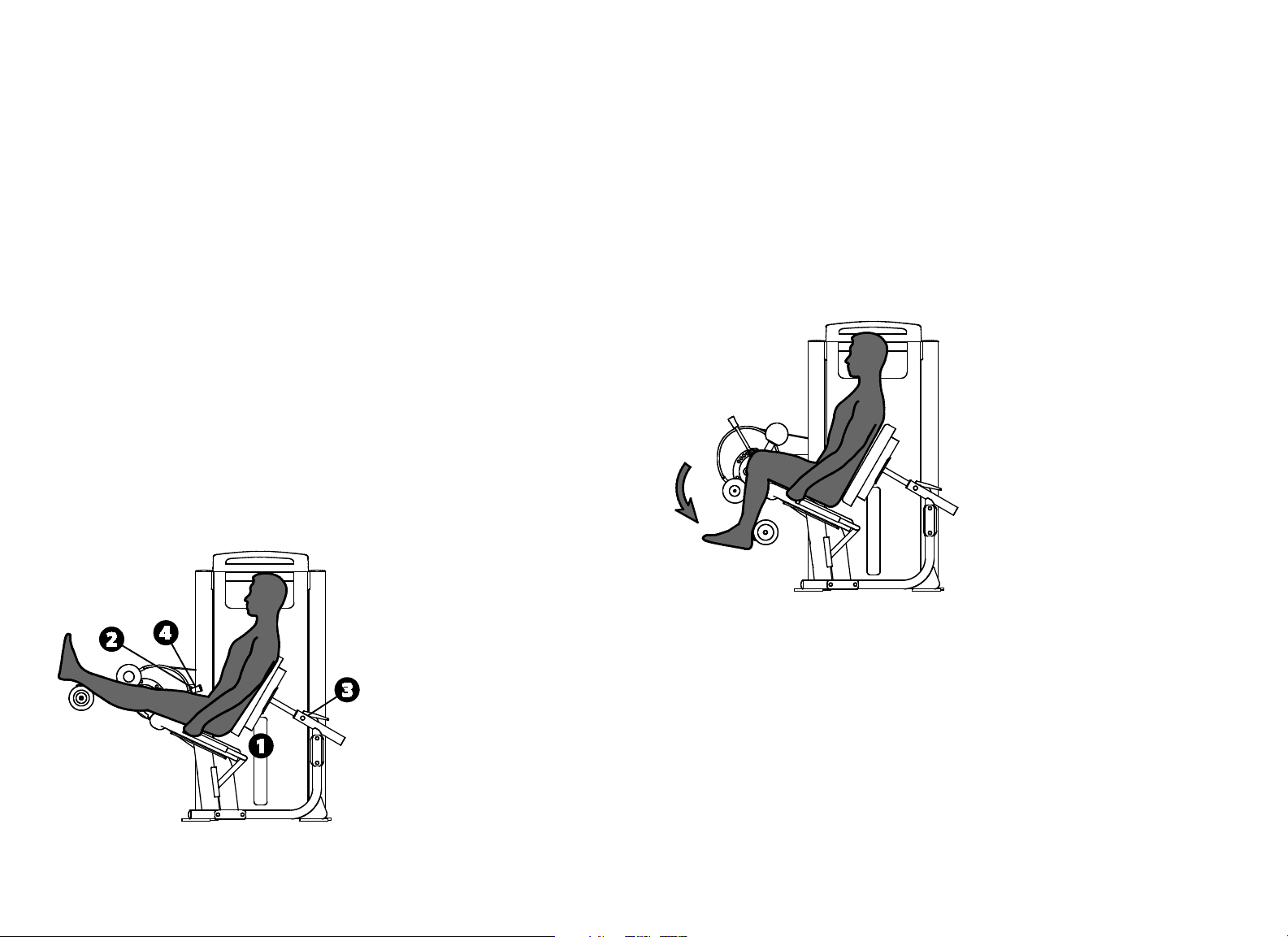
Exercise (Leg Extension)
Grasp both handles.
Extend your legs in a slow, controlled motion.
Pause at full extension.
Slowly return to the start position.
Training Tips
Lengthen your pause time at full contraction or extension.
Vitality Series Selectorized Line Owner's Manual: Product Specifications and Use 7
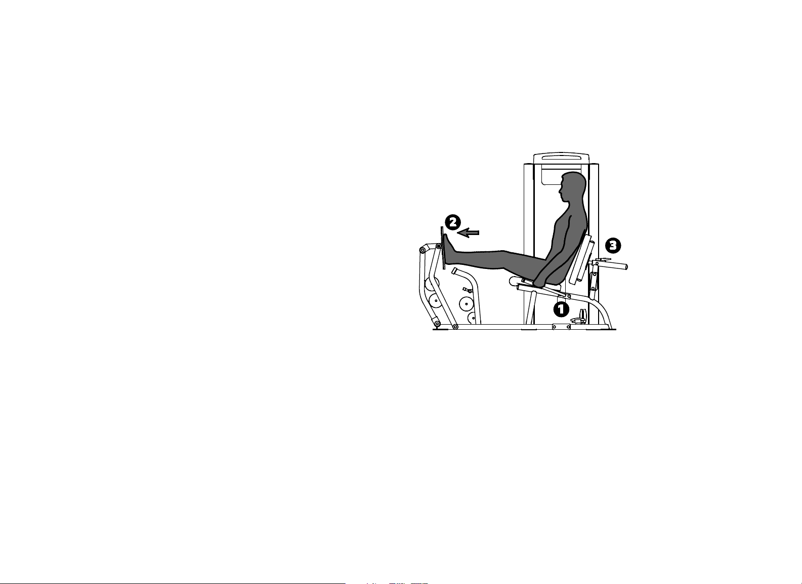
Leg Extension
Specifications
Equipment
Dimensions
52" L x 43" W x 57" H (132 cm L x 109 cm W x 145
cm H)
Working Area 69" L x 43" W (176 cm L x 109 cm W)
Weight Stack
Standard unit: 200 lb (91 kg)
IFI-accredited unit: 175 lb (80 kg)
Equipment Weight 462 lb (210 kg)
Setup
1. Select an appropriate weight.
2. Align your knees with the pivot by adjusting the back pad.
3. Set the movement arm to your desired start position.
Exercise
Grasp both handles.
Extend your legs in a slow, controlled motion.
Pause at full extension.
Slowly return to the start position.
Training Tips
Lengthen your pause time at full extension.
Vitality Series Selectorized Line Owner's Manual: Product Specifications and Use 8
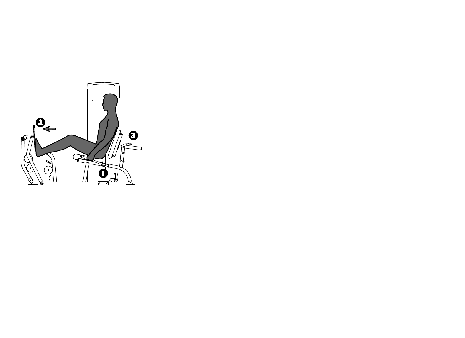
Seated Leg Curl
Specifications
Equipment
Dimensions
62" L x 43" W x 57" H (157 cm L x 109 cm W x 145
cm H)
Working Area 67" L x 43" W (171 cm L x 109 cm W)
Weight Stack
Standard unit: 170 lb (78 kg)
IFI-accredited unit: 145 lb (66 kg)
Equipment Weight 450 lb (205 kg)
Setup
1. Select an appropriate weight.
2. Set the movement arm to the “Ø” setup position, and place your legs
against the pads.
3. Align your knees with the pivot by adjusting the back pad.
4. Set the movement arm to your desired start position.
Exercise
Grasp both handles.
Curl your legs in a slow, controlled motion.
Pause at full contraction.
Slowly return to the start position.
To exit the equipment at the end of your exercise, set the movement arm
to the “Ø” Setup position.
Training Tips
Lengthen your pause time at full contraction.
Vitality Series Selectorized Line Owner's Manual: Product Specifications and Use 9
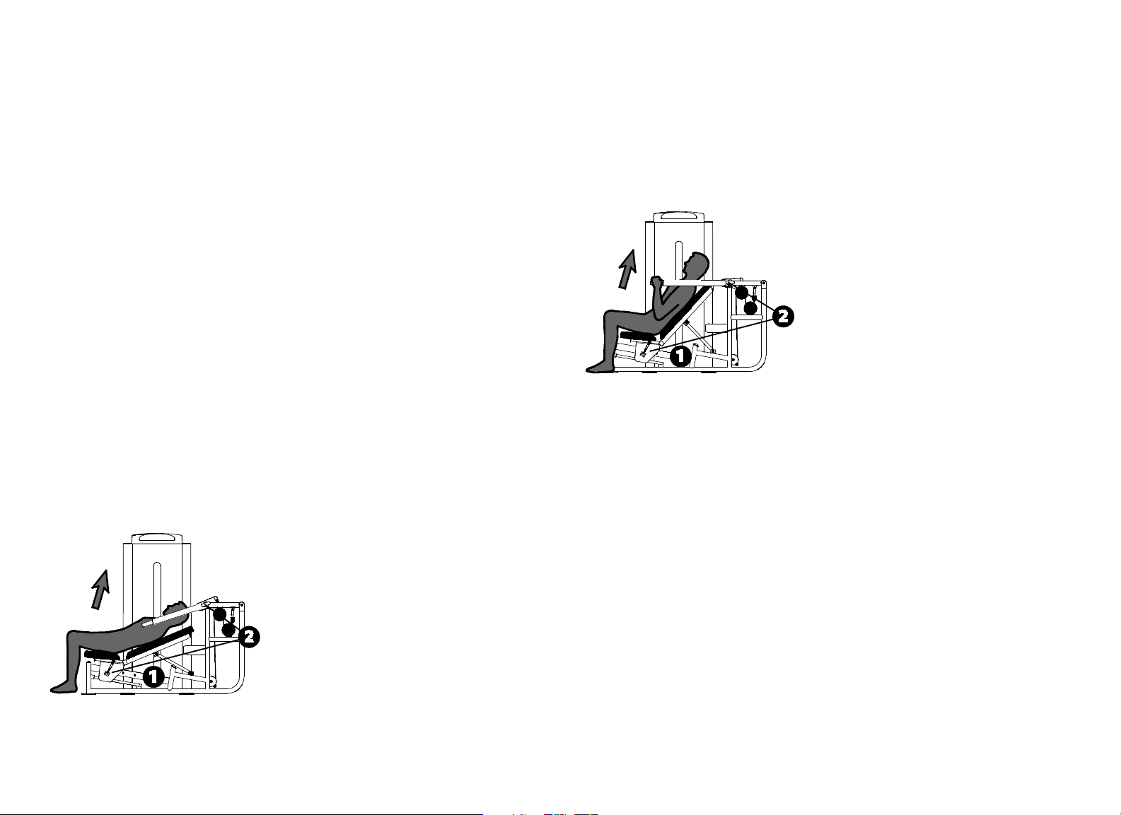
Leg Press / Calf Extension
Specifications
Equipment
Dimensions
76" L x 43" W x 69" H (193 cm L x 109 cm W x 175
cm H)
Working Area 82" L x 43" W (209 cm L x 109 cm W)
Weight Stack 295 lb (135 kg)
Equipment Weight 550 lb (250 kg)
Setup
1. Select an appropriate weight.
2. Sit and place your feet on the footplate approximately shoulder-width
apart (leg press) or with the balls of the feet at the bottom of the footplate
(calf raise).
3. Adjust the back pad so that your knee angle is at a 90° start position.
Exercise (Leg Press)
Extend your legs in a slow, controlled motion.
Pause at full extension.
Slowly return to the start position.
Vitality Series Selectorized Line Owner's Manual: Product Specifications and Use 10
Exercise (Calf Extension)
Push with your feet in a slow, controlled motion.
Pause at full extension.
Slowly return to the start position.
Training Tips
Avoid locking your knees.
For a full range of calf extension motion, start with your ankles flexed and
push to full extension.
Vitality Series Selectorized Line Owner's Manual: Product Specifications and Use 11
Inner / Outer Thigh
Specifications
Equipment
Dimensions
64" L x 31" W x 57" H (163 cm L x 79 cm W x 145
cm H)
Working Area 64" L x 69" W (163 cm L x 176 cm W)
Weight Stack 170 lb (78 kg)
Equipment Weight 440 lb (200 kg)
Setup
1. Select an appropriate weight.
2. Rotate pads to face outward (inner thigh) or to face each other (outer
thigh).
3. Set the movement arms to your desired start position.
Exercise (Inner Thigh)
Grasp both handles.
Squeeze thighs inward in a slow, controlled motion.
Pause at full contraction.
Slowly return to start position.
Vitality Series Selectorized Line Owner's Manual: Product Specifications and Use 12
Exercise (Outer Thigh)
Grasp both handles.
Push thighs outward in a slow, controlled motion.
Pause at full contraction.
Slowly return to start position.
Training Tips
Exercise through a full range of motion.
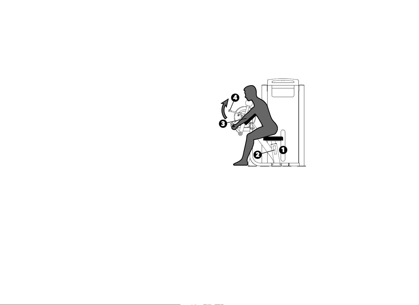
Vitality Series Selectorized Line Owner's Manual: Product Specifications and Use 13
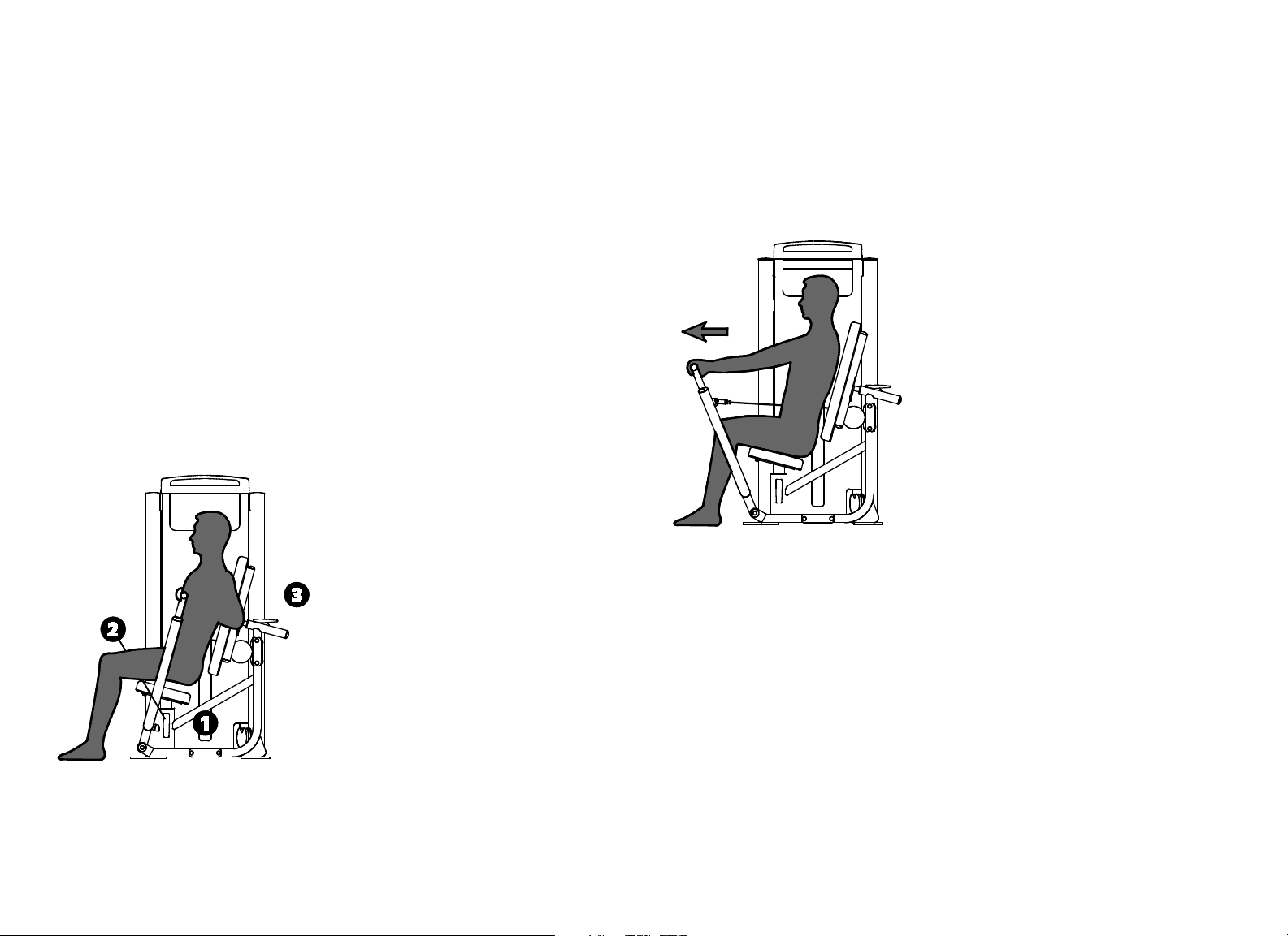
Biceps Curl / Triceps Extension
Specifications
Equipment
Dimensions
51" L x 43" W x 57" H (130 cm L x 110 cm W x 145
cm H)
Working Area 63" L x 43" W (160 cm L x 110 cm W)
Weight Stack 170 lb (78 kg)
Equipment Weight 395 lb (180 kg)
Setup
1. Select an appropriate weight.
2. Adjust the seat height so your upper arms rest flat on the pad.
3. Align your elbows with the pivot.
4. Set the movement arm to the desired start position.
Exercise (Biceps Curl)
Grasp both handles.
Curl your arms in a slow, controlled motion.
Pause at full contraction.
Slowly return to the start position.

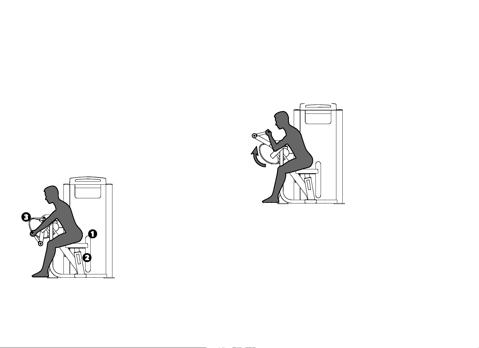
Vitality Series Selectorized Line Owner's Manual: Product Specifications and Use 14
Exercise (Triceps Extension)
Grasp both handles.
Extend your arms in a slow, controlled motion.
Pause at full extension.
Slowly return to the start position.
Training Tips
Keep your upper arms flat on the pad.
Lengthen your pause time at full contraction or extension.
Vitality Series Selectorized Line Owner's Manual: Product Specifications and Use 15
Biceps Curl
Specifications
Equipment
Dimensions
47" L x 40" W x 57" H (119 cm L x 102 cm W x 145
cm H)
Working Area 54" L x 40" W (137 cm L x 102 cm W)
Weight Stack 170 lb (78 kg)
Equipment Weight 395 lb (180 kg)
Setup
1. Select an appropriate weight.
2. Adjust the seat height so your upper arms rest flat on the pad.
3. Align your elbows with the pivot.
Exercise
Grasp both handles.
Curl your arms in a slow, controlled motion.
Pause at full contraction.
Slowly return to the start position.
Training Tips
Keep your upper arms flat on the pad.
Exercise through a full range of motion.
Vitality Series Selectorized Line Owner's Manual: Product Specifications and Use 16
Triceps Extension
Specifications
Equipment
Dimensions
46" L x 40" W x 57" H (117 cm L x 102 cm W x 145
cm H)
Working Area 70" L x 40" W (178 cm L x 102 cm W)
Weight Stack 170 lb (78 kg)
Equipment Weight 395 lb (180 kg)
Setup
1. Select an appropriate weight.
2. Adjust the seat height so your upper arms rest flat on the pad.
3. Align your elbows with the pivot.
Exercise
Grasp both handles.
Extend your arms in a slow, controlled motion.
Pause at full extension.
Slowly return to the start position.
Training Tips
Keep your upper arms flat on the pad.
Exercise through a full range of motion.
Vitality Series Selectorized Line Owner's Manual: Product Specifications and Use 17
Multi-Press
Specifications
Equipment
Dimensions
72" L x 60" W x 69" H (183 cm L x 152 cm W x 175
cm H)
Working Area 96" L x 60" W (244 cm L x 152 cm W)
Weight Stack 240 lb (110 kg)
Equipment Weight 450 lb (205 kg)
Setup
1. Select an appropriate weight.
2. Adjust the seat and movement arm to your desired start position.
Exercise (Chest Press)
Grasp both handles.
Extend your arms in a slow, controlled motion.
Pause at full extension.
Slowly return to the start position.
Exercise (Incline Press)
Grasp both handles.
Extend your arms in a slow, controlled motion.
Pause at full extension.
Slowly return to the start position.

Vitality Series Selectorized Line Owner's Manual: Product Specifications and Use 18
Exercise (Shoulder Press)
Grasp both handles.
Extend your arms in a slow, controlled motion.
Pause at full extension.
Slowly return to the start position.
Training Tips
Exercise through a full range of motion.
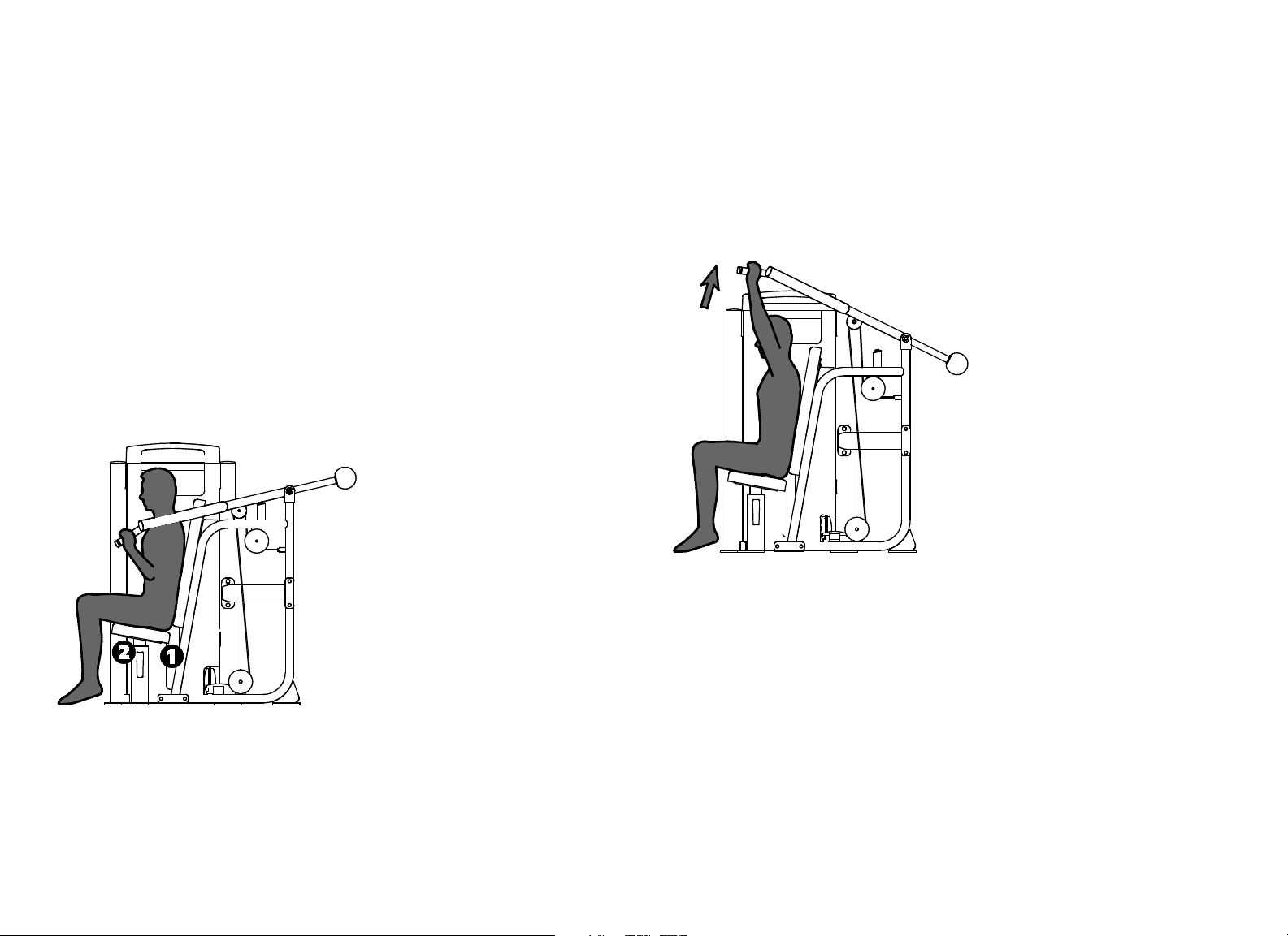
Vitality Series Selectorized Line Owner's Manual: Product Specifications and Use 19
Chest Press
Specifications
Equipment
Dimensions
39" L x 51" W x 69" H (99 cm L x 130 cm W x 175
cm H)
Working Area 65" L x 51" W (166 cm L x 130 cm W)
Weight Stack 240 lb (110 kg)
Equipment Weight 450 lb (205 kg)
Setup
1. Select an appropriate weight.
2. Adjust the seat so the handles are aligned with your mid-chest.
3. Adjust the back pad to your desired start position.
Exercise
Grasp both handles.
Extend your arms in a slow, controlled motion.
Pause at full extension.
Slowly return to the start position.
Training Tips
Avoid locking your elbows.
To vary your routine, use the vertical handles.
Vitality Series Selectorized Line Owner's Manual: Product Specifications and Use 20
Shoulder Press
Specifications
Equipment
Dimensions
59" L x 56" W x 57" H (150 cm L x 142 cm W x 145
cm H)
Working Area 62" L x 56" W (158 cm L x 142 cm W)
Weight Stack 200 lb (91 kg)
Equipment Weight 430 lb (195 kg)
Setup
1. Select an appropriate weight.
2. Adjust the seat height so the handles are slightly above your shoulders.
Exercise
Grasp both handles.
Extend your arms in a slow, controlled motion while keeping your back
firmly against the pad.
Pause at full extension.
Slowly return to the start position.
Training Tips
Avoid locking your elbows.
Vitality Series Selectorized Line Owner's Manual: Product Specifications and Use 21
Pulldown / Row
Specifications
Equipment
Dimensions
76" L x 48" W x 87" H (193 cm L x 122 cm W x 221
cm H)
Working Area 76" L x 59" W (193 cm L x 150 cm W)
Weight Stack 220 lb (100 kg)
Equipment Weight 490 lb (222 kg)
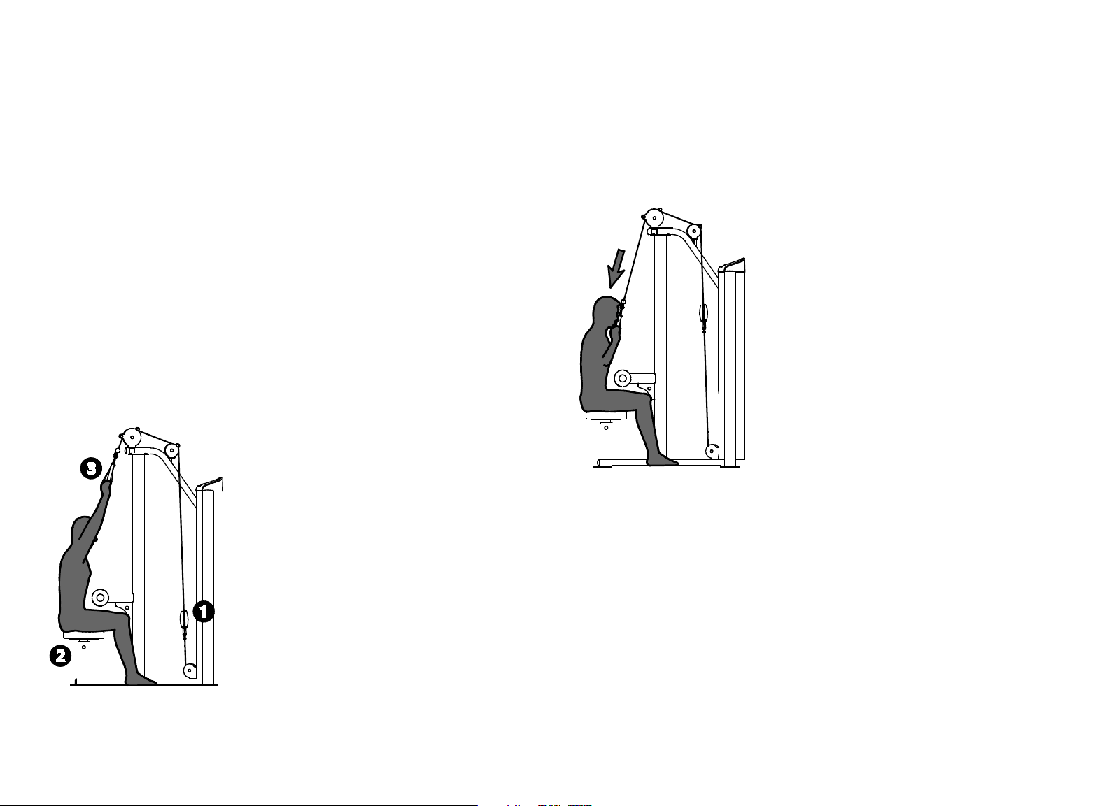
Setup
1. Select an appropriate weight.
2. For Pulldown, adjust the thigh pads to hold your legs securely in place.
Then stand, grasp the pulldown bar with both hands, and return to the
seated position.
3. For Row, sit back on the seat and place your feet on the foot pedals. Then
grasp the row handle with both hands and start with back in straight up
position.
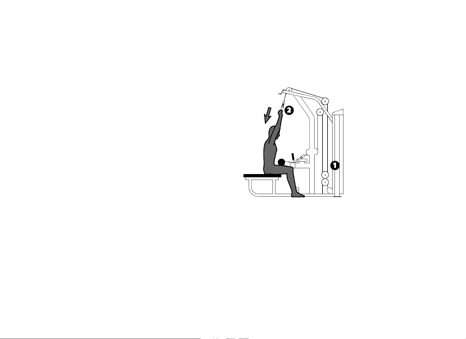
Exercise (Pulldown)
Begin with your arms extended, elbows slightly bent.
Pull the pulldown bar to chin level in a slow, controlled motion.
Pause at full contraction.
Slowly return to the start position.

Vitality Series Selectorized Line Owner's Manual: Product Specifications and Use 22
Exercise (Row)
Begin with your arms extended, elbows slightly bent.
Pull the row handle toward you in a slow, controlled motion.
Pause at full contraction.
Slowly return to the start position.
Training Tips
Avoid leaning back during exercise.
Vitality Series Selectorized Line Owner's Manual: Product Specifications and Use 23
Pulldown
Specifications
Equipment
Dimensions
40" L x 55" W x 85" H (102 cm L x 140 cm W x 216
cm H)
Working Area 76" L x 127" W (193 cm L x 323 cm W)
Weight Stack 220 lb (100 kg)
Equipment Weight 475 lb (215 kg)
Setup
1. Select an appropriate weight.
2. Adjust the seat so the thigh pads hold your legs securely in place.
3. Stand, grasp the handles with both hands, and return to the seated
position.
Exercise
Begin with your arms extended, elbows slightly bent.
Pull the handles to chin level in a slow, controlled motion.
Pause at full contraction.
Slowly return to the start position.
Training Tips
Avoid pulling the handles behind your neck.
Maintain good posture.
Vitality Series Selectorized Line Owner's Manual: Product Specifications and Use 24
Seated Row
Specifications
Equipment
Dimensions
50" L x 47" W x 69" H (127 cm L x 119 cm W x 175
cm H)
Working Area 50" L x 47" W (127 cm L x 119 cm W)
Weight Stack 240 lb (110 kg)
Equipment Weight 460 lb (210 kg)
Setup
1. Select an appropriate weight.
2. Adjust the seat so the chest pad is slightly below shoulder level.
3. Adjust the chest pad so your arms are fully extended.
Exercise
Grasp both handles.
Pull the handles toward you in a slow, controlled motion.
Pause at full contraction.
Slowly return to the start position.
Training Tips
Avoid leaning back during the exercise.
Vitality Series Selectorized Line Owner's Manual: Product Specifications and Use 25
Rear Delt / Pec Fly
Specifications
Equipment
Dimensions
40" L x 54" W x 78" H (102 cm L x 137 cm W x 198
cm H)
Working Area 40" L x 66" W (102 cm L x 168 cm W)
Weight Stack 240 lb (110 kg)
Equipment Weight 470 lb (214 kg)
Setup
1. Select an appropriate weight.
2. Face in (chest) or out (back) against the pad.
3. Rotate the handles to your desired start position.
4. Adjust the seat so the handles are at shoulder height.
Exercise (Pec Fly)
Grasp the vertical handles.
Pull the handles around in front of you in a slow, controlled motion.
Pause at full contraction.
Slowly return to the start position.

Vitality Series Selectorized Line Owner's Manual: Product Specifications and Use 26
Exercise (Rear Delt)
Grasp the horizontal handles.
Pull the handles around to the side of your body in a slow, controlled
motion.
Pause at full contraction.
Slowly return to the start position.
Training Tips
Keep your chest (Rear Delt) or back (Pec Fly) against the pad.
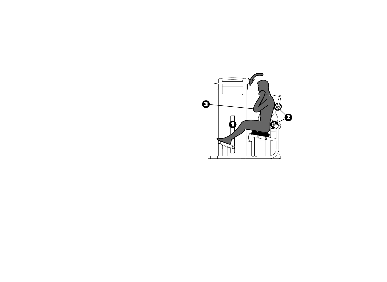
Vitality Series Selectorized Line Owner's Manual: Product Specifications and Use 27
Abdominal / Back Extension
Specifications
Equipment
Dimensions
59" L x 39" W x 57" H (150 cm L x 99 cm W x 145
cm H)
Working Area 63" L x 39" W (147 cm L x 99 cm W)
Weight Stack 200 lb (91 kg)
Equipment Weight 465 lb (210 kg)
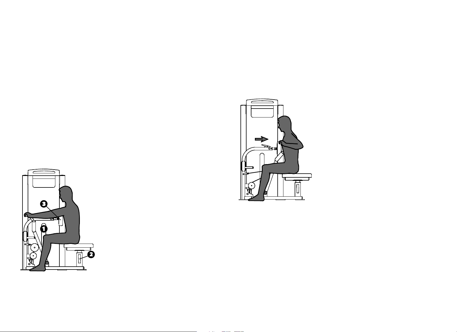
Setup
1. Select an appropriate weight.
2. Sit with your lower back against the roller pad and move the padded straps
to your upper chest.
3. Set the movement arm to the desired start position as shown.
Exercise (Abdominal)
Grasp both handles in front of your shoulders.
Curl down in a slow, controlled motion.
Pause at full contraction.
Slowly return to the start position.
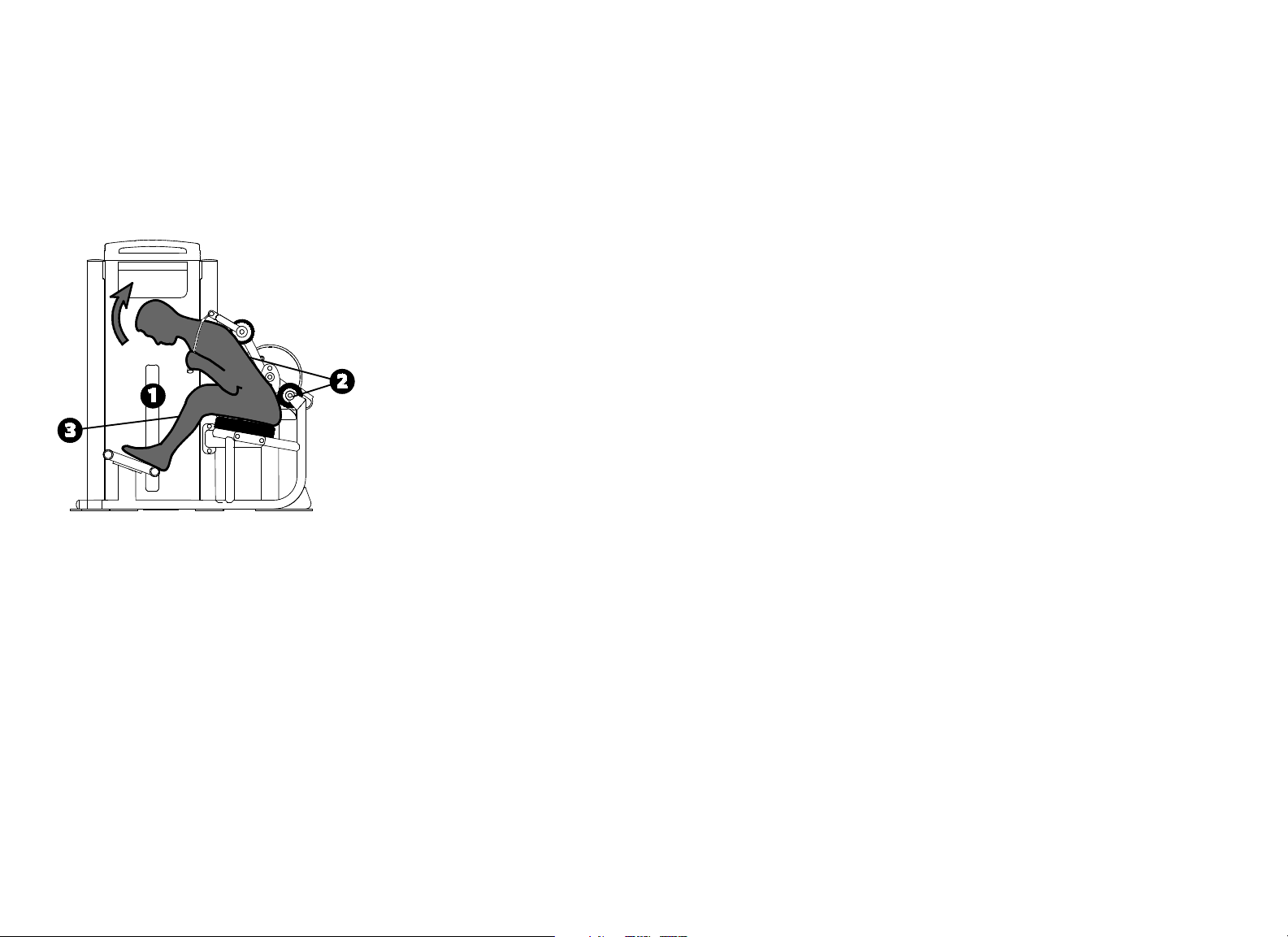
Vitality Series Selectorized Line Owner's Manual: Product Specifications and Use 28
Exercise (Back Extension)
Grasp both handles in front of your shoulders.
Extend backwards in a slow, controlled motion.
Pause at full extension.
Slowly return to the start position.
Training Tips
Use your arms only to stabilize the pads on your shoulders.
Avoid overextending your back.
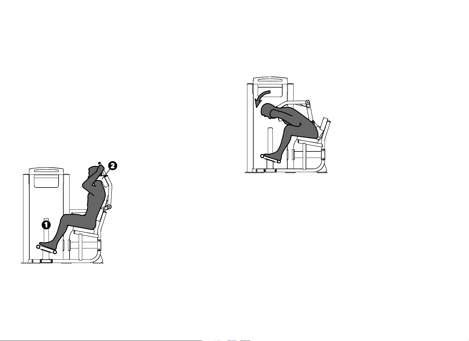
Vitality Series Selectorized Line Owner's Manual: Product Specifications and Use 29
Abdominal
Specifications
Equipment
Dimensions
58" L x 39" W x 57" H (147 cm L x 99 cm W x 145
cm H)
Working Area 58" L x 39" W (147 cm L x 99 cm W)
Weight Stack 200 lb (91 kg)
Equipment Weight 465 lb (210 kg)
Setup
1. Select an appropriate weight.
2. Sit, grasp the handles, and pull the pads until they rest on your shoulders.
Exercise
Curl down in a slow, controlled motion.
Pause at full contraction.
Slowly return to the start position.
Training Tips
Use your arms only to stabilize the pads on your shoulders.
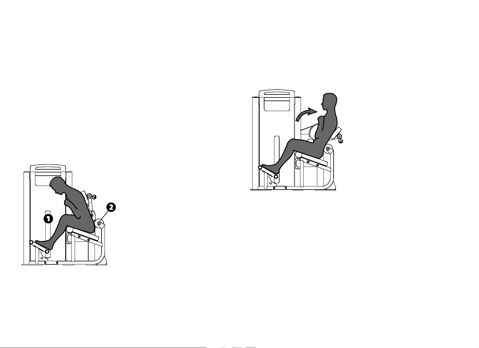
Vitality Series Selectorized Line Owner's Manual: Product Specifications and Use 30
Back Extension
Specifications
Equipment
Dimensions
53" L x 39" W x 57" H (135 cm L x 99 cm W x 145
cm H)
Working Area 53" L x 39" W (150 cm L x 99 cm H)
Weight Stack 200 lb (91 kg)
Equipment Weight 450 lb (205 kg)
Setup
1. Select an appropriate weight.
2. Sit into the seat until your lower back rests against the back roller pad.
Exercise
Cross your arms in front of your chest.
Extend back in a slow, controlled motion.
Pause at full extension.
Slowly return to the start position.
Training Tips
Keep your lower back against the roller pad.
Avoid overextending.

Vitality Series Selectorized Line Owner's Manual: Maintenance 31
Before You Begin
Precor recommends implementing a thorough maintenance program that
incorporates regular safety inspections by qualified maintenance technicians
as outlined in this manual.
This manual explains how to maintain the Vitality™ Series Selectorized Line of
commercial strength equipment. It provides information about items that need
to be inspected and maintained on a daily, weekly, monthly, and annual basis.
You should perform those tasks that are appropriate for the equipment you are
maintaining, and skip those tasks that do not apply.
This manual covers the general maintenance procedures that you can perform
in the fitness facility. However, if the equipment requires service beyond the
maintenance procedures covered in this manual, refer to Obtaining Service.
Important: Always purchase replacement parts and hardware from Precor. Many
parts are tested and manufactured specifically for Precor commercial strength
equipment. If you use parts not approved by Precor, you could void the Precor
Limited Warranty. Use of parts not approved by Precor may cause injury.
Precor recommends that maintenance technicians thoroughly read and
understand the safety guidelines and maintenance procedures covered in this
manual.
Note: If the equipment requires assembly, a separate assembly guide is
provided. For information on how to use a piece of equipment, refer to the
instructional label found on the equipment and the Product Specifications and
Use section in this manual.
Recommended Tools
We recommend that you keep the following tools available to inspect and
maintain the equipment:
Complete combination box wrench set (common metric sizes)
Complete socket set (common metric and SAE sizes)
Complete hex key set (common metric sizes)
12-inch adjustable wrench
Rubber mallet
Maintenance
Vitality Series Selectorized Line Owner's Manual: Maintenance 32
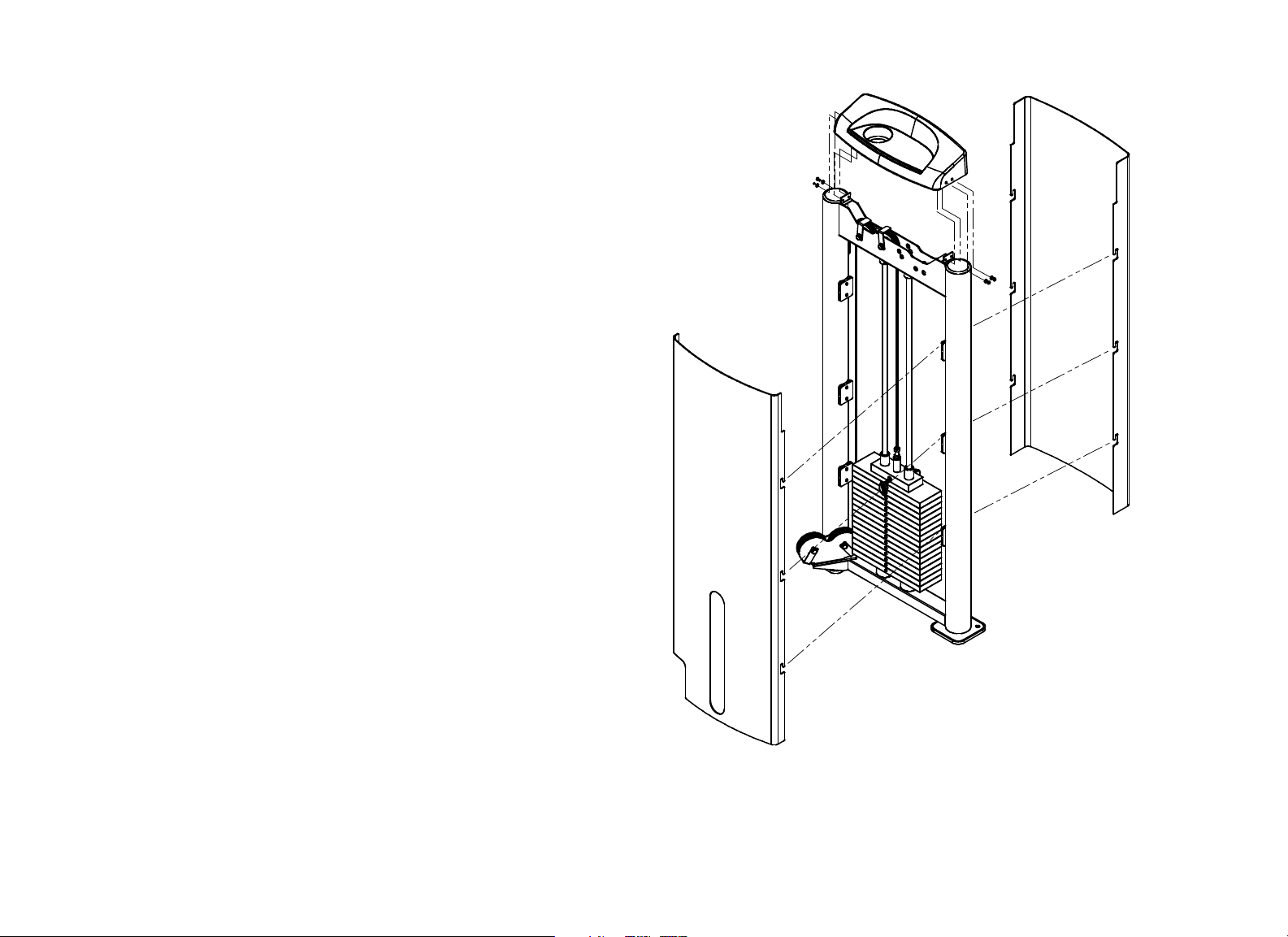
Shroud Removal
The Vitality™ Series Selectorized Line includes a shroud that must be removed
to perform the maintenance described in this manual.
Important: Do not remove the shroud while the equipment is in use.
Use the following instructions to remove the shroud:
1. Remove the four M6 * 12 mm buttonhead screws that secure the top cap
to the weight tower frame. Set the screws aside, taking care to keep the
four 7 mm flat washers with them.
2. Lift the outside shroud straight up until its tabs are clear of the shroud clips
mounted on the weight tower uprights, then remove the outside shroud.
3. Repeat the previous step to remove the inside shroud.
Perform the necessary maintenance. When you are finished, replace the
shroud.
4. Align the tabs on both sides of the inside shroud with the slots on the
shroud clips, as shown in the following figure.
5. Press the edges of the shroud in, then down, to secure the shroud.
6. Repeat the previous two steps to mount the outside shroud on the unit.
Important: Just inside the lip of the top cap are ribs that align the top cap with
the outside and inside shrouds. In the following step, make sure that the top
edges of the two shroud panels fit between these ribs and the lip of the top cap.
7. Slide the top cap over the top edges of the two shrouds, making sure that
the top edges of the shrouds align correctly with the top cap.
8. Secure the top cap to the weight tower frame using the buttonhead screws
and flat washers you removed earlier.
9. Wrench-tighten all four screws.
Figure 1: Shroud detail

Vitality Series Selectorized Line Owner's Manual: Maintenance 33
Daily Inspection
You will need to perform the following tasks each day to maintain the
equipment and keep it operating smoothly:
Clean upholstery.
Clean shrouds.
Inspect pads for wear.
Clean and inspect frames.
Inspect all fasteners.
Inspect cables and end connections.
Check warning and instructional labels.
Perform the tasks that are appropriate for the equipment you are maintaining,
and skip the tasks that do not apply.
Clean Upholstery
To remove surface dirt and perspiration, clean upholstery daily with a mild
soap and water solution in a spray bottle. Spray upholstered surfaces lightly
and wipe dry with a clean cloth.
Important: To clean the upholstery, do not use cleaning products that have any of
these ingredients: solvents, alcohol, ammonia, or petroleum. Use a mild detergent-
based cleaner instead.
Inspect Pads for Wear
Inspect pads for cracks in the upholstery, broken and loose stitching, loose
staples, and loose mounting bolts. Replace pads as needed (refer to Obtaining
Service to purchase new pads).
Important: Do not reupholster pads or use pads not approved by Precor.
Clean and Inspect Frames
To remove grease and dirt, clean frames daily with a mild soap and water
solution in a spray bottle. Wipe the equipment down with a damp cloth and
dry completely. Be sure to wipe down both painted parts and chrome or plated
parts.
To restore and maintain the luster of chrome parts, use a commercial chrome
cleaner.
As you clean, inspect the frames for cracks, rust, or other damage. Make sure
welds are solid and fasteners are properly secured.

Vitality Series Selectorized Line Owner's Manual: Maintenance 34
Inspect Cables and End Connections
CAUTION: Carefully inspect the cables, pulleys, fasteners, and related
hardware regularly. Replace any cable at the first sign of wear using only
Precor-supplied replacement parts. With regular use, a cable can become
worn and might fail. Sudden failure of a worn cable can cause severe injury
to a user. Refer to Obtaining Service to purchase replacement parts.
Inspect the cables and end connections each day, and replace if damaged.
Check for kinks, frayed wires, or deterioration of the cable coating. Look for
signs of wear particularly at crimped ends of the cable and near pulleys.
Important: Cables must be replaced immediately if they are damaged to avoid
possible injury to users.
Some obvious signs of cable damage are as follows:
Exposed inner wire, stretching or cuts in the coating, or broken
coating in the area that passes over a pulley
A zigzag or wavy pattern
Kinks, which may indicate internal damage
A necked-down cover
A “ballooned” cover
Figure 2: Signs of cable damage
In addition to inspecting the cables and end connections for damage, check the
following:
Make sure that each cable is properly adjusted and tightened at the top of
the weight stack.
Check cable pulleys, end connections, and end fittings. Make sure all
connections are tight, adjusting cable tension as necessary.
Vitality Series Selectorized Line Owner's Manual: Maintenance 35
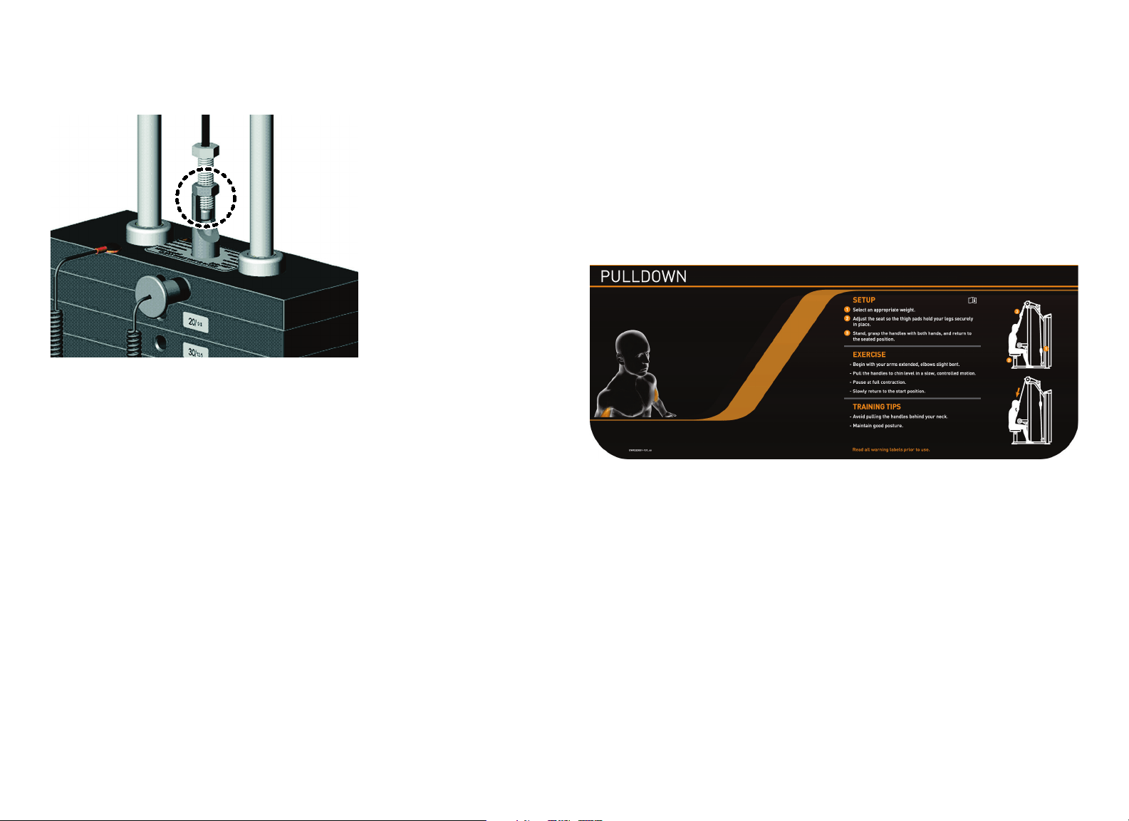
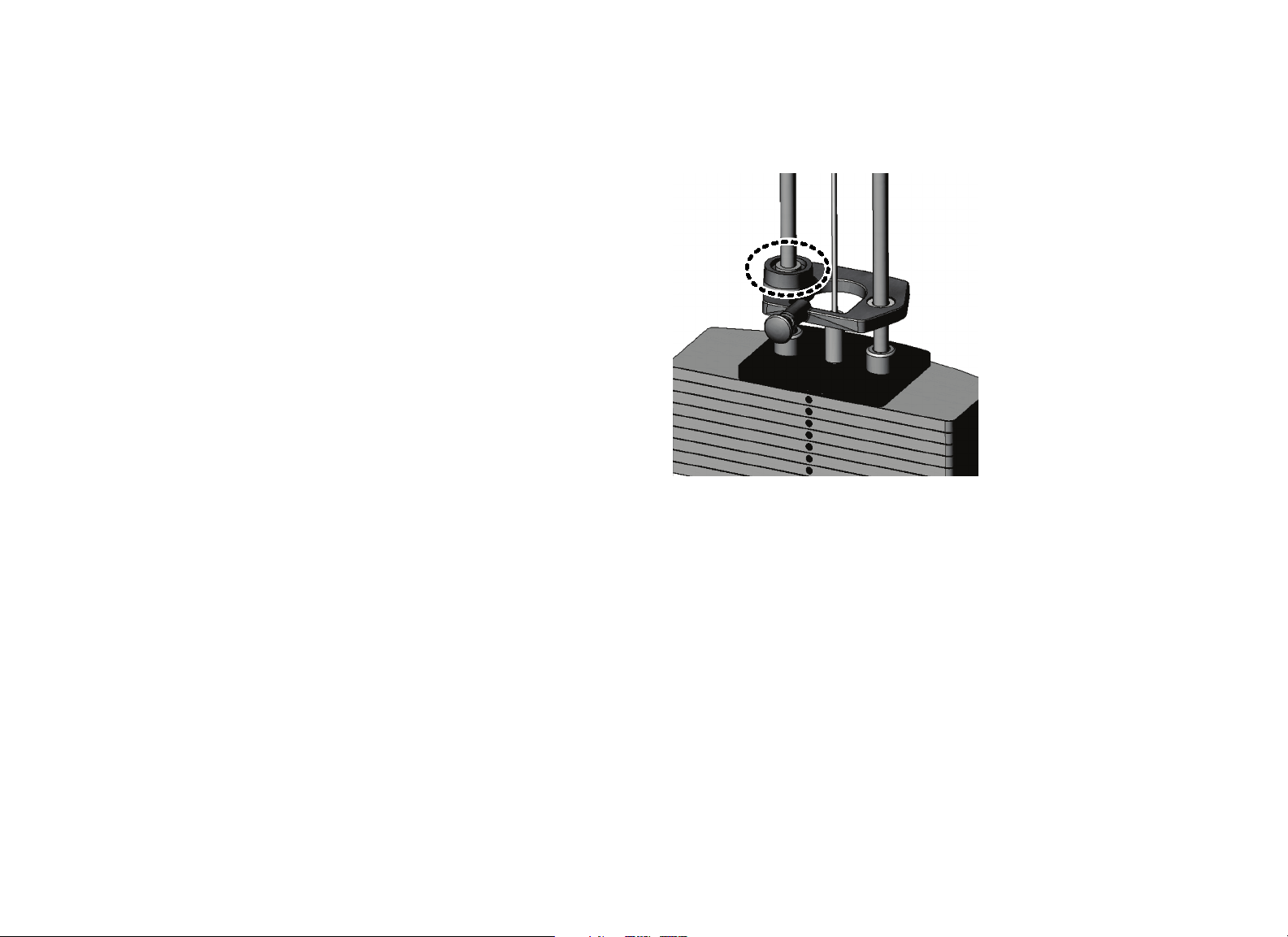
Make sure that the cable bolt is threaded a minimum of seven threads into
the selector stem, and the locking jam nut is tight. (Refer to the following
figure.)
Figure 3: Cable bolt must extend a minimum of seven threads into the selector
stem
Check Warning and Instructional Labels
Inspect warning and instructional labels daily to make sure that all the
information can be clearly read. If any portion is not visible or part of the label
is not adhered properly, replace that label immediately (refer to Obtaining
Service for purchase information).
Clean labels as needed with a mild soap and water solution in a spray bottle,
and dry thoroughly with a soft cloth.
The following figure shows an example of a user instructional label.
Figure 4: Example instructional label for the Vitality™ Series Selectorized Line
Vitality Series Selectorized Line Owner's Manual: Maintenance 36
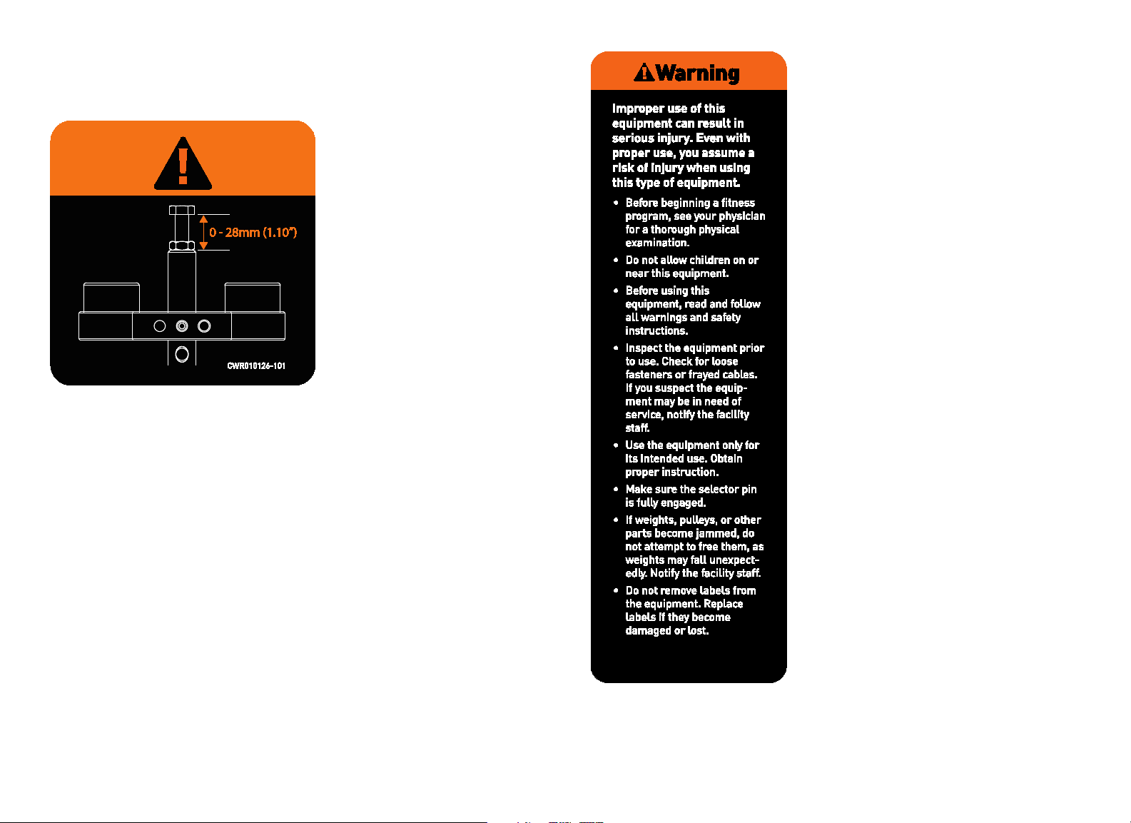
Precor products come equipped with a number of standard warning labels. The
following two figures show sample warning labels you may see on the
equipment depending on the model and product line:
Figure 5: A warning label may appear on or near weight stacks where a cable
bolt is threaded into the selector stem
Figure 6: A version of this warning label appears on the equipment frame

Vitality Series Selectorized Line Owner's Manual: Maintenance 37
Weekly Inspection
This section covers the tasks you should perform each week to maintain the
equipment. Perform the following tasks as appropriate for the unit you are
maintaining:
Condition and deep clean upholstery.
Clean and lubricate guide rods.
Inspect cables, connections, and tension.
Inspect pulleys.
Inspect each weight stack and selector pin.
Inspect and lubricate bearings and bushings.
Check and lubricate seat adjustment
Condition and Deep Clean Upholstery
Condition and deep clean the upholstery weekly with a lanolin-based hand
cleaner or upholstery cleaner.
Important: To clean the upholstery, do not use cleaning products that have
any of these ingredients: solvents, alcohol, ammonia, or petroleum. Use a mild
detergent-based cleaner instead.
Clean and Lubricate Guide Rods
Inspect the exposed areas of the guide rods for cleanliness. Using a dry cloth,
wipe any buildup of dirt or grease from the rods.
Note: On the Vitality™ Series Selectorized Line, the upper rear shroud must be
removed to access the guide rods for inspection, cleaning, and lubricating
(refer to Shroud Removal).
Lubricate the exposed areas of the guide rods by applying a light coat of
Teflon
®
spray lubricant. Spray the lubricant on a cloth and then wipe the guide
rods with the cloth. Be careful with any lubricant spray; it can stain carpet and
clothing.
CAUTION: Do not attempt to lubricate the guide rods when the equipment
is in use. Attempting to lubricate between the weight plates without
completely disassembling the stack will result in serious injury.
Important: Do not use petroleum-based lubricants. These lubricants tend to cause
a rapid buildup of dirt and hair on the weight plates, which can cause the plates to
stick together.
Vitality Series Selectorized Line Owner's Manual: Maintenance 38
Inspect Cables, Connections, and Tension
Each week, give the cables and connections a thorough inspection and check
cable tensions. The following lists the specific things you need to inspect:
Check the cable termination at the weight stack. For most equipment, the
exposed shank can be no more than 1¼ inches (32mm); this distance
allows for a minimum of 10 turns of the bolt into the selector stem (refer
to Inspect Cables and End Connections, earlier). Check and adjust the
distance accordingly. Also make sure that the locking jam nut is tight against
the selector stem.
Check the cable, especially near all pulley wheels and cams.
Check the cable as it terminates at the cam, which is stationary on most
equipment. Inspect the bolt passing through the cam end fitting to be sure
the two jam nuts are tightened against each other. Also, check the entire
cable routing to verify that there is no interference with any structure.
Inspect the ball end of the cable where the cable connection rests in the
clevis housing.
Make sure that each cable is properly adjusted and tightened at the top of
the weight stack.
Check cable pulleys, end connections, and end fittings. Make sure all
connections are tight, adjusting cable tension as necessary.
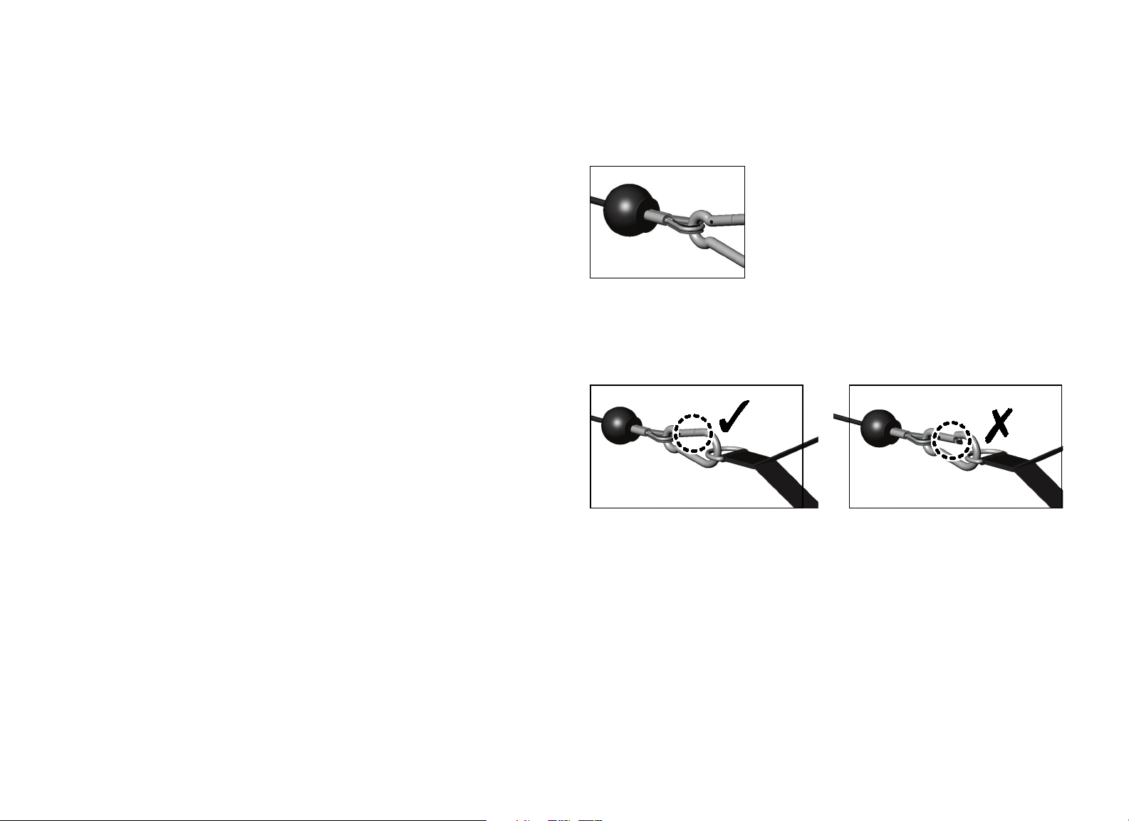
Inspect Cable Handle Attachments
Check the cable-to-handle attachment area very closely. (Refer to the
following figure.) Look for frayed cable ends, broken thimbles, bent cables,
worn spring clips, worn handles, and any other unusual wear.
Figure 7: Check connections to handles carefully
Also, check the spring clip gate and make sure it closes properly and engages
securely. (Refer to the following figure.) Check the spring clip, links, and cable;
replace any spring clip link that does not function properly or shows wear.
Figure 8: Check spring clip gate for proper closure

Vitality Series Selectorized Line Owner's Manual: Maintenance 39
Inspect Pulleys
Precor uses precision ball bearing idler pulleys to guide the cable smoothly.
Inspect each pulley for damage, including hairline cracks, chips, or missing
sections. Worn surfaces in the pulleys can cause severe damage to the cables
and must be replaced at the first sign of wear or damage.
Be certain that the wheels turn freely as the equipment is used. Inspect each
pulley for excessive side-to-side play, which indicates worn bearings or loose
mounting bolts. If excessive play is discovered, remove the pulley to inspect
the bearings and replace the entire pulley if necessary.
Inspect Weight Stack and Selector Pin
Weight stacks are made of precision machined plates that are designed as a
single mechanism to stack precisely. Use only Precor-supplied add-on weights
and weight selector pins.
On a weekly basis, inspect weight stacks and selector pins. Wipe each plate
with a damp cloth as needed. Inspect all plates for sharp burrs or damage.
Wipe dirt and dust off the guide rods.
Make sure the equipment uses only the original Precor selector pin. In
addition, make sure the selector pin can be fully inserted and retained in each
weight plate.
Vitality Series Selectorized Line Owner's Manual: Maintenance 40
Inspect and Lubricate Bearings and Bushings
Precor uses high quality bearings designed for strength applications and long
service life. Each week, do the following to maintain the bearings and bushings
on the equipment:
Bronze bushings: Precor recommends using a small amount of silicone
spray lubricant to lubricate these bushings, which usually support rotary
shafts. Spray directly onto the shaft, and then rotate the shaft through its
complete range of motion several times. Inspect bushings for excessive
wear and damage. Be careful when using the spray lubricant; it can stain
carpet and clothing. Wipe off any excess lubricant with a cloth.
Nylon bushings: Lubricate the nylon bushings on the guide rods by
applying a light coat of silicone spray lubricant. Spray the silicone lubricant
on a cloth, then wipe the cloth along the full length of the guide rod.
Sealed Bearing Pivot Points: These locations are protected from the
outside environment and require no lubrication. While cleaning the
equipment, wipe down the shafts and external bearing surfaces with a
cloth to prevent the buildup of dust and perspiration.
Linear Bearings: These bearings allow weight plates and other mechanical
parts to travel smoothly along guide rods. (Refer to the following figure.)
Inspect the ends of each guide rod to make sure they are fastened
correctly and all bolts are tight.
Wipe down guide rods using a light application of a silicone spray lubricant
to remove dust, hair, and dirt. Polish the guide rods using fine grade steel
wool if surface rust is present.
Important: Do not use petroleum-based lubricants.
If you lubricate the guide rods regularly, then the bearings will function as
designed. Otherwise, the guide rods may corrode. This can cause the bearings to
become clogged and jammed, leading to actual gouging of the guide rods. Be
sure to remove surface rust and oxidation from the guide rods as soon as you
observe it.
Figure 9: Typical location of a linear bearing in its housing

Vitality Series Selectorized Line Owner's Manual: Maintenance 41
Check Seat Adjustment and Test Pop Pins
Precor strength equipment has three types of adjustments:
2x4-inch or 2x2-inch telescoping sleeve adjustment for most seat
assemblies with and without ratcheting mechanism
¹⁄₂-inch slotted plate adjustments used on most free-weight bench
adjustments
Gas-assisted or spring-assisted seats and back pads
Inspect all adjustments for proper fit and function. Inspect plastic sliders for
excessive wear or damage. Check and clean the rail or gas shock periodically.
Adjustments use either a high-tensile pop pin plunger assembly or a ratcheting
lever assembly. Inspect and tighten all pop pin caps.
Monthly Inspection
This section covers the tasks you should perform each month to maintain the
equipment. Perform the following tasks as appropriate for the unit you are
maintaining:
Inspect frames and movement arms.
Lubricate pop pins.
Inspect Frames and Movement Arms
Inspect frames and movement arms monthly for proper function and integrity.
Check for cracks, chipped paint, or rust. Touch up dings and chips in the paint
as needed. Replace any component at first signs of wear.
Note: You can order touch-up paint from Precor by calling Customer Support.
Refer to Obtaining Service.
Inspect frames for cracks, particularly at the joints. If any cracks are found,
take the equipment out of service immediately and have a qualified
maintenance technician repair it. Refer to Important Safety Guidelines for
Owners and Obtaining Service.
To remove surface rust from the frame, rub lightly with a fine wet/dry
sandpaper or fine steel wool. Finish with Precor touch-up paint if needed.
Maintain paint luster with an application of a mild automotive wax product.
To maintain the powder coated, plated, and chrome parts, use a mild
detergent-based cleaner for light dirt and grime removal. For removing heavier
dirt and grease and for polishing, use a good automotive polish. For scuffs and
marks that are not removed by the above methods, use a fine-grit cleanser. Do
not use solvents, lacquer thinner, acetone, or fingernail polish remover.
Vitality Series Selectorized Line Owner's Manual: Maintenance 42
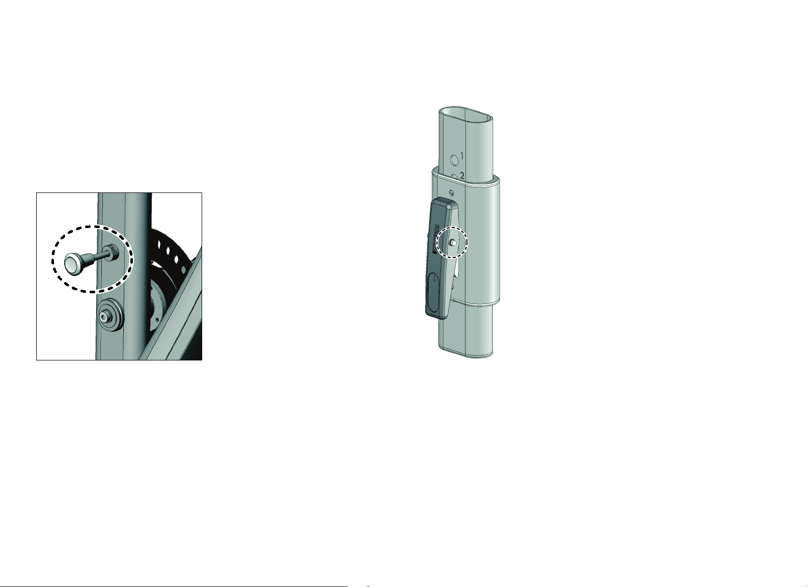
Lubricate Pop Pins
Pull out the pop pin as far as it goes and apply a small amount of Teflon
®
spray
lubricant. Wipe off any excess lubricant with a cloth. (Refer to the following
figure.)
CAUTION: Pulling out the pop pin may cause the unit to adjust position
suddenly. To avoid injury, keep your hands and head away from moving
parts.
Test the pop pin for proper function and engagement in each adjustment hole.
Figure 10: Lubricate the pop pin by pulling it out
Check and Lubricate Ratcheting Seat Lever
The ratcheting seat, which provides audible confirmation of its position as a
user moves it up or down, requires little maintenance. However, because seat
safety is important to the safety of a workout, you should check the seat lever
regularly to see if it sticks when used. You also want to ensure that the pin fully
engages in each adjustment hole.
To test if the seat lever needs lubrication, elevate the seat slightly while
pressing and releasing the lever. The lever should snap back out easily. If the
lever sticks, lubricate its pivot pin with Teflon
®
spray lubricant. Wipe off any
excess lubricant with a cloth. (Refer to the following figure.)
Figure 11: If needed, lubricate the pivot pin on the ratcheting seat lever
If necessary, you can detach the seat by removing the retaining pin, then
remove the chrome for cleaning. Removing the seat also allows clear access to
the ratcheting lever to test its pivoting action.

Vitality Series Selectorized Line Owner's Manual: Maintenance 43
Inspect All Fasteners
Fasteners can loosen with normal use. Inspect all nuts, bolts, screws, and other
fasteners to make sure they are tight and installed correctly.
Be sure to check fasteners at bolted joints to make sure the connections are
secure. If a fastener is loose but in good condition, retighten it. If you are
concerned about the integrity of the fastener, remove it, clean the threads, and
inspect it for any damage such as cracks, bad threads, corrosion, or rust.
Reinstall the fastener if it appears to be in good condition. Otherwise, remove
the equipment from service until a new fastener can be installed properly. You
can order new fasteners from Customer Support. For additional information,
refer to Obtaining Service.
Annual Maintenance
Perform these tasks on an annual basis, as appropriate for your equipment:
Shroud removal.
Weight stack annual maintenance.
Inspect and lubricate pop pins.
Linear ball bearing maintenance.
Weight Stack Annual Maintenance
Once a year, Precor recommends disassembling the weight stack to clean and
inspect it thoroughly.
Carefully remove the cable and guide rods from the weight stack.
Completely disassemble the weight stack in a well-ventilated area, away
from the exercise floor.
Inspect weight plates and clean them thoroughly. Cracked or broken
plates should be replaced immediately (refer to Obtaining Service to
purchase replacements). Clean each plate individually and inspect guide
bushings.
Inspect the bushings of the top weight plate and each individual weight
plate, and replace a plate if it is excessively worn or broken.
Clean the selector stem and inspect it for wear and damage.
Reassemble the weight stack.
Wipe down the weight stack enclosures (shrouds) with a damp cloth as
needed. Inspect all fasteners to make sure the shroud is securely mounted.
Important: Precor recommends that you replace worn and damaged cables during
routine maintenance. It is recommended that all cables be replaced annually.
Vitality Series Selectorized Line Owner's Manual: Maintenance 44
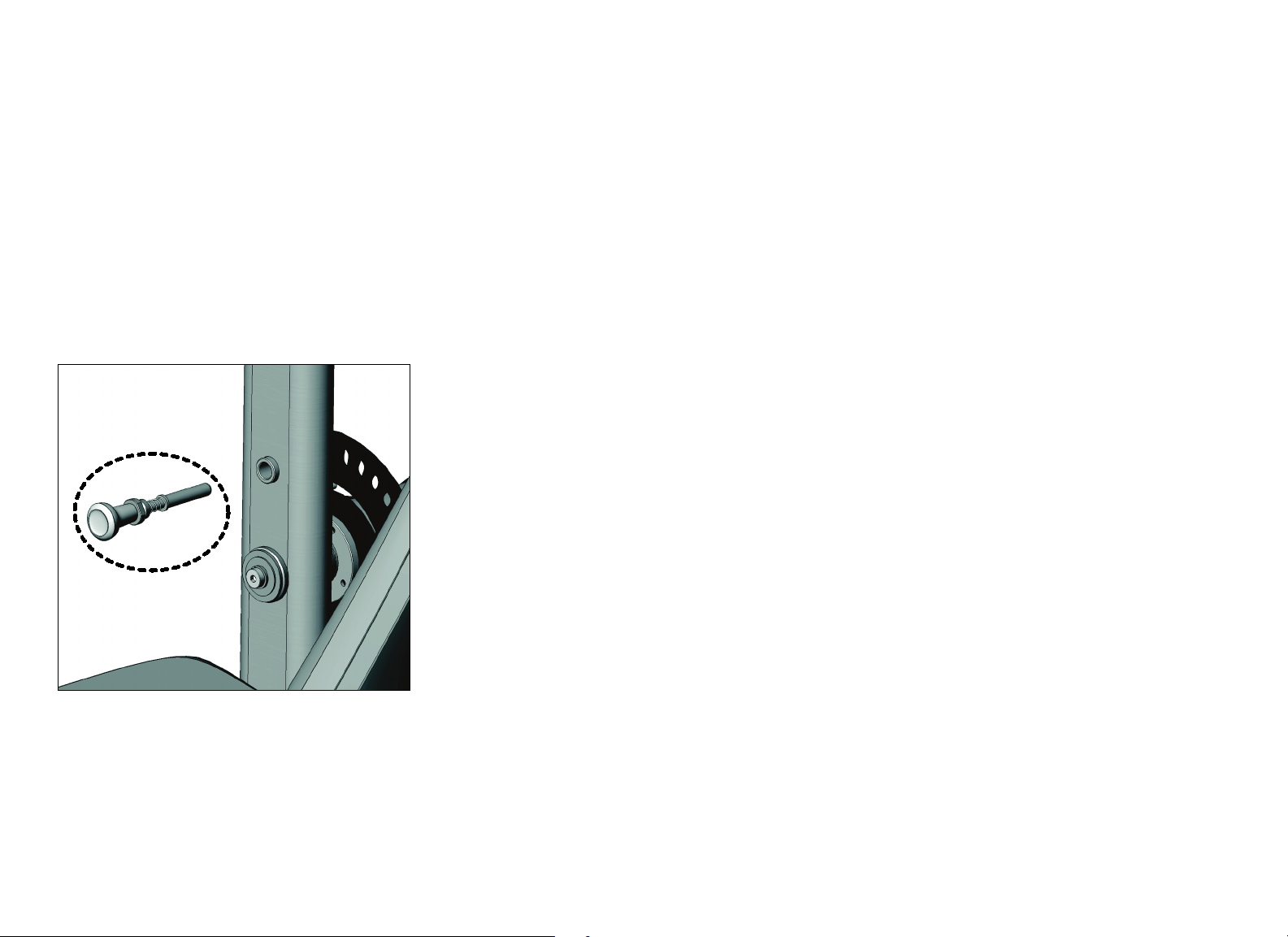
Inspect and Lubricate Pop Pins
Remove the pop pin assembly by loosening the cap.
CAUTION: Pulling out the pop pin may cause the unit to adjust position
suddenly. To avoid injury, keep your hands and head away from moving
parts.
Inspect the plunger and spring for excessive wear and damage, and replace as
required.
Apply a small amount of Teflon
®
spray lubricant to the spring and plunger, and
then reinstall the entire assembly. Tighten the cap. Wipe off any excess
lubricant with a cloth.
Figure 12: Inspect pop pins (pop pin shown in exploded view for clarity)


Precor Incorporated
20031 142nd Ave NE
P.O. Box 7202
Woodinville, WA USA 98072-4002
1-800-347-4404
Precor is a registered trademark of Precor Incorporated.
Copyright 2014 Precor Incorporated.
Specifications subject to change without notice.
www.precor.com
hh
NOTICE:
Precor is widely recognized for its innovative, award winning designs of exercise equipment. Precor
aggressively seeks U.S. and foreign patents for both the mechanical construction and the visual aspects of its
product design. Any party contemplating the use of Precor product designs is hereby forewarned that Precor
considers the unauthorized appropriation of its proprietary rights to be a very serious matter. Precor will
vigorously pursue all unauthorized appropriation of its proprietary rights.
Vitality™ Series Selectorized Line Owner’s Manual
CWR997777-301 rev D, en
31 October 2014
Assembly Guide
Vitality™ Series Selectorized Line
Abdominal / Back Extension


Vitality Series Selectorized Line Abdominal / Back Extension Assembly Guide: Contents 1
Contents
Getting Started ......................................................................................... 2
Open the Boxes ..................................................................................................... 2
Box Contents.......................................................................................................... 2
Assemble the Equipment.......................................................................... 3
Attach the Weight Tower Frame and Foot Pedals to the
Seat Frame.............................................................................................................. 3
Attach the Movement Arm to the Cam Mounting Plate
and Base Support .................................................................................................. 5
Install the Weight Stack Assembly .................................................................. 7
Install the Add-On Weight Assembly............................................................. 8
Tighten All Frame Mounting Hardware.......................................................... 9
Route the Cable Assembly ............................................................................... 10
Adjust the Cable Tension ...................................................................................11
Attach the Seat Pad, Back Pad, and Lumbar Pad.........................................12
Install the Weight Stack Shrouds and the Top Cap ....................................14
Apply the Instructional Label, Outside Precor Equipment Label,
and General Warning Label ..............................................................................15
Verify Operation of the Equipment........................................................ 16
Disassemble the Equipment................................................................... 16
Vitality Series Selectorized Line Abdominal / Back Extension Assembly Guide: Getting Started 2
Getting Started
CAUTION: Do not attempt assembly by yourself. You will need assistance to
assemble this unit.
With assistance, assembly of the Abdominal/Back Extension takes about
40 minutes. In addition, you should allow more time if this is your first time
assembling this equipment.
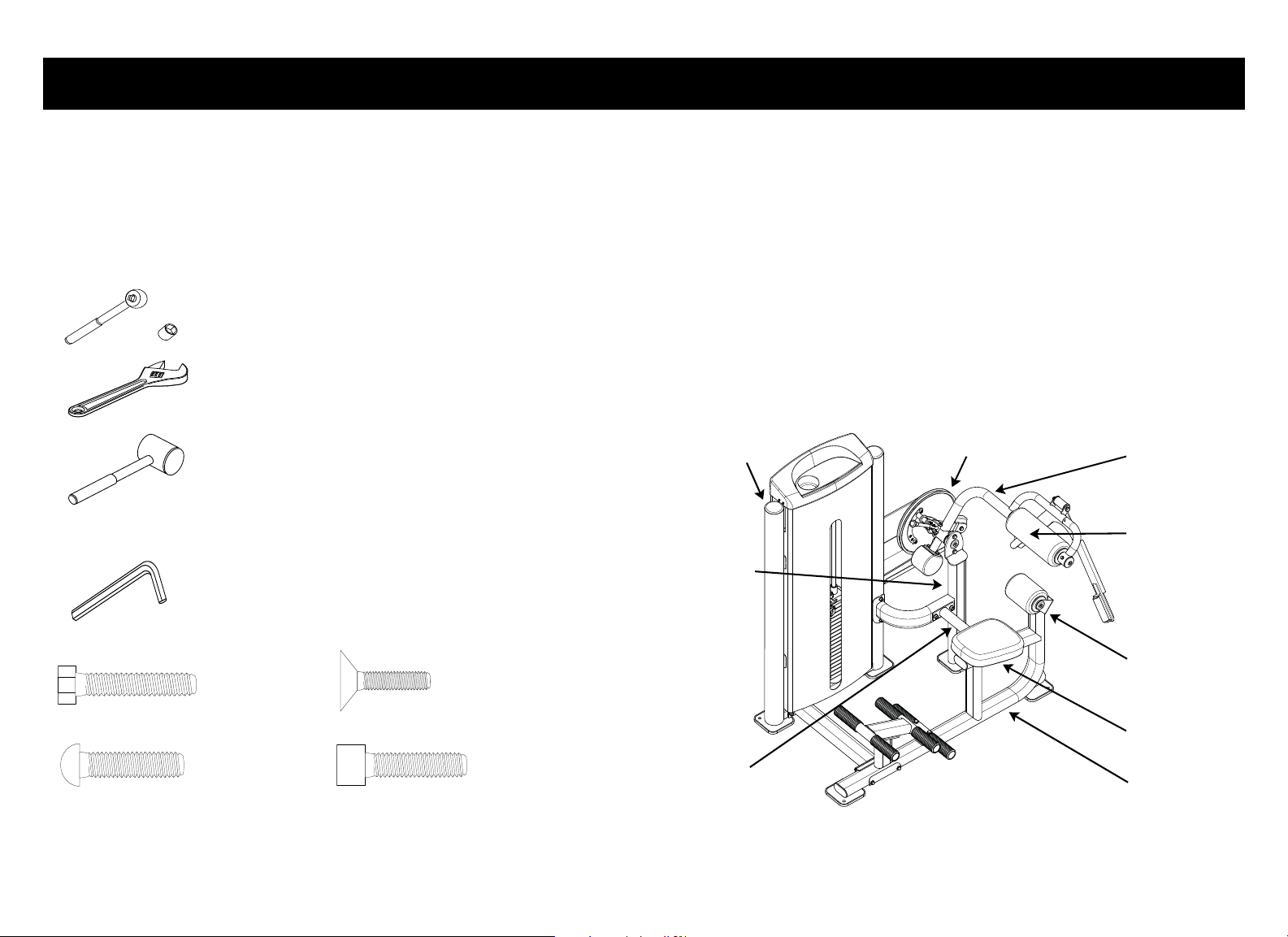
Tools Required
Tools Included
Hardware Guide
Open the Boxes
Open the boxes and remove the packing materials.
Be careful to open boxes and assemble components in the sequence presented
in this manual.
Box Contents:
• Box 1: Weight tower frame, top weight plate, add-on weight assembly,
weight cable, seat frame assembly, movement arm assembly, and hardware
kit
• Box 2: Weight tower shrouds and upholstery pads/rollers
Note: Weight plates are shipped with the equipment but packaged separately.
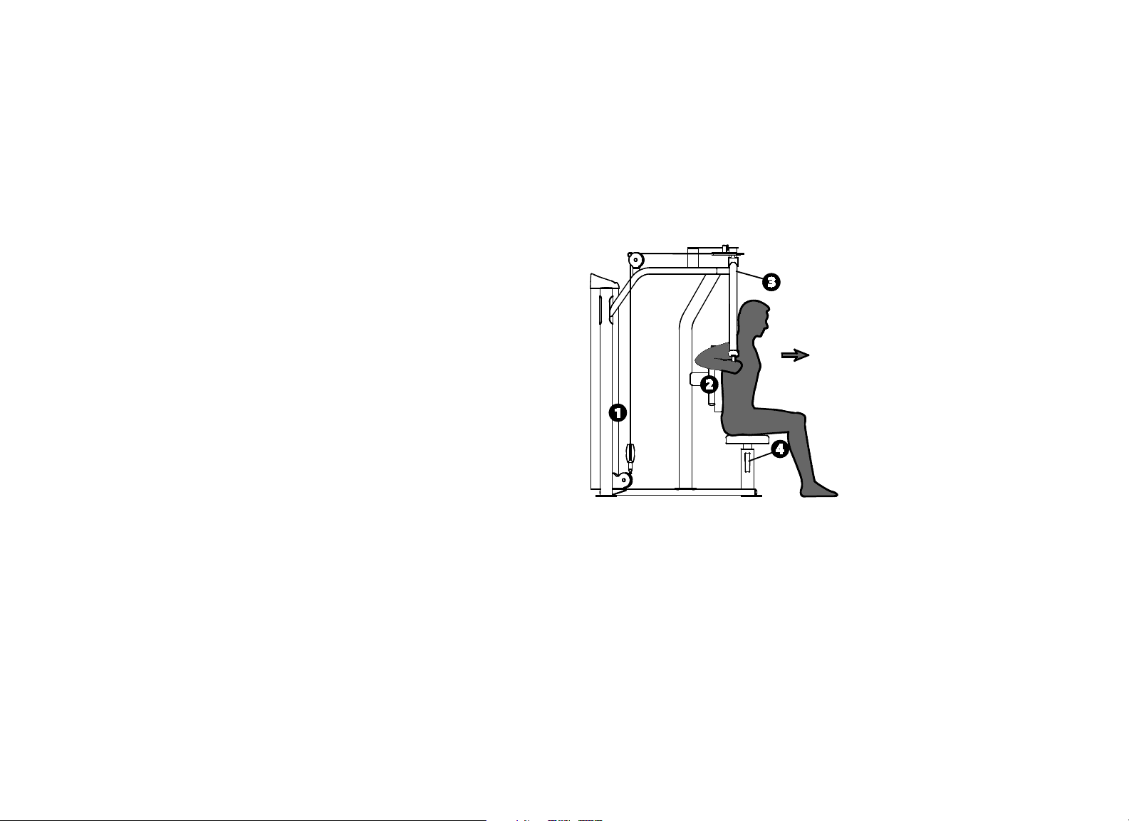
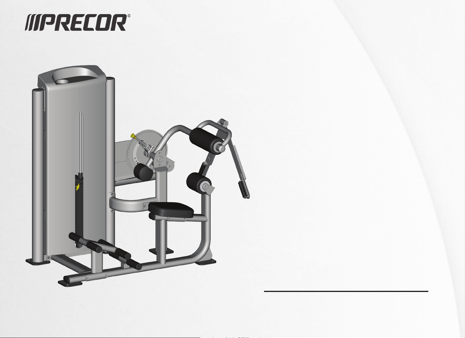
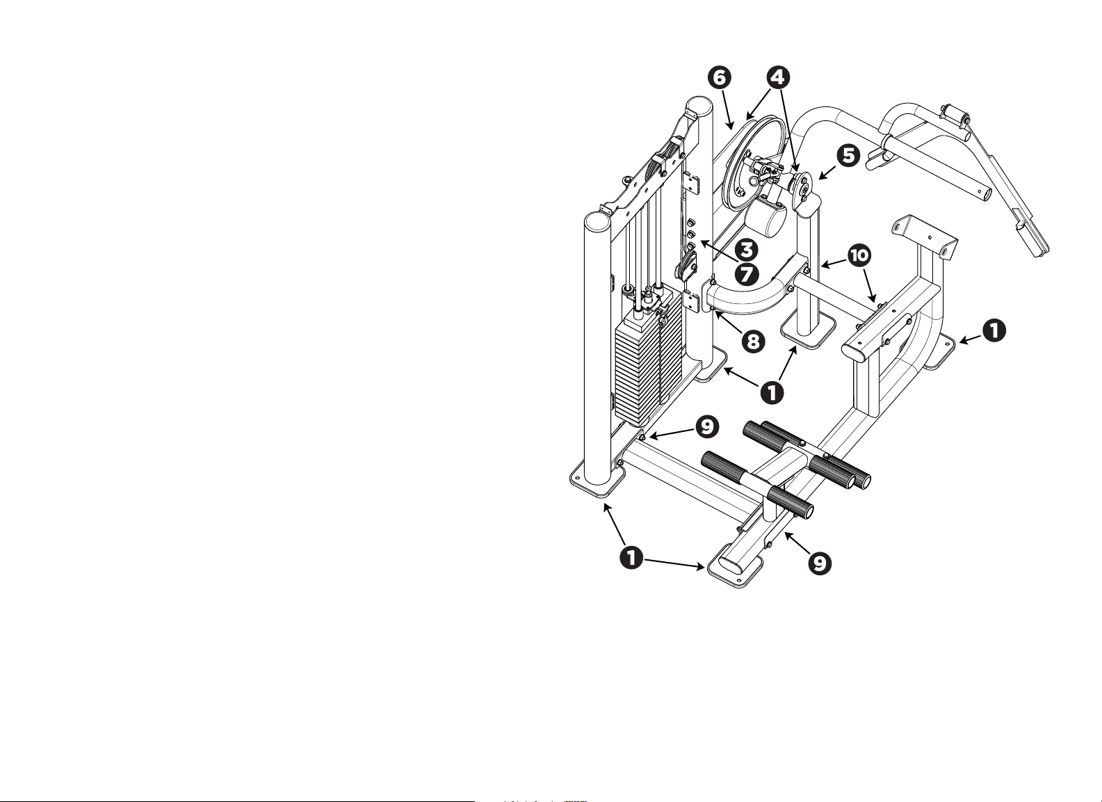
Figure 1: Equipment as assembled. The callouts identify the main components.
Ratchet Wrench and Sockets (metric)
Adjustable Wrench
Rubber Mallet
Hex Key Wrenches
Lumbar Pad
Seat Frame
Weight Tower
Frame
Base/
Pivot Support
Cross Support
Seat Pad
Back Pad
Movement Arm
Cam
HHB = Hex Head Bolt
BHCS = Button Head Cap Screw
FHCS = Flat head Cap Screw
SHCS = Socket Head Cap Screw
Vitality Series Selectorized Line Abdominal / Back Extension Assembly Guide: Assemble the Equipment 3
Assemble the Equipment
CAUTION: Proper alignment and adjustment of the equipment is critical. While
tightening the fasteners, be sure to leave room for adjustments. Do not fully
tighten fasteners until instructed to do so.
Make sure the equipment is stable and placed on a solid surface. The equipment
is designed to be freestanding; however, it can be bolted to the floor for extra
stability. Precor highly recommends that the equipment be bolted to the floor to
reduce the risk of toppling the equipment due to improper use. Since floor
construction varies, please consult a professional building engineer for proper
fastening.
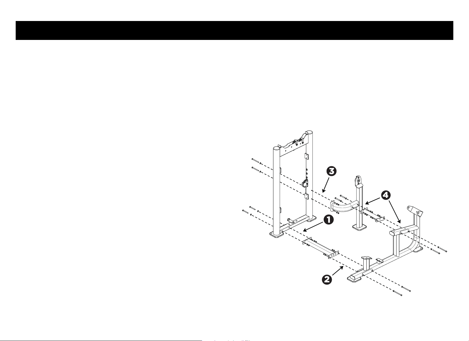
Attach the Weight Tower Frame and Foot Pedals to the Seat Frame
1. Attach the base support to the weight tower frame using:
2 – M10 x 100 mm hex head bolts
4 – 11 mm flat washers
2 – M10 locknuts
Partially tighten the fasteners.
2. Attach the base support to the seat frame using:
2 – M10 x 135 mm hex head bolts
4 – 11 mm flat washers
2 – M10 nylon lock nuts
Note: Partially tighten the fasteners.
3. Attach the pivot support to the weight tower frame using:
2 – M10 x 125 mm hex head bolts
4 – 11 mm flat washers
2 – M10 nylon lock nuts
Tighten these fasteners completely.
Note: Position the pivot support tube as shown in the illustration, with the
pillow-block bearing facing the cam mounting plate.
4. Attach the pivot support tube to the seat frame with the cross support
using:
2 – M12 x 80 mm hex head bolts (cross support to pivot support)
2 – M10 x 130 mm hex head bolts (cross support to seat frame)
4 – 13 mm flat washers
4 – 11 mm flat washers
2 – M12 nylon lock nuts
2 – M10 nylon lock nuts
Figure 2: Major frame component assembly
Vitality Series Selectorized Line Abdominal / Back Extension Assembly Guide: Assemble the Equipment 4
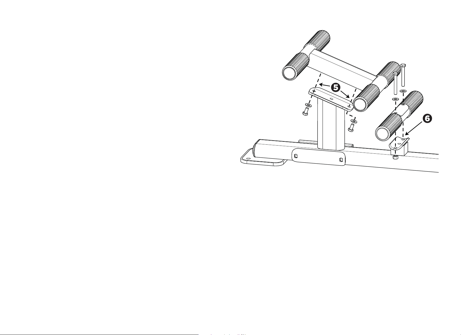
5. Attach the double foot pedals to the seat frame using:
2 – M10 x 20 mm hex head bolts
2 – 11 mm flat washers
Note: The foot pedal assembly can be tightened completely.
6. Attach the single foot pedals to the seat frame using:
2 - M10 x 75 mm hex head bolts
2 - 11 mm flat washers
Note: The bolts fit into threaded nuts on the seat frame, from the top down.
This foot pedal assembly can also be tightened completely.
Figure 3: Foot pedal assembly
Vitality Series Selectorized Line Abdominal / Back Extension Assembly Guide: Assemble the Equipment 5
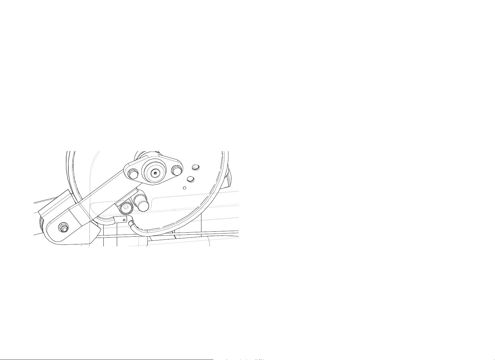
Attach the Movement Arm to the Cam Mounting Plate and Base
Support
Note: To simplify this procedure, you may want to back out the set screws on the
two pillow-block bearings before you begin.
1. Attach the movement arm to the pivot support. Slide the round end of the
axle into the pillow-block bearing on the pivot support until it stops. Tighten
the two set screws to hold the axle in place.
2. Have your assistant support the movement arm while you guide the
movement arm onto the axle. Have your assistant continue to support the
movement arm.
Note: There are two metal flanges on the pulley arm assembly. Position
these stops so that they rest on top of the stops on the cam support plate
and on the cam itself.
Figure 4: Pulley positioning on cam and cam support plate stops
3. Slide the cam and pulley arm assembly onto the axle, making sure that the
rubber stops on the cam are facing the cam support plate (and facing away
from the user).
4. Slide the pillow-block bearing over the end of the axle until it stops.
5. Insert the cam support plate into the slot in the weight tower frame and
attach it securely using:
3 – M12 x 65 mm hex head bolts
3 – 13 mm flat washers
Note: The cam support plate can be tightened completely.
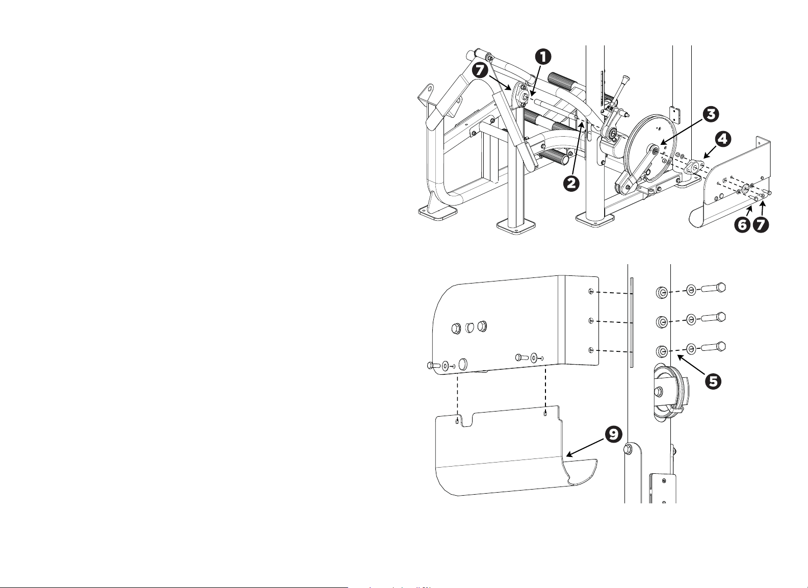
Vitality Series Selectorized Line Abdominal / Back Extension Assembly Guide: Assemble the Equipment 6
6. Secure the movement arm and the pillow-block bearing to the cam support
plate using:
2 - M12 x 40 mm hex head bolts (secured on the side opposite the
pillow-block bearing)
2 - Barrel spacers (fit into mounting holes on pillow-block bearing)
4 - 13 mm flat washers
2 - M12 nylon lock nuts (secured on the pillow-block bearing side)
Note: If necessary, rotate the axle until its keyed end fits into the hole in the
cam support plate.
7. Secure the movement arm and the cam support plate to the pivot support
tube using:
2 – M10 x 25 mm flat head cap screws
2 – Aluminum caps
8. Using a long hex wrench, tighten the two set screws on the pillow-block
bearing attached to the cam support plate.
9. Align the cam cover as follows:
— It is positioned along the inside of the cam support plate.
— Its two mounting holes line up with the two mounting holes near the top
edge of the cam support plate.
— Once installed, its recessed end fits snugly against the weight tower
upright.
— Once installed, its curved portion extends over the movement arm
cable.
Attach the cam cover to the cam support plate using:
2 – M8 x 25mm hex head bolts
2 – 9 mm flat washers
Figure 5: Movement arm attachment
Figure 6: Cam support plate attachment
Vitality Series Selectorized Line Abdominal / Back Extension Assembly Guide: Assemble the Equipment 7
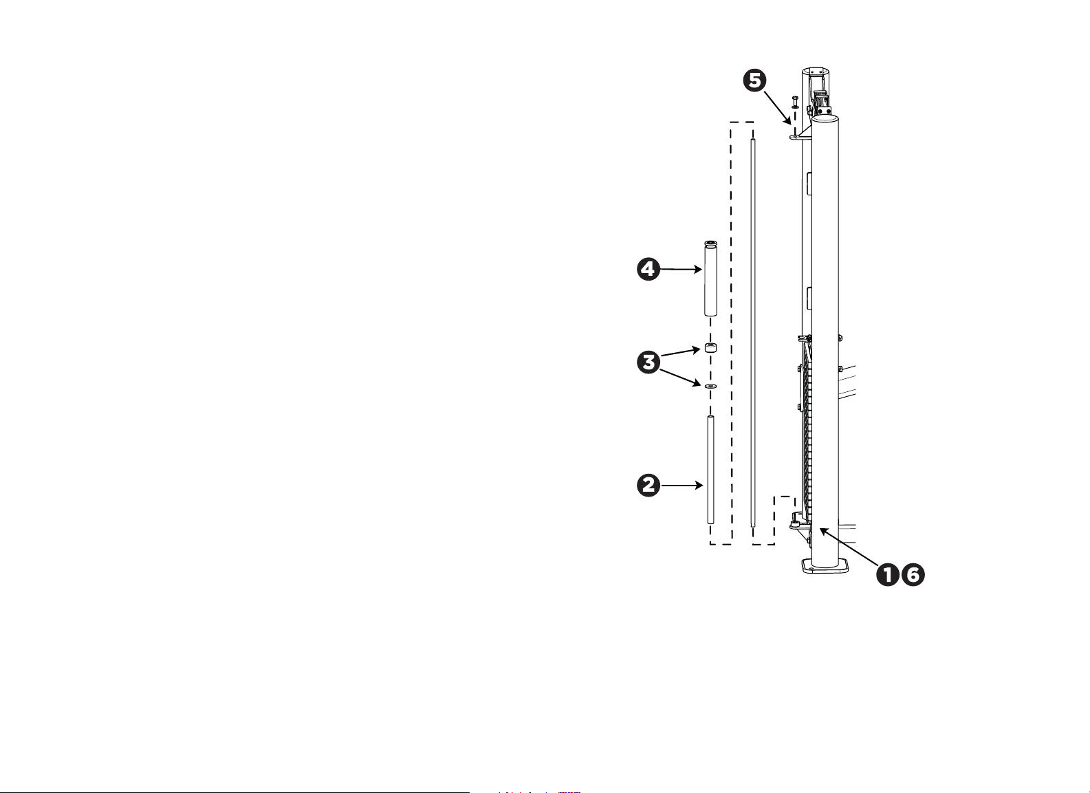
Install the Weight Stack Assembly
1. Insert the guide rods into the holes at the bottom of the weight tower frame.
Important: A hole passes through one end of each guide rod. Be sure to insert the
end with the hole into the bottom of the frame.
2. Pull the guide rods away from the frame, keeping their lower ends engaged
in the bottom of the frame. Slide one weight stack bumper over each guide
rod, narrow end up.
3. Check the guide rods for silicone lubricant. If you do not find any, add some
of the lubricant supplied in the hardware kit to the guide rods.
4. Carefully slide nineteen 10 lb. (4.5 kg) weight plates onto the guide rods,
one by one.
5. If the cable assembly is attached to the top weight plate, then unscrew it
and remove it at this time. Slide the ring at the end of the tether on the
weight selection pin over the right-hand post on the top weight plate.
6. Slide the top weight plate with weight stack stem onto the two guide rods
and then lower the stem through the center holes of the weight plates. Make
sure the yellow T-handle on the top weight plate faces the user’s position.
7. Secure the weight stack assembly to the weight tower frame. Slide the guide
rod locking collars onto the guide rods (the smaller diameter shoulder on
the collar should be facing up). Re-align the guide rods with the mounting
holes at the top of the weight tower.
8. Have your assistant hold the guide rods in place. Slide the collars up until the
shoulder of each collar fits into the tower frame. Secure the collars to the
guide rods by tightening the M8 set screws using the S4 hex key.
9. Apply the weight plate labels (select LBs or KGs) to the left of the weight
selection holes.
Figure 7: Weight stack installation
Vitality Series Selectorized Line Abdominal / Back Extension Assembly Guide: Assemble the Equipment 8
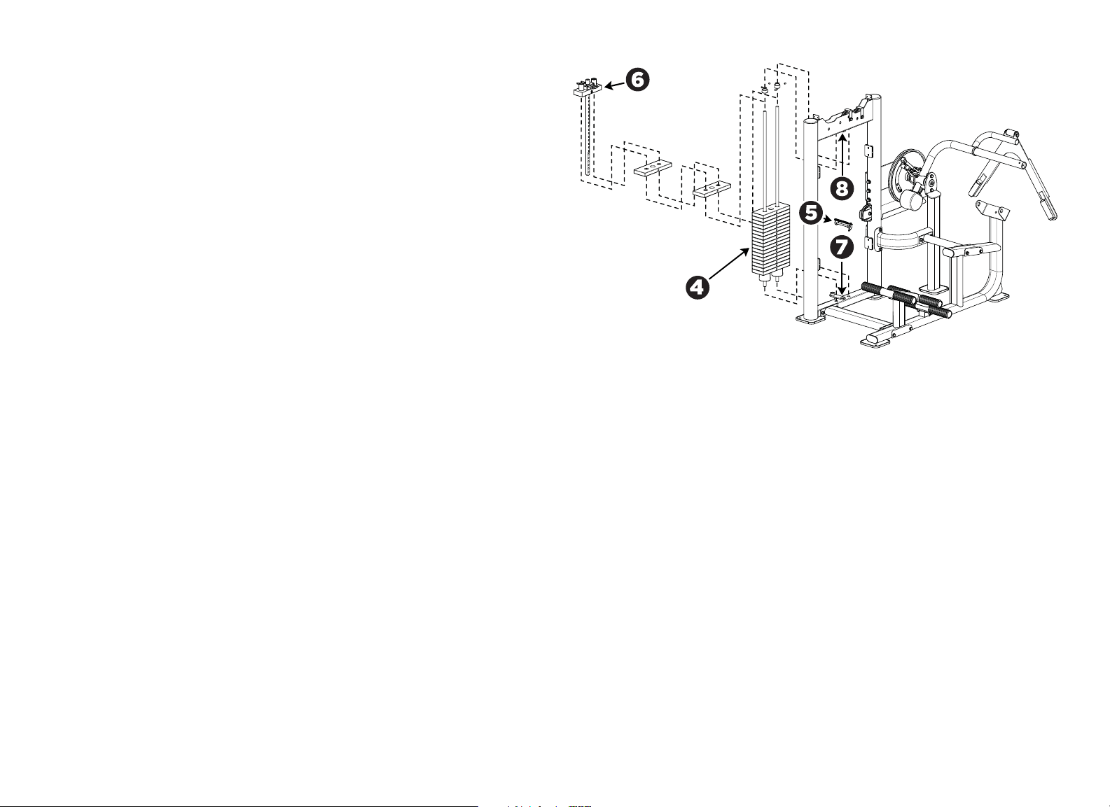
Install the Add-On Weight Assembly
1. Insert the lower end of the 14 mm guide rod into the retaining ring at the
bottom of the weight tower frame.
Note: The end of the guide rod with the screw hole in it should face up. Also,
you may need to loosen the set screws in the retaining ring to seat the guide
rod completely.
2. Slide the 287 mm support tube onto the guide rod from the top down.
3. Slide the support ring onto the guide rod, followed by the rubber bumper.
4. Slide the 5 lb (2.5 kg) add-on weight onto the guide rod, making sure that
the groove is at the top end of the weight.
5. Attach the top of the guide rod to the bracket at the top of the weight tower
frame using:
1 – M10 x 25 mm hex head bolt
1 – 11 mm flat washer
6. Fully tighten the M8 set screw in the retaining ring using the S4 hex key.
Figure 8: Add-on weight installation
Vitality Series Selectorized Line Abdominal / Back Extension Assembly Guide: Assemble the Equipment 9
Tighten All Frame Mounting Hardware
1. Check that the weight tower and seat frame are sitting evenly on the floor.
2. Verify that the movement arm is parallel to the floor when it is at rest.
3. Loosen the three bolts attaching the cam support plate to the weight tower.
4. Loosen the bolts attaching the two pillow-block bearings.
5. While your assistant holds the movement arm parallel to the floor, tighten
the bolts securing the pillow-block bearing on the pivot support.
Note: Your assistant should continue to hold the movement arm parallel to
the floor until you complete step 8.
6. Tighten the bolts securing the pillow-block bearing on the cam support
plate.
7. Tighten the bolts securing the cam support plate to the weight tower.
8. Recheck that the mounting hardware securing the cross support to the
weight tower is still tight. If not, tighten it.
Note: Your assistant should be able to the release the movement arm. The
movement arm should remain parallel to the floor.
9. Tighten the mounting hardware at the base support.
10. On the seat frame, tighten the mounting hardware at the base support, then
at the cross support.
Figure 9: Frame mounting hardware locations
If the movement arm is.... Then
Parallel to the floor Skip to step 9.
Not parallel to the floor Continue with step 3.
Vitality Series Selectorized Line Abdominal / Back Extension Assembly Guide: Assemble the Equipment 10
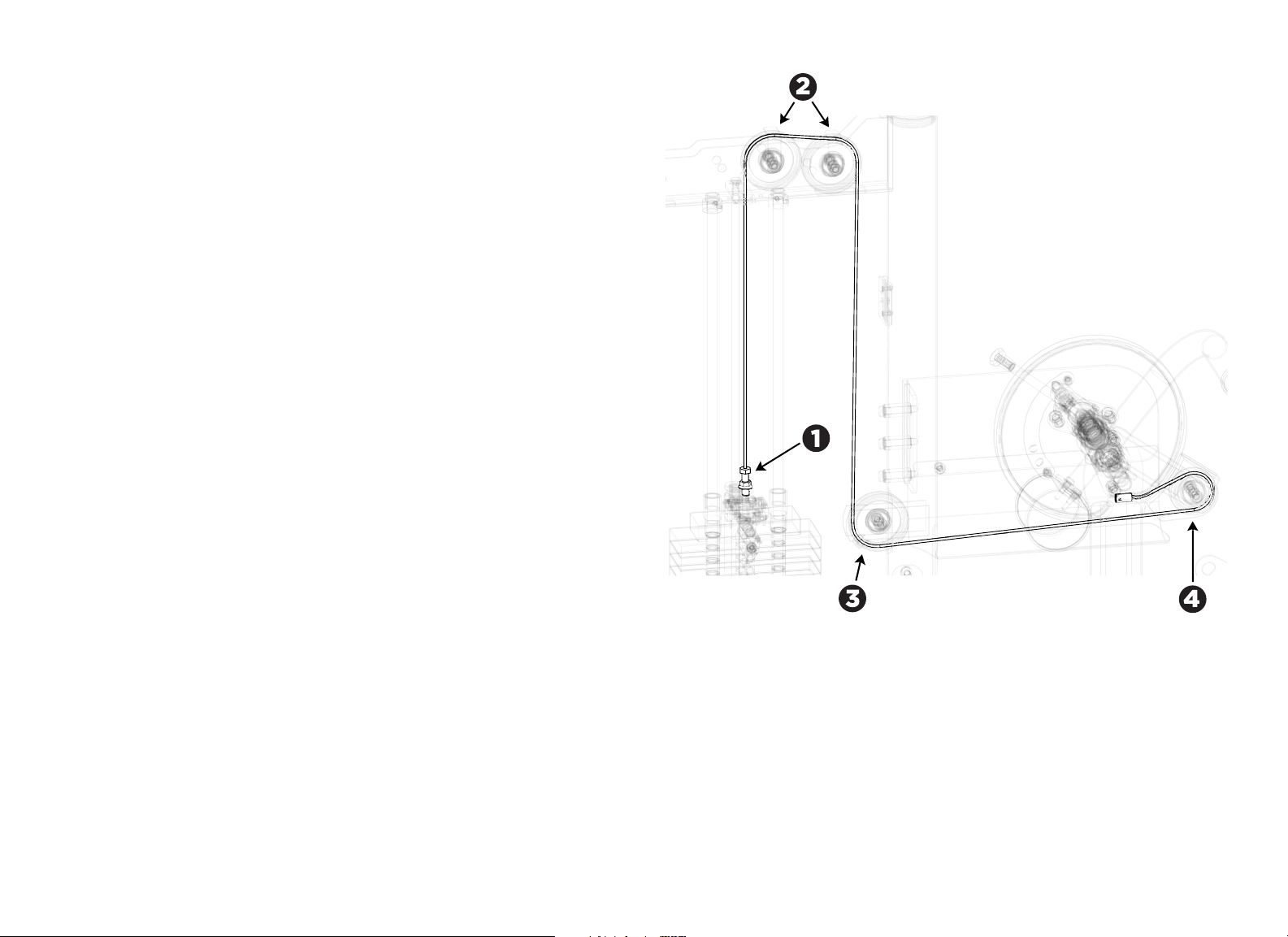
Route the Cable Assembly
1. Screw one end of the cable assembly into the top of the weight stack stem.
CAUTION: Be sure that at least seven (7) threads are inserted into the fitting.
2. Pull the cable through the top of the weight tower frame, over the top of the
dual pulleys, and under the cable retaining brackets.
Note: The pulleys do not need to be removed.
3. Pass the cable to the pulley at the middle of the tower upright. Thread the
cable between the cable retainers, under the pulley, and through the tower
upright.
Note: To make the following step easier, brace the top weight plate in a
raised position. Remove the brace and return the top weight plate to its
normal position after the end of the cable is in place.
4. Thread the cable under and around the pulley on the cam assembly, then
insert its end into the cable slot on the cam. Secure the cable with an
M4-15 mm screw.
Note: The screw is pre-assembled to the cam. First, remove the screw, then
install the cable into the slot on the cam and replace the screw.
Figure 10: Cable assembly detail
Vitality Series Selectorized Line Abdominal / Back Extension Assembly Guide: Assemble the Equipment 11
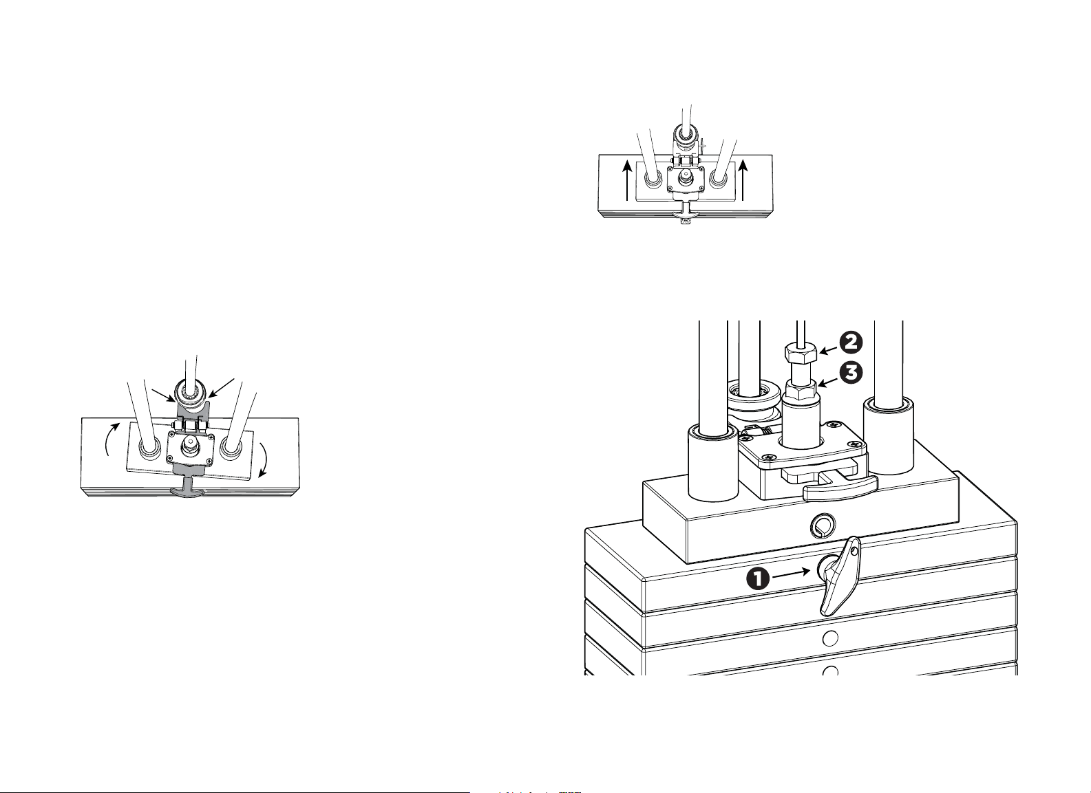
Adjust the Cable Tension
1. Place the weight selection pin in the top weight.
2. Screw the cable bolt into the selector stem until the cable meets the
following requirements:
— No excess slack remains.
— The cable is just loose enough to permit insertion of the selector pin into
any of the weight plates.
— At least seven (7) threads on the cable bolt extend into the selector
stem.
3. Hold the weight twoer straight while tightening the locking jam nut against
the selector stem. If you do not hold the weight tower straight, it can twist
(see Figure 8).
Important: Screw the cable bolt into the selector stem until at least seven (7)
threads on the cable bolt extend into the selector stem.
Figure 11: Misaligned weight tower
4. Once tightened, verify alignment between the selector and the add-on
weight.
Figure 12: Properly aligned weight tower
5. Check the adjustment by inserting the weight pin into every weight plate
hole. The weight pin should slide easily in and out of each weight plate.
Figure 13: Cable management detail
Vitality Series Selectorized Line Abdominal / Back Extension Assembly Guide: Assemble the Equipment 12
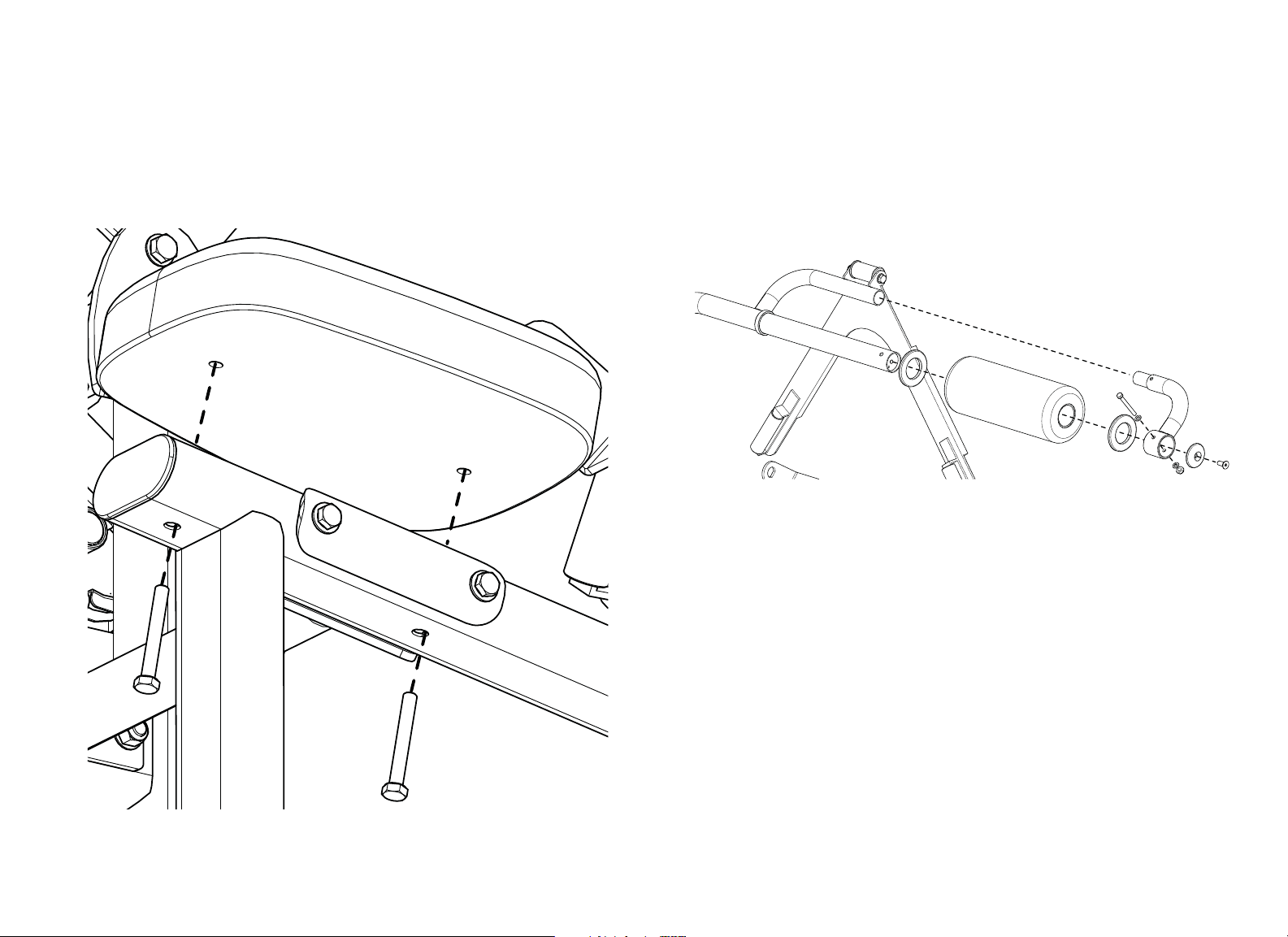
Attach the Seat Pad, Back Pad, and Lumbar Pad
1. Attach the seat pad to the seat frame using:
2 – M10 x 75 mm hex head bolts
2 – 11 mm flat washers
Note: The round end of the pad should face forward.
Figure 14: Seat pad attachment
2. Attach the back roller pad to the movement arm. Remove the end section of
the back roller pad and shoulder strap tube by detaching:
1 – M8 x 70 mm hex head bolt
2 – 9 mm flat washer
1 – M8 nut
Slide the back roller pad over the end of the movement arm, then replace the
fasteners you just removed.
Figure 15: Back pad attachment
Vitality Series Selectorized Line Abdominal / Back Extension Assembly Guide: Assemble the Equipment 13
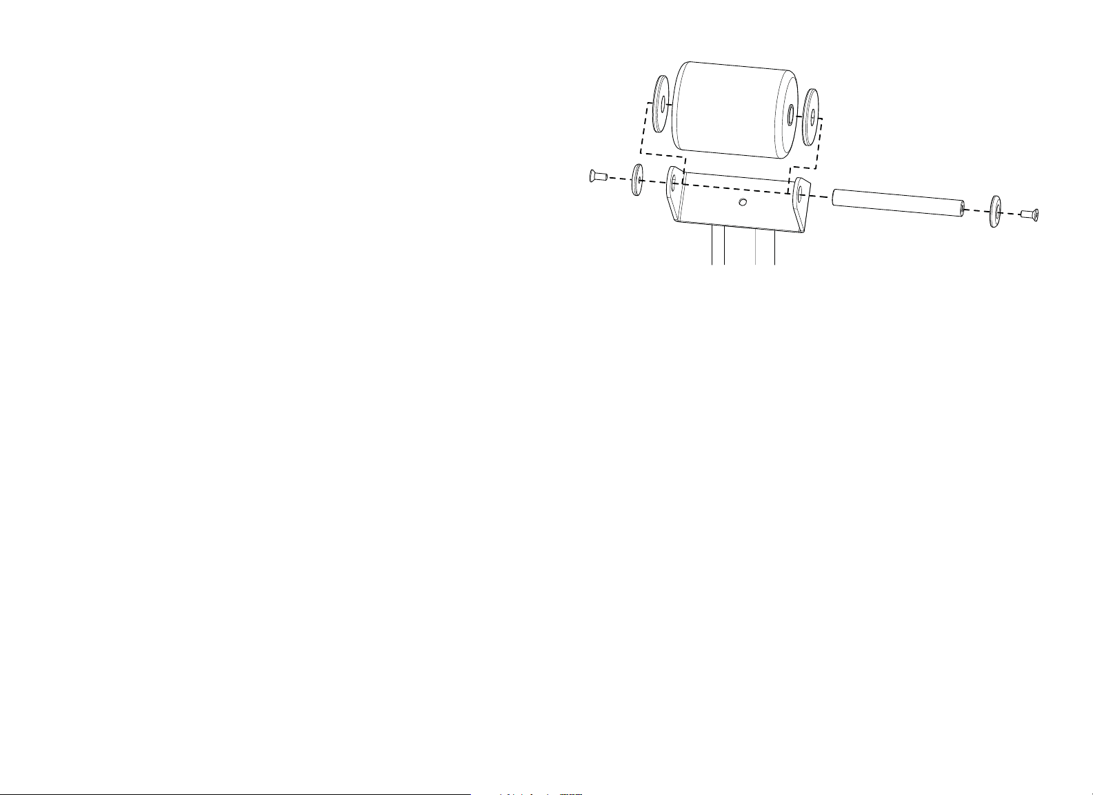
3. Attach the lumbar roll pad to the seat frame using:
2 – Large aluminum trim washers
2 – Aluminum end caps
2 – M10 x 25 mm flat head cap screws
1 – Shaft (208 mm)
Note: The large aluminum trim washers sit in between the roller pad and the
mounting bracket. The aluminum end caps attach on the outside of the
mounting bracket.
Figure 16: Lumbar pad attachment
Vitality Series Selectorized Line Abdominal / Back Extension Assembly Guide: Assemble the Equipment 14
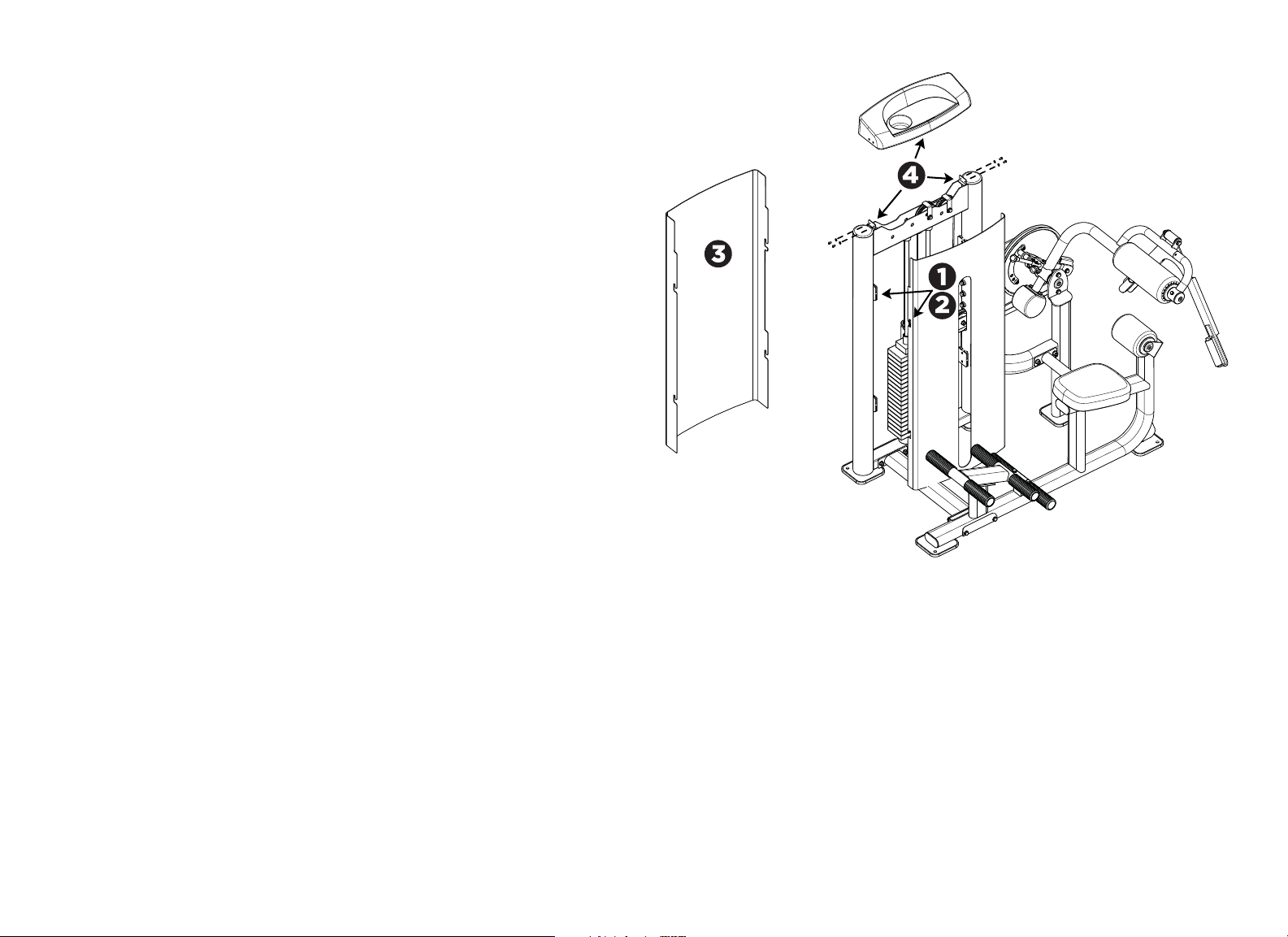
Install the Weight Stack Shrouds and the Top Cap
Note: The inside shroud has a slot for weight selection. Both shrouds have two
slotted tabs on each side that fit into the shroud clips mounted to the inside of
the weight tower uprights.
1. Align the slotted tabs on the inside shroud with the shroud clips on both
sides of the weight tower.
2. Press the hooks into the clips and lower the shroud securely into place.
3. Repeat steps 1 and 2 to install the outside shroud.
4. Place the top cap on top
of the shrouds so that the top edges of the shrouds fit
into the slot between the lip and the ribs of the top cap. Secure
the top cap to
the weight tower frame using
:
4 – M6 x 12 mm button head bolts
4 – 7 mm flat washers
Note: When you secure the top cap, if the top edges of the shrouds do not fit
securely into the slot between its lip and ribs, remove the cap and the shrouds.
Loosen the fasteners securing each of the shroud clips, then secure each clip
again so that it is mounted as high on the weight stack frame as possible. You will
need to push the clips up and hold them in place while you secure them. After
you have repositioned all of the shroud clips, repeat this procedure to install the
shrouds and the top cap.
Figure 17: Weight stack shroud and top cap assembly
Vitality Series Selectorized Line Abdominal / Back Extension Assembly Guide: Assemble the Equipment 15
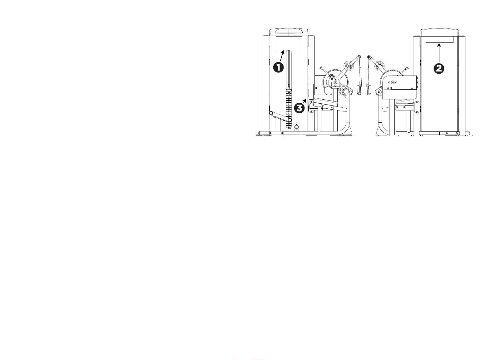
Apply the Instructional Label, Outside Precor Equipment Label, and
General Warning Label
1. Attach the Instructional label to the inside shroud under the top cap. The
label should be aligned with the left and right edge of the tray on the top cap.
There are small marks on the lower lip of the top cap to indicate the proper
label position.
2. Attach the Precor Equipment label to the outside shroud by centering it
under the top cap. There are small marks on the lower lip of the top cap to
indicate the proper label position.
3. Attach the General Warning label to the right tower frame upright. The
bottom of the label should be aligned 35 mm (1.38 inches) above the cross
support mounting.
Figure 18: Instructional label, General Warning label, and Precor Equipment label
placement

Vitality Series Selectorized Line Abdominal / Back Extension Assembly Guide: Verify Operation of the Equipment 16
Verify Operation of the Equipment
Once assembly is complete, verify safe operation by checking the following
points:
• Cable tension is correct and the cable is moving smoothly on its pulleys.
• Movement arm is stable and moves smoothly through its range of motion.
• Adjustment points are stable and move smoothly through their range of
motion.
Disassemble the Equipment
You may occasionally need to disassemble this unit to move it between rooms or
buildings. In such cases, reverse the assembly steps in this manual to perform
the disassembly. After the unit has been moved, follow the steps in this manual
to reassemble it.
WARNING: You will need assistance to disassemble this unit. The weight tower
can become unstable during parts of the disassembly process. Make sure the
weight tower is supported safely throughout disassembly, and NEVER attempt
disassembly by yourself.


Precor Incorporated
20031 142nd Ave NE
P.O. Box 7202
Woodinville, WA USA 98072-4002
1-800-347-4404
Precor is a registered trademark of Precor Incorporated.
Copyright 2012 Precor Incorporated.
Specifications subject to change without notice.
www.precor.com
NOTICE:
Precor is widely recognized for its innovative, award winning designs of exercise equipment. Precor
aggressively seeks U.S. and foreign patents for both the mechanical construction and the visual aspects of its
product design. Any party contemplating the use of Precor product designs is hereby forewarned that Precor
considers the unauthorized appropriation of its proprietary rights to be a very serious matter. Precor will
vigorously pursue all unauthorized appropriation of its proprietary rights.
Vitality™ Series Selectorized Line
Abdominal / Back Extension Assembly Guide
CWR287777-141 rev B, en
11 October 2012