
Assembly and Maintenance Guide
S3.15
Strength-Training
Fitness Equipment

S3.15 Assembly and Maintenance Guide
page 2
IMPORTANT SAFETY INSTRUCTIONS
Important Safety Instructions
Important Safety Instructions
Before beginning any fitness program, see your
physician for a complete physical examination.
Il est conseillé de subir un examen médical complet
avant d’entreprendre tout programme d’exercise. Si
vous avez des étourdissements ou des faiblesses,
arrêtez les exercices immédiatement.
When using exercise equipment, basic precautions
should always be taken, including the following:
• Read all instructions before using the S3.15
equipment. These instructions are written for your
safety and to protect the unit.
• Do not allow children or those unfamiliar with its
operation on or near the equipment. Do not leave
children unsupervised around the unit.
• Use the equipment only for its intended purpose as
described in this manual. Do not use accessory
attachments that are not recommended by the
manufacturer, as such attachments may cause
injuries.
• Wear proper exercise clothing and shoes for your
workout and avoid loose clothing. Tie long hair
back.
• Use care when getting on or off the unit.
• Do not overexert yourself or work to exhaustion.
• If you feel any pain or abnormal symptoms,
stop your workout immediately and consult
your physician.
• Never operate the unit when it has been dropped
or damaged. Return the equipment to a service
center for examination and repair.
• Never drop or insert objects into any opening.
Keep hands away from moving parts.
• Always check the unit and its cables before each
use. Make sure that all fasteners and cables are
secure and in good working condition.
• Do not use outdoors.
Personal Safety During Assembly
• It is strongly recommended that a qualified
dealer assemble the equipment.
Assistance is
required.
• Read each step in the assembly instructions and
follow the steps in sequence. Do not skip ahead. If
you skip ahead, you may learn later that you have
to disassemble components and that you may
have damaged the equipment.
• Assemble and operate the S3.15 on a solid, level
surface. Locate the unit a few feet from walls or
furniture to provide easy access.
Obtaining Service
Do not attempt to service the S3.15 yourself
except for the maintenance tasks described
in this guide. This unit does not contain any
user-serviceable parts.
For information about product operation,
or service, refer to the Precor web site at
www.precor.com. Should you need more
information regarding customer support
numbers or a list of Precor authorized
service centers, visit the Precor web site
at www.precor.com/cons.
If you call or e-mail Customer Support,
have the serial number and part numbers
available.
You can find the serial number printed on
a label affixed to the side of the S3.15. For
future reference, write the serial number in
the space provided below.
Serial number: _______________________

S3.15 Assembly and Maintenance Guide
page 3
Table of Contents
1
2
3
Important Safety Instructions .................................................................................. 2
Personal Safety During Assembly ............................................................................................................ 2
Obtaining Service ..................................................................................................................................... 2
Before You Begin ....................................................................................................... 4
Unpacking the Equipment......................................................................................................................... 4
Optional Equipment .................................................................................................................................. 4
Preparations .............................................................................................................. 5
Required Tools .......................................................................................................................................... 5
Installation Requirements ......................................................................................................................... 5
Assembly Tips........................................................................................................................................... 5
Assembly Instructions .............................................................................................. 6
Open the Box ............................................................................................................................................ 7
1. Assemble Main Structure.............................................................................................................. 8
2. Assemble Leg Extension .............................................................................................................. 10
3. Install Seat and Rollers ................................................................................................................. 11
4. Assemble Weight Stack ................................................................................................................ 13
5. Assemble Press Arm .................................................................................................................... 15
6. Install Main Cable ......................................................................................................................... 17
7. Install Ab Cable and Floating Pulleys ........................................................................................... 19
8. Install Leg Extension Cable .......................................................................................................... 20
9. Install Leg Press Option Cable Connection .................................................................................. 22
10. Attach Upper Shrouds .................................................................................................................. 23
11. Attach Accessories ....................................................................................................................... 24
12. Apply Weight Decals and Lubricant .............................................................................................. 25
Cable Adjustments and Maintenance ...................................................................... 26
1. Cable Tension ............................................................................................................................... 27
2. Cable Adjustments........................................................................................................................ 28
3. Maintenance ................................................................................................................................. 29
Appendix – Shrouds ................................................................................................................................. 31
Limited Warranty Statement ..................................................................................................................... 32
Warranty Registration Card ...................................................................................................................... 33
Specifications .............................................................................................................................. Back cover
Table of Contents
4
S3.15 Assembly and Maintenance Guide
page 4
1
Before You Begin
Before You Begin
Thank you for purchasing the S3.15. This unit is part of
the Precor Strength line of quality strength training
machines, which let you target specific muscle groups
to achieve better muscle tone and overall body
conditioning. To maximize your use of the equipment,
please study this guide thoroughly.
Unpacking the Equipment
The S3.15 is carefully tested and inspected before
shipment. Precor Strength ships the unit in several
pieces that require assembly. Ask for assistance during
the assembly process.
• Review the
Installation Requirements
.
• When instructed to open a box, carefully unpack
the pieces and lay them on the floor near the
location where you plan to use the equipment.
Be careful to open boxes and assemble components in
the sequence presented in this manual.
If any items are missing, contact the dealer from whom
you purchased the unit. For more information, refer to
Obtaining Service
.
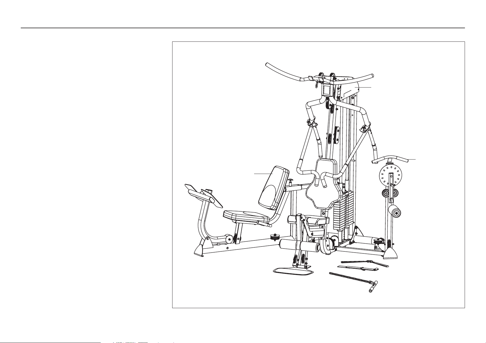
Optional Equipment
• S3.15 Leg Press Option
• S3.15 Multi-Hip Option
• Heavy Stack Option (Additional 50 lb weight stack)
• Shrouds
S3.15
Leg Press Option
Multi-Hip Option

S3.15 Assembly and Maintenance Guide
page 5
2
Preparations
Preparations
CAUTION: To set up this unit, you will need
assistance. Do not attempt assembly by yourself.
You must review and follow the instructions in this
guide. If you do not assemble and use the S3.15
according to the following guidelines, you could void
the Precor Limited Warranty.
Required Tools
Tools that you need to obtain before assembling the
unit include:
❏ ⁹⁄₁₆-inch socket
❏ ³⁄₄-inch socket
❏ ⁹⁄₁₆-inch box-end wrench
❏ ³⁄₄-inch box-end wrench
❏ Crescent wrench
❏ Rubber mallet
❏ Wire tie cutter (cuts plastic tie wraps)
❏ Utility knife
❏ Step stool
Installation Requirements
Follow these installation requirements when
assembling the unit:
• Fill out and mail the warranty registration card.
• Set up the S3.15 on a solid, flat surface.
A smooth, flat surface under the unit helps keep
it level.
• Provide ample space around the machine.
Open space around the machine allows for easier
access.
• Insert all fasteners in the same direction. For
aesthetic purposes, insert all the fasteners in the
same direction unless specified (in text or
illustrations) to do otherwise.
• Leave room for adjustments. Tighten fasteners
(such as screws, nuts, and bolts), so the unit is
stable, but leaves room for adjustments. Do not
fully tighten fasteners until instructed (in the steps)
to do so.
Assembly Tips
• Fasteners may become loose and fall off during
shipment. Inspect the plastic wrap and packaging
for loose parts. To alleviate confusion during
assembly, reattach the loose fasteners and pulleys
found in the packaging.
• A black 6-inch scale with white numbers is
provided at the bottom of every assembly
instruction page. Use this scale to identify the
correct fastener size. The head of a fastener is not
used in measuring the length.
• Most fasteners are ³⁄₈-inch unless otherwise noted.
To find out the length of a particular fastener,
measure its shank (the long, narrow part beneath
the head). Refer to the following diagram:
• Silver-colored zinc fasteners are used with the
titanium parts (Press Arm, Floating Pulleys, etc.).
Black fasteners are used when assembling the
stone gray painted surfaces.
• Some pieces have extra holes that you will not use.
Use only those holes indicated in the instructions
and illustrations.
• Read all caution notes on each page before
completing that step.
• While you may be able to assemble the S3.15 by
reading the illustrations only, refer to the text for
important safety cautions and notes.
Fastener head
Fastener threads
Shank
To determine the
length of a fastener,
measure its shank.
S3.15 Assembly and Maintenance Guide
page 6
1 2 3 4 5 6
3
Assembly
Instructions
Assembly Instructions
Assembly of the S3.15 takes professional installers
about 1½ hours to complete. If this is the first time you
have assembled this type of equipment, plan on
significantly more time.
Professional installers are highly recommended!
However, if you acquire the appropriate tools, obtain
assistance, and follow the assembly steps sequentially,
the process will take time, but is fairly easy.
CAUTION: Obtain assistance! Do not attempt to
assemble the S3.15 by yourself. Review the
Installation Requirements
and
Assembly Tips
before proceeding with the following steps.
Be careful to open boxes and assemble components in
the sequence presented in this manual.
Note: With so many assembled parts, proper alignment
and adjustment is critical. While tightening the fasteners,
be sure to leave room for adjustments.
Do not fully
tighten fasteners until instructed to do so.

S3.15 Assembly and Maintenance Guide
page 7
1 2 3 4 5 6
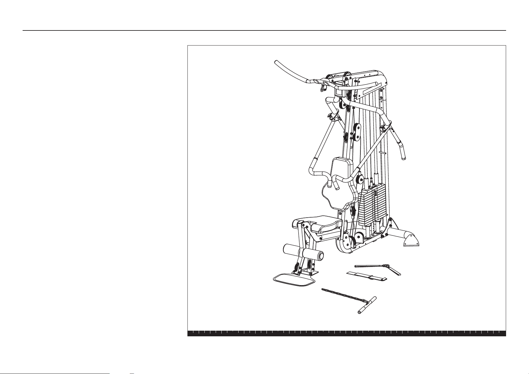
Open the Box
Open the Box
Use wire tie cutters to open the box.
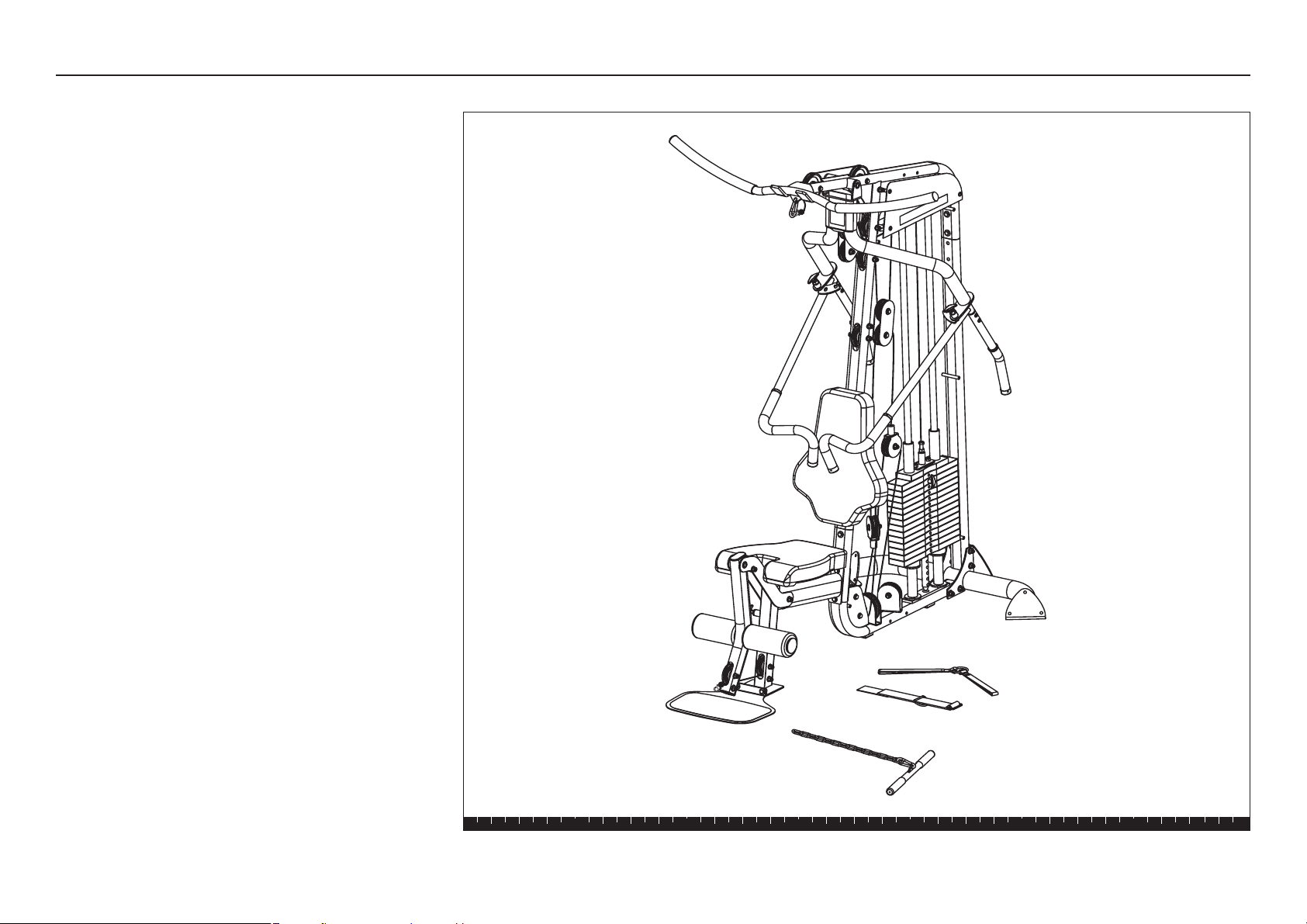
The illustration shows how the S3.15 will look when
you have completed its assembly. The callouts identify
specific pieces.
Important: Most fasteners are fitted to the frame or
pulleys, you will need to disassemble the fasteners
before proceeding with each step.
Main Base
Top Assembly
Rear Upright
Rear Crossbar
Main Upright
Leg Extension Arm
Weight Stack
Row Handle
Handlebars
Press Arm Assembly
Lat Bar
Leg Extension
Curl Bar
Ankle Strap
Triceps Strap
S3.15 Assembly and Maintenance Guide
page 8
1 2 3 4 5 6
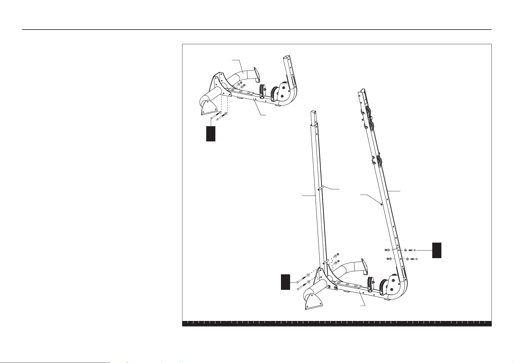
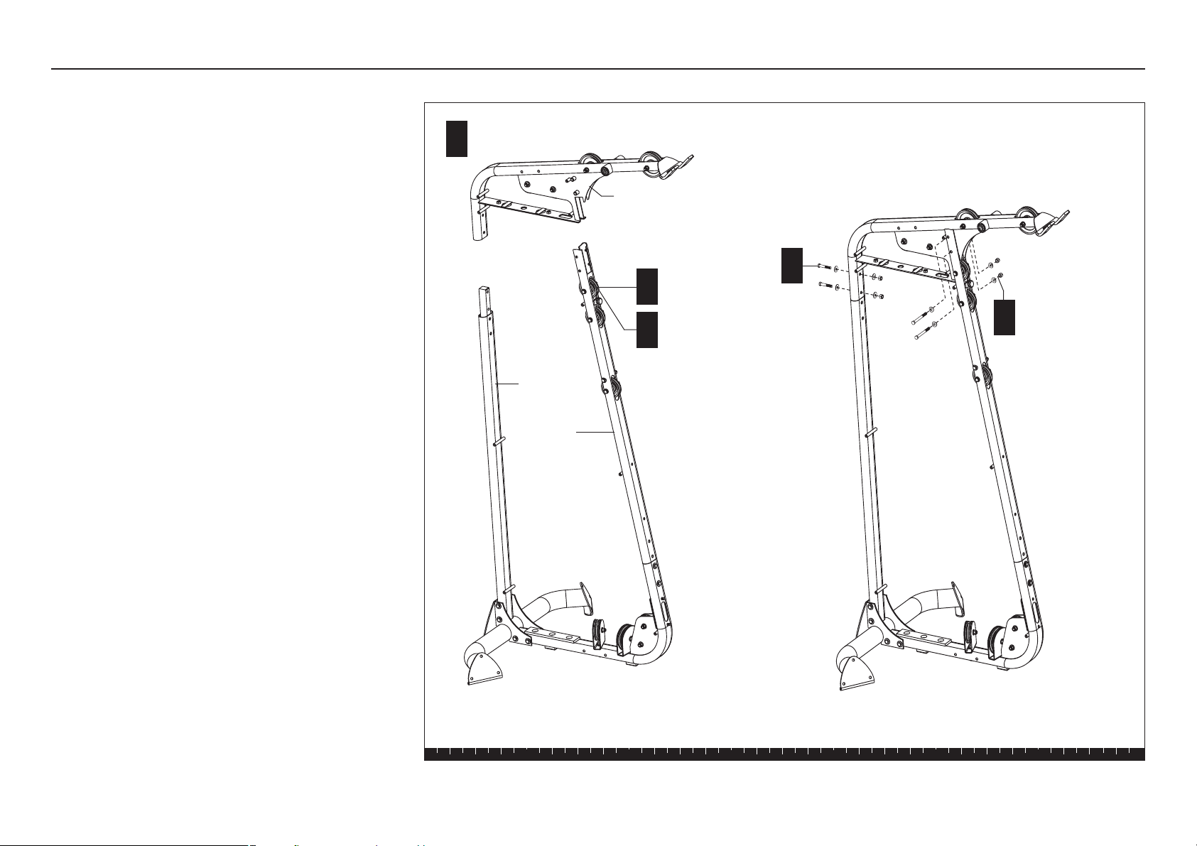
Step 1. Assemble Main Structure
1. Assemble Main Structure
A. Attach the Main Base to the Rear Crossbar using
two 4³⁄₄-inch hex head bolts
four flat washers
two locknuts
B. Install the Rear Upright to the Main Base using
two 4³⁄₄-inch hex head bolts
four flat washers
two locknuts
Note: Position the uprights so the Shroud mounts
face the center of the unit.
C. Attach the Main Upright to the Main Base
using
two 2¹⁄₄-inch hex head bolts
four flat washers
two locknuts
2 - 4³⁄₄" bolts
4 - washers
2 - locknuts
B
A
2 - 4³⁄₄" bolts
4 - washers
2 - locknuts
2 - 2¹⁄₄" bolts
4 - washers
2 - locknuts
C
Rear Crossbar
Main Base
Rear Upright
Main Upright
Main Base
Shroud
Mounts
S3.15 Assembly and Maintenance Guide
page 9
1 2 3 4 5 6
D. For ease of assembly, disassemble and remove
the top pulley and its fasteners on the Main
Upright.
E. Install the Top Beam on the Rear and Main
Uprights and reinstall the top pulley and fastener
assembly.
Note: If necessary, use a rubber mallet to align the
mounting holes.
F. Secure the Top Beam to the Rear Upright using
two 2¹⁄₄-inch hex head bolts
four flat washers
two locknuts
G. Secure the Top Beam to the Main Upright using
two 4-inch hex head bolts
four radius washers
two locknuts
Note: Make sure the radius washers lie flat against
the Main Upright before wrench tightening.
H. Wrench tighten all bolts. Start with the fasteners
that secure the Top Beam and follow the order of
the assembled steps in reverse.
J. Replace the top pulley and finger tighten the
fasteners.
Step 1. Assemble Main Structure, continued
E
F
Align Top Beam with
uprights.
Main
Upright
Rear
Upright
2 - 2¹⁄₄" bolts
4 - washers
2 - locknuts
G
2 - 4" bolts
4 - radius washers
2 - locknuts
Top Beam
D
J
S3.15 Assembly and Maintenance Guide
page 10
1 2 3 4 5 6
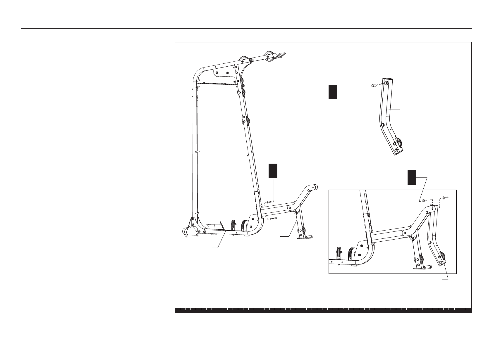
2. Assemble Leg Extension
A. Attach the Leg Extension to the Main Base using
two 2½-inch bolts
two spring washers
Wrench tighten.
B. Insert the 2-inch threaded shaft into the Leg
Extension Arm.
C. Attach the Leg Extension Arm to the Leg
Extension using
two ¹⁄₂-inch x ¾-inch buttonhead bolts
two flat washers
Wrench tighten using the 8mm hex keys.
Step 2. Assemble Leg Extension
A
2 - 2½" bolts
2 - spring washers
B
C
2 - ¹⁄₂" x ¾-inch
buttonhead bolts
2 - washers
Threaded
Shaft
Main Base
Leg Extension Arm
Leg Extension Arm
Leg
Extension
S3.15 Assembly and Maintenance Guide
page 11
1 2 3 4 5 6
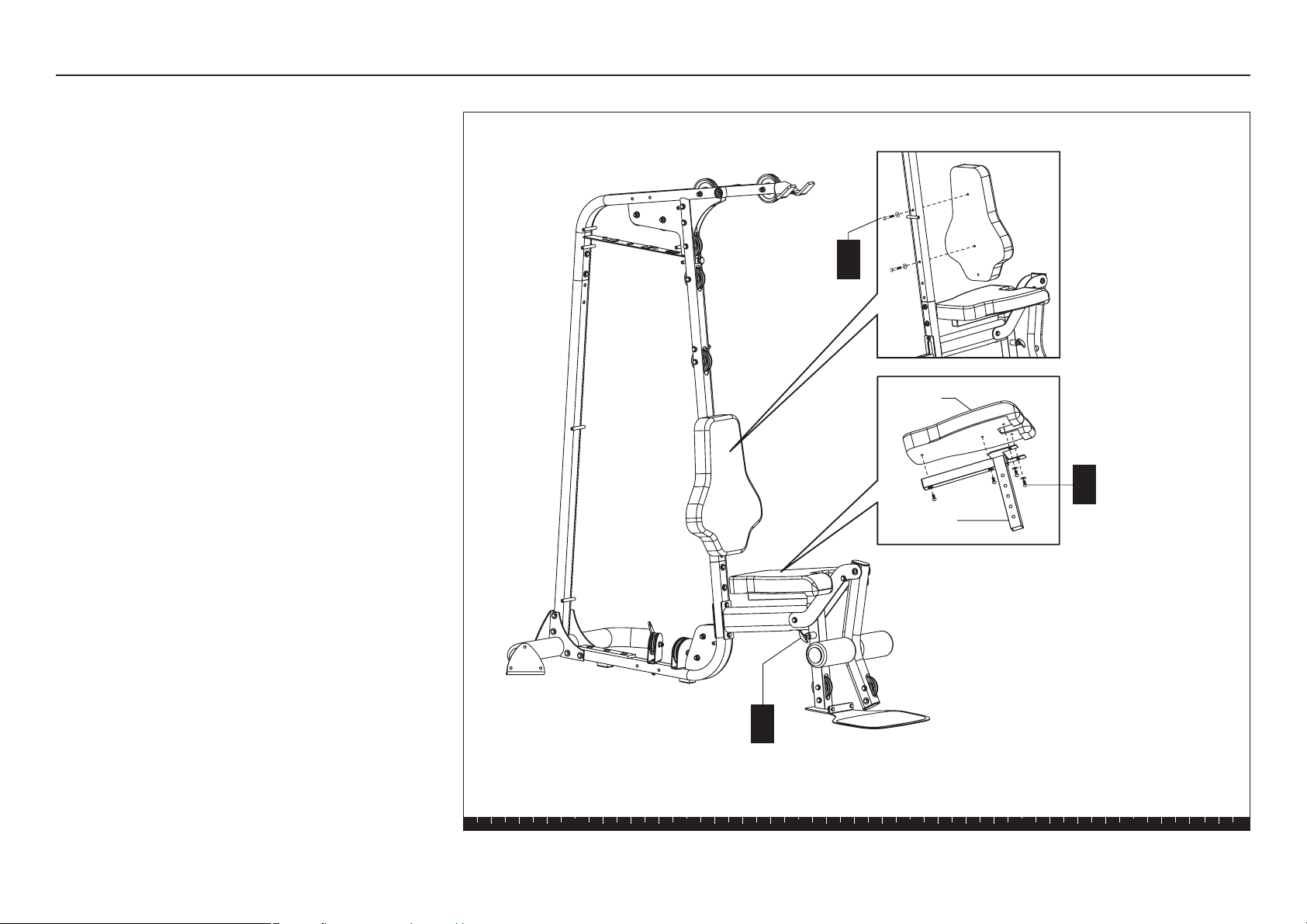
3. Install Seat and Rollers
A. Attach the Seat Pad to the Seat Stem using
four 1-inch zinc buttonhead bolts
two zinc flat washers
Wrench tighten using a 6mm hex key.
B. Insert the Seat Stem into the Seat Upright
Assembly. Pull out the seat adjustment pin to
insert the stem. Place the Seat Stem at its lowest
position.
C. Attach the Back Pad to the Main Upright using
two 2½-inch hex head bolts
two flat washers
Wrench tighten.
Step 3. Install Seat and Rollers
A
4 - 1" zinc
buttonhead bolts
2 - zinc washers
B
C
2 - 2½" bolts
2 - washers
Pull out the seat
adjustment pin to
insert stem.
Back
Pad
Seat Stem
Seat Pad
S3.15 Assembly and Maintenance Guide
page 12
1 2 3 4 5 6
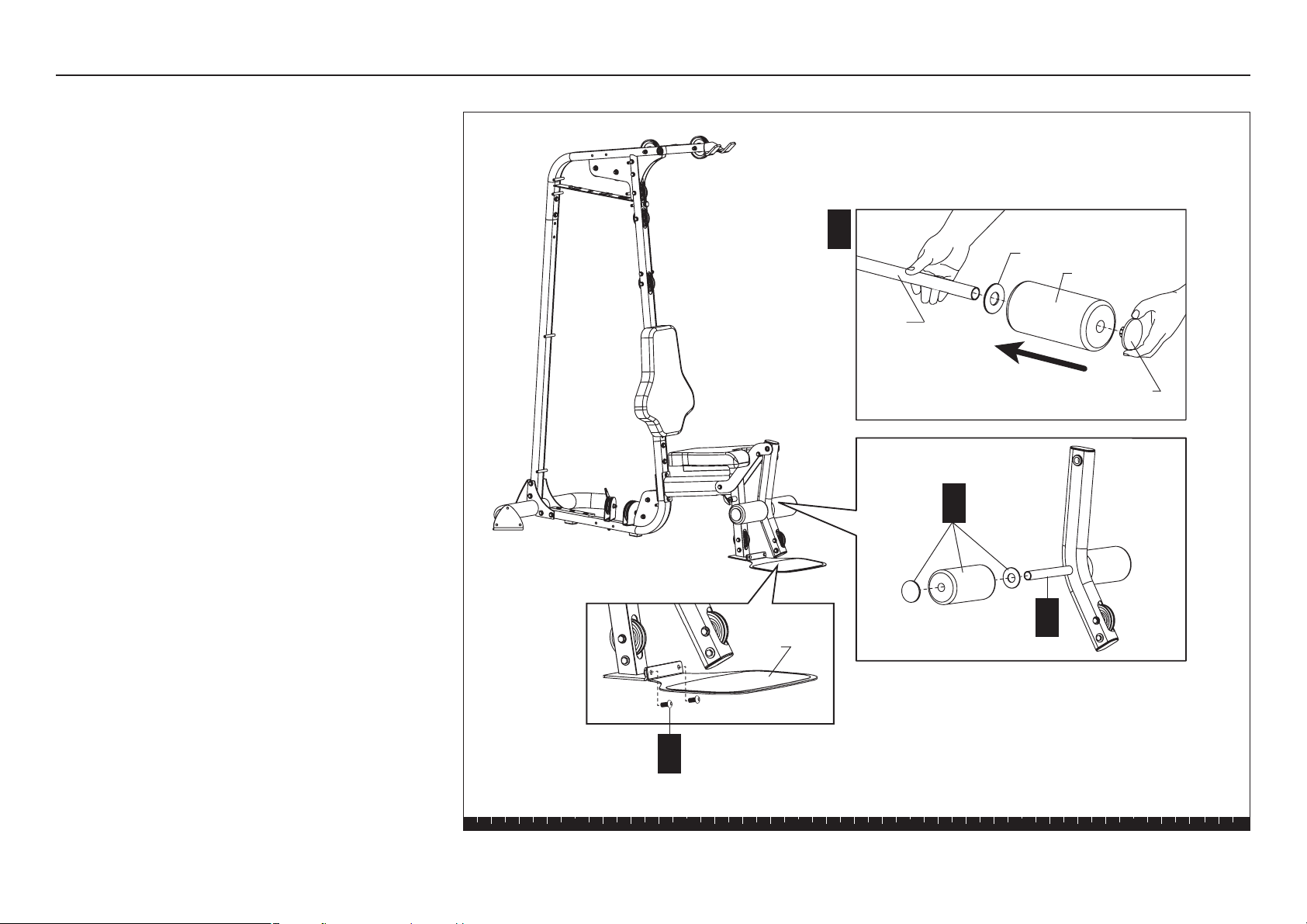
D. Slide a Plastic Washer and a Roller Pad onto one
end of a Roller Pad Rod. Insert one Mushroom
Cap to plug the end hole. If necessary, pound the
Mushroom Cap in place using the rubber mallet.
E. Insert the Roller Pad Rod through the hole in the
Leg Extension Arm.
F. Slide the remaining Plastic Washer and Roller Pad
on the other end of the Roller Pad Rod. Insert one
Mushroom Cap to plug the end hole. If necessary,
pound the Mushroom Cap in place using the
rubber mallet.
G. Attach the Floor Plate using
two ³⁄₄-inch buttonhead bolts
Wrench tighten using a 6mm hex key.
D
Roller Pad
Plastic Washer
E
Roller
Pad Rod
Mushroom Cap
F
G
2 - ³⁄₄" buttonhead bolts
Floor
Plate
Step 3. Install Seat and Rollers, continued
S3.15 Assembly and Maintenance Guide
page 13
1 2 3 4 5 6
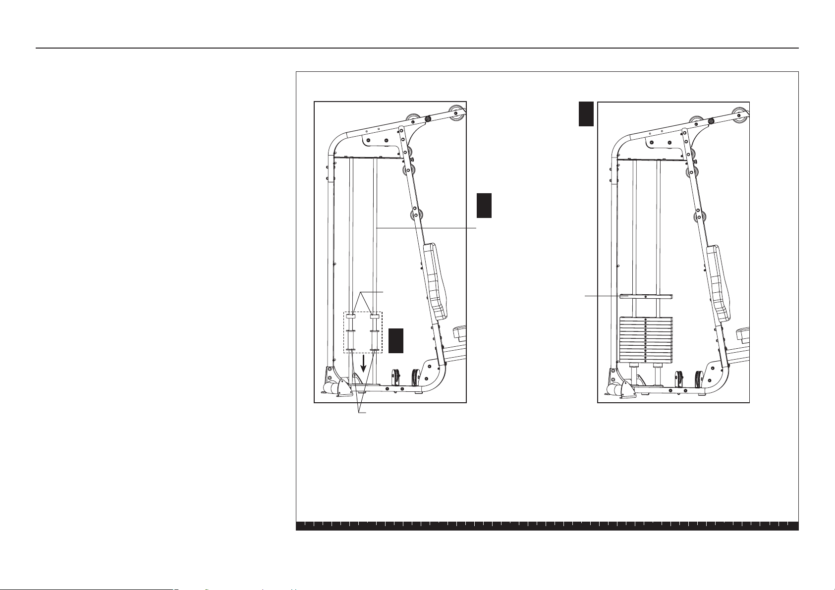
Step 4. Assemble Weight Stack
4. Assemble Weight Stack
Important: Obtain adult assistance before installing
the Guide Rods and Weights.
A. Place the Guide Rods into the two outside holes in
the Main Base.
CAUTION: The lubricant on the Guide Rods can
stain clothes. Wear proper attire when working
with or lubricating the Guide Rods.
B. Place one Guide Rod Spacer and one Weight
Cushion on each Guide Rod and allow it to slide
down and rest on the Main Base.
Note: Guide Rod Spacers do not need to be
installed if the Heavy Stack Option is purchased
through your dealer.
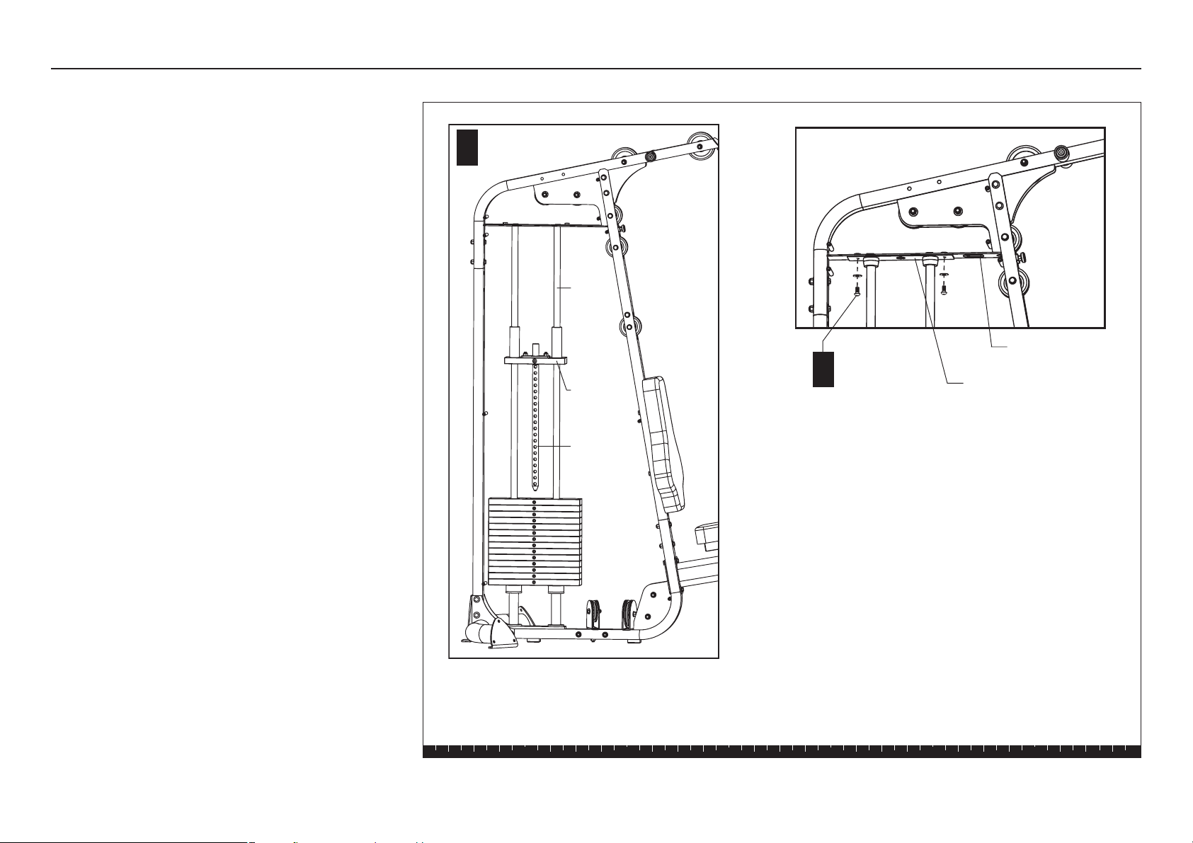
C. Add the 10-lb weights. For ease of weight pin
placement and use, orient the curve on the weight
plate to the desired side of the unit. Position the
weight plate so the plastic bushing is on top and
hold your finger over the plastic bushing to prevent
it from popping out.
CAUTION: The weights are heavy! Handle
the weights carefully so as not to drop them
or injure yourself. Pick up and place one
weight at a time on the Guide Rods. Do not
angle the Guide Rods to such a degree that
they dislodge the Guide Rod Spacers or
Weight Cushions. Have someone hold the
Guide Rods in place while you slide the
weights on the stack.
A
B
C
Guide Rod
Weight
Weight
Cushions
Guide Rod Spacers
(Do not install spacers if you
purchased the Heavy Stack Option.)
S3.15 Assembly and Maintenance Guide
page 14
1 2 3 4 5 6
D. Orient the hole in the Top Cap Weight with the
curve in the weight plates. Place the Top Cap
Weight onto the Guide Rods and slide the Selector
Stem into the weight stack.
E. Slide the Guide Rod Bracket onto the Guide Rods
and secure it to the Upper Frame Crosspiece using
two ³⁄₄-inch buttonhead bolts
two flat washers
Wrench tighten.
D
Step 4. Assemble Weight Stack, continued
Top Cap
Weight
Guide
Rod
Selector
Stem
Upper Frame
Crosspiece
Guide Rod Bracket
E
2 - ¾" buttonhead
bolts
2 - washers
S3.15 Assembly and Maintenance Guide
page 15
1 2 3 4 5 6
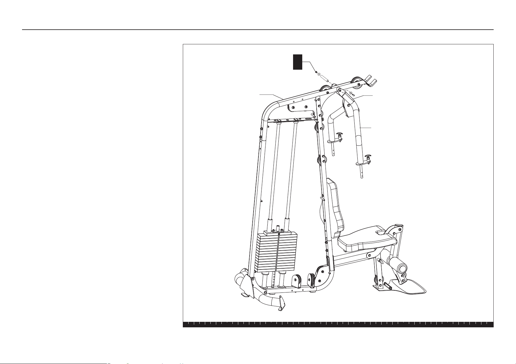
5. Assemble Press Arm
Important: Obtain adult assistance to attach the Press
Arm Assembly.
A. Attach the Press Arm Assembly, with the label
facing out, to the Top Beam using
one threaded shaft
two 1-inch buttonhead bolts
two zinc flat washers
Wrench tighten.
Step 5. Assemble Press Arm
A
1 - threaded shaft
2 - 1" buttonhead bolts
2 - zinc washers
Top Beam
Press Arm
Assembly
Label on Press Arm Assembly
S3.15 Assembly and Maintenance Guide
page 16
1 2 3 4 5 6
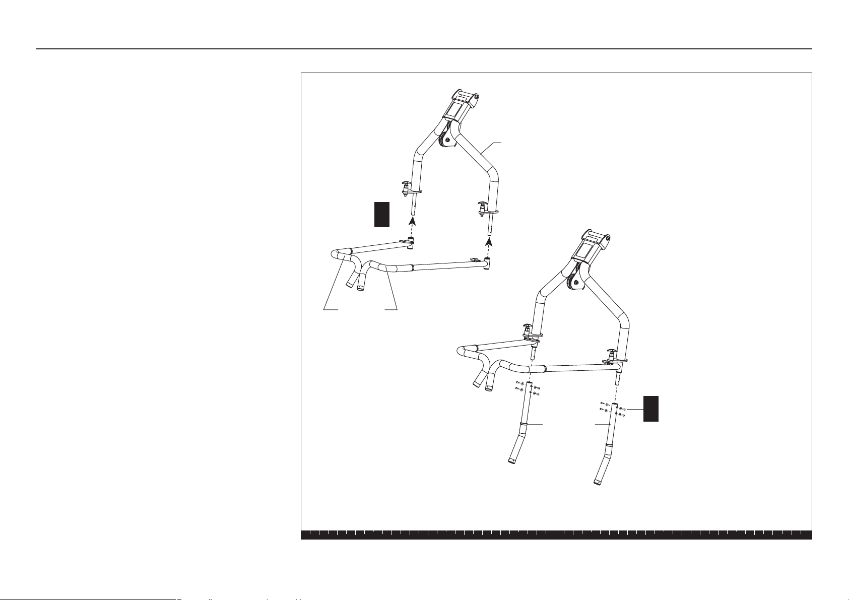
B. Slide the Handlebars in place on the Press Arm.
Handlebars curve inward. Review the illustration
for correct handlebar placement.
C. Attach the Row Handles using
eight ¼ x ½-inch buttonhead screws
eight radius washers
Note: Make sure the radius washers lie flat against
the Row Handle before wrench tightening.
D. Wrench tighten the screws using the 5mm hex
keys.
Step 5. Assemble Press Arm, continued
B
8 - ¼ x ½" buttonhead screws
8 - radius washers
C
Press Arm Assembly
Handlebars
Row Handles
S3.15 Assembly and Maintenance Guide
page 17
1 2 3 4 5 6
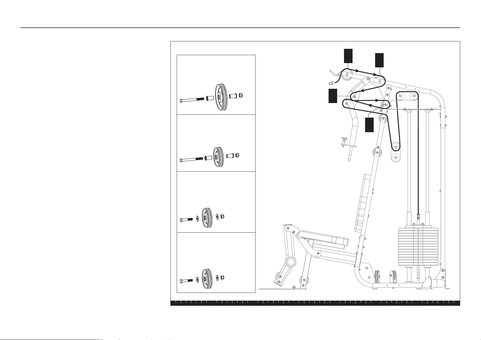
Step 6. Install Main Cable
6. Install Main Cable
Note: All pulleys are installed in the frame
assemblies. As you begin each new step, remove
the fasteners and pulley. Feed the cable around
the pulley as shown, and then replace the
fasteners and finger tighten. Wrench tighten all
pulley fasteners once you have completed the
installation of each cable assembly.
A. Start at the Top Beam and feed the threaded end
of Main Cable 130197 over one 4½-inch pulley.
Attach the pulley to the Top Beam using
one 4-inch hex head bolt
two 1¹⁄₄-inch shoulder spacers
one locknut
B. Feed the cable over the second 4½-inch pulley.
Attach the pulley to the Top Beam using
one 4-inch hex head bolt
two 1¹⁄₄-inch shoulder spacers
one locknut
C. Feed the cable over the upper 3½-inch pulley
located in the Press Arm assembly. Attach the
pulley to the Press Arm assembly using
one 2-inch zinc hex head bolt
two zinc flat washers
one zinc locknut
D. Feed the cable over the upper 3½-inch pulley
located in the Main Upright. Attach the pulley to the
Main Upright using
one 4-inch hex head bolt
two 1¹⁄₄-inch shoulder spacers
one locknut
A
B
C
D
4½-inch Pulley
1 - bolt
2 - shoulder spacers
1 - locknut
3½-inch Pulley (used on gray
painted parts)
1 - bolt
2 - shoulder spacers
1 - locknut
Pulley assemblies
3½-inch Pulley (used on
titanium parts)
1 - zinc bolt
2 - zinc washers
1 - zinc locknut
3½-inch Pulley (used on gray
painted parts)
1 - bolt
2 - washers
1 - locknut
S3.15 Assembly and Maintenance Guide
page 18
1 2 3 4 5 6
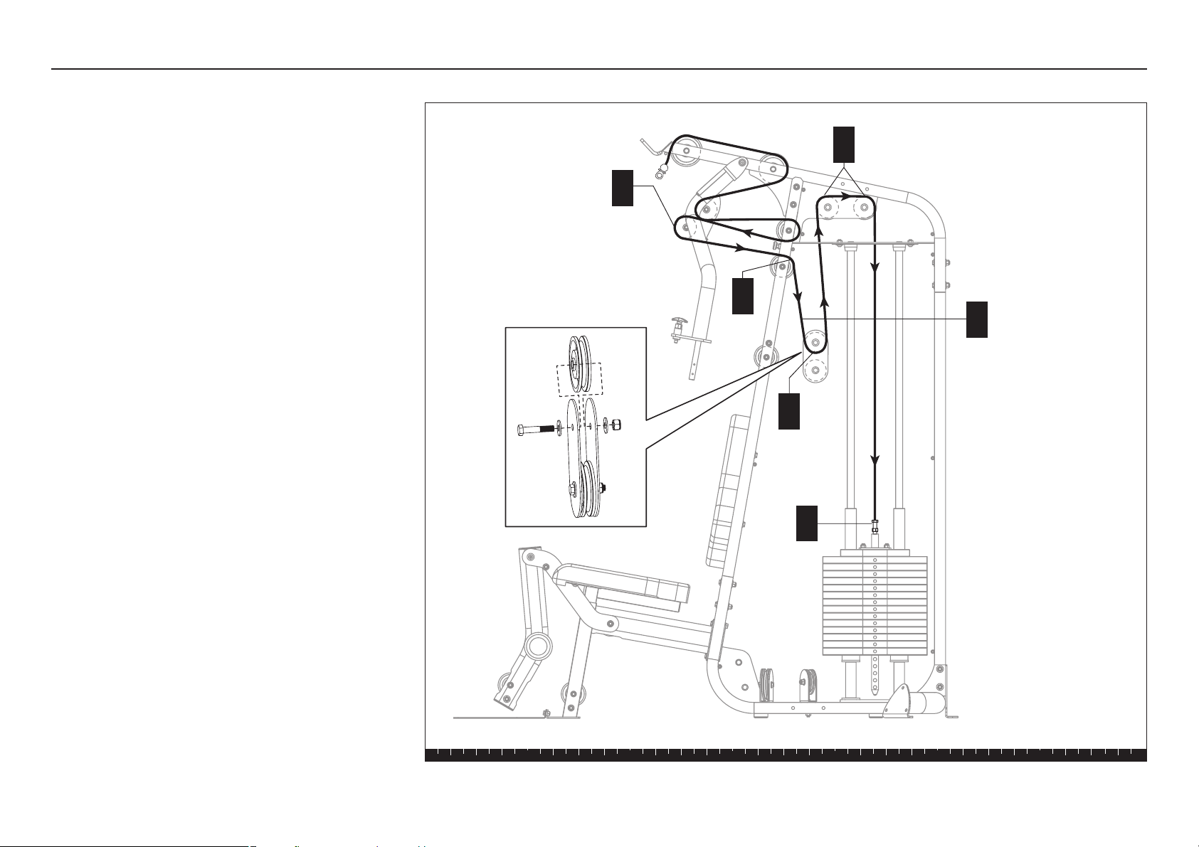
E. Feed the cable over the lower 3½-inch pulley
located in the Press Arm assembly. Attach the
pulley to the Press Arm assembly using
one 2-inch zinc hex head bolt
two zinc flat washers
one zinc locknut
F. Feed the cable over the upper 3½-inch pulley
located in the Main Upright. Attach the pulley to the
Main Upright using
one 4-inch hex head bolt
two 1¹⁄₄-inch shoulder spacers
one locknut
G. Pull the slack out of the Main Cable so the ball end
of the cable rests against the Lat Bar Holder.
H. Disassemble the upper pulley in the Double
Floating Pulley as shown. Feed the cable around
the 3½-inch pulley and reattach it using
one 2-inch zinc hex head bolt
two zinc flat washers
one zinc locknut
J. Feed the cable through the hole in the Upper
Frame Crosspiece and over the two 3½-inch
pulleys attached to the Top Beam assembly.
Reattach the pulleys to the assembly using
two 2-inch hex head bolts
four flat washers
two locknuts
K. Feed the cable down through the hole in the Upper
Frame Crosspiece and attach the threaded end of
the cable into the Selector Stem. Continue turning
the screw three to four full turns to secure the
threads inside the Selector Stem.
L. Wrench tighten all pulley fasteners.
Important: Do not tighten the jam nut on the
threaded end of the cable or the Double Floating
Pulley fasteners, at this time.
Step 6. Install Main Cable, continued
H
K
J
E
F
G
Double Floating Pulley
Assembly
1 - 2" zinc bolt
2 - zinc washers
1 - zinc locknut
Pull slack and place the
excess cable on the floor
while you assemble the
Double Floating Pulley.
2 - bolts
4 - washers
2 - locknuts
1 - 2" zinc bolt
2 - zinc washers
1 - zinc locknut
S3.15 Assembly and Maintenance Guide
page 19
1 2 3 4 5 6
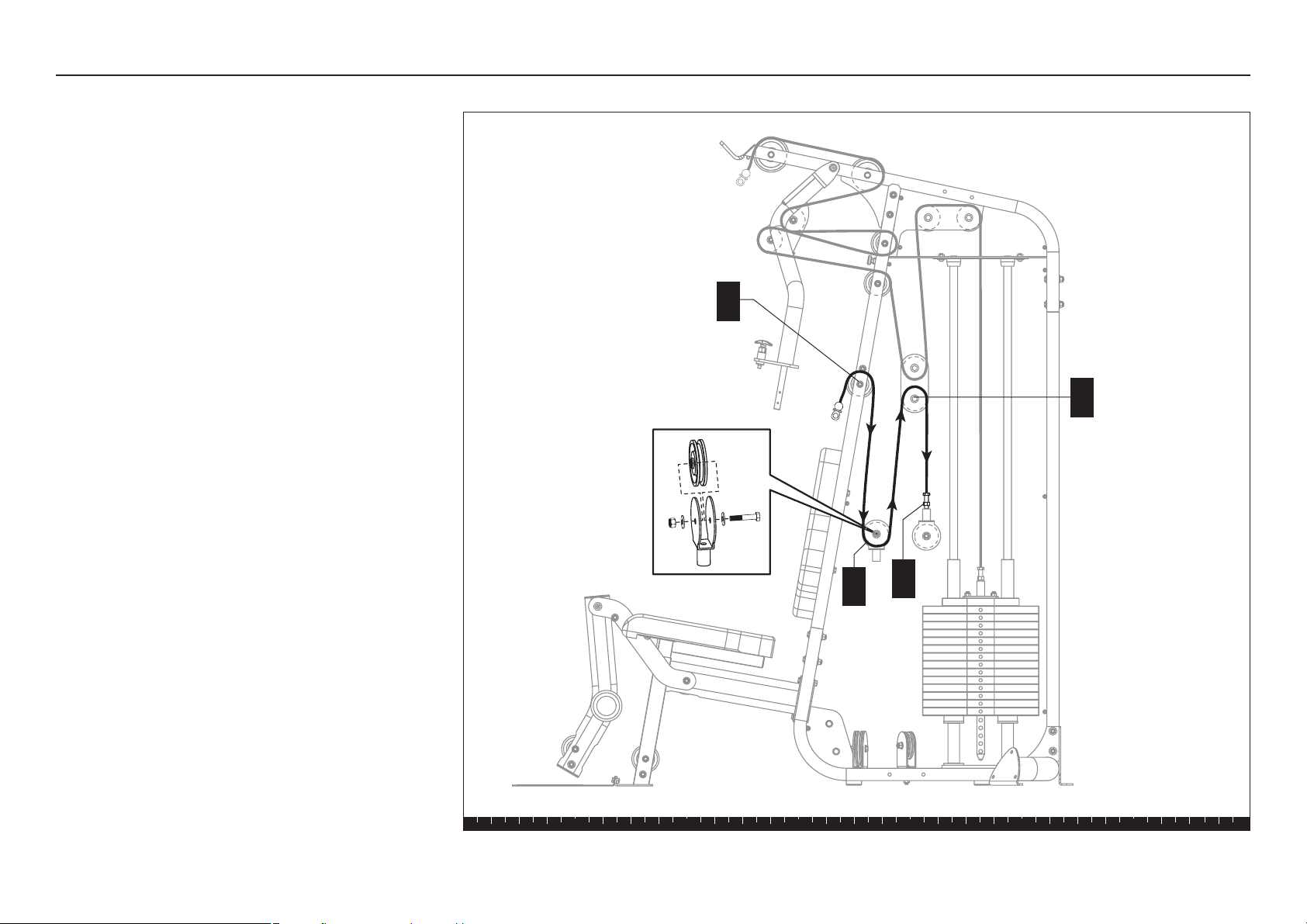
7. Install Ab Cable and Floating
Pulleys
A. Start at the center pulley on the Main Upright.
Feed the threaded end of Ab Cable 130196
through the opening and over one 3½-inch pulley.
Attach the pulley to the Main Upright using
one 4-inch hex head bolt
two flat washers
one locknut
B. Disassemble the 3½-inch pulley located inside the
Single Floating Pulley. Feed the cable around the
pulley and reattach the pulley using
one 1¹⁄₂-inch zinc hex head bolt
two zinc washers
one thin zinc locknut
Wrench tighten.
C. Disassemble the lower portion of the Double
Floating Pulley. Feed the cable around the lower
pulley and reattach it using
one 2-inch zinc hex head bolt
two zinc flat washers
one zinc locknut
D. Attach the threaded end of the cable to a Single
Floating Pulley. Continue turning the screw three to
four full turns to secure it inside the floating pulley
housing.
F. Remove any twists in the cables, and then wrench
tighten all pulley fasteners.
Step 7. Install Ab Cable and Floating Pulleys
A
B
C
D
Single Floating
Pulley Assembly
1 - 1½" zinc bolt
2 - zinc washers
1 - zinc locknut
1 - 4" bolt
2 - washers
1 - locknut
1 - 2" zinc bolt
2 - zinc washers
1 - zinc locknut
S3.15 Assembly and Maintenance Guide
page 20
1 2 3 4 5 6
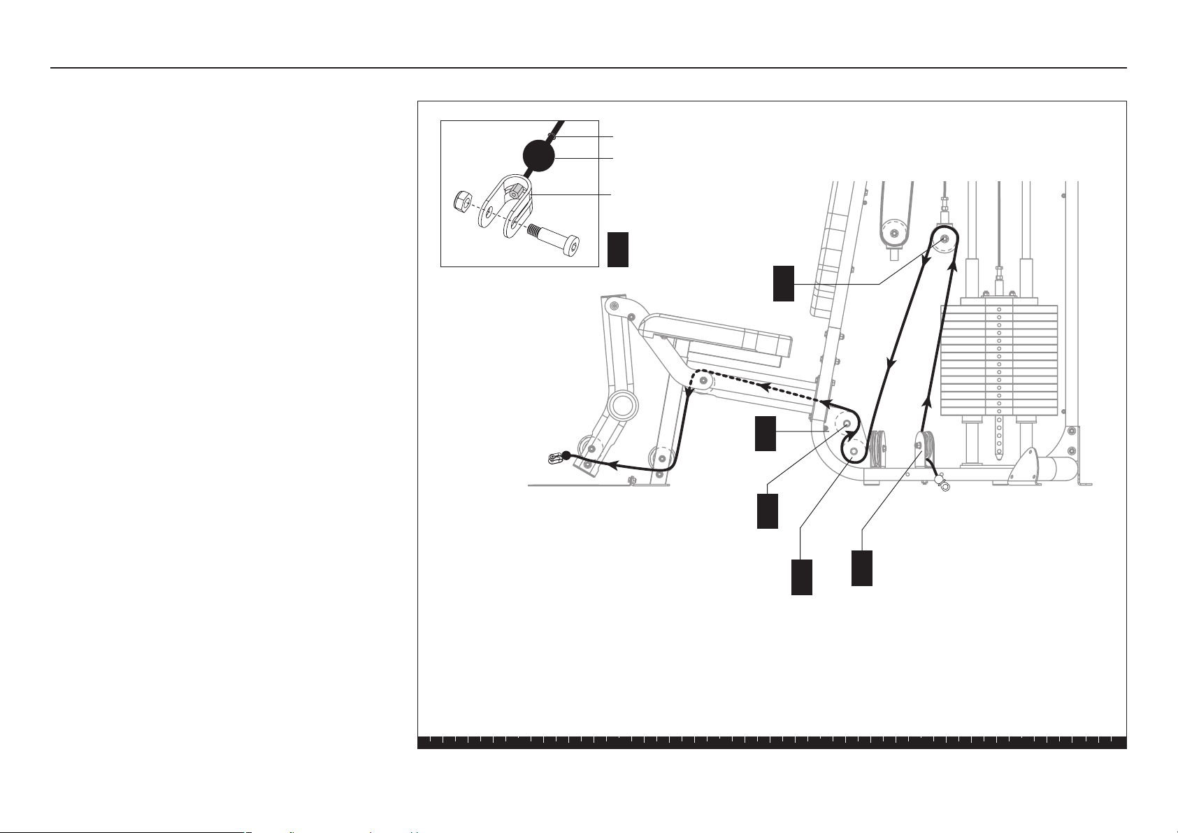
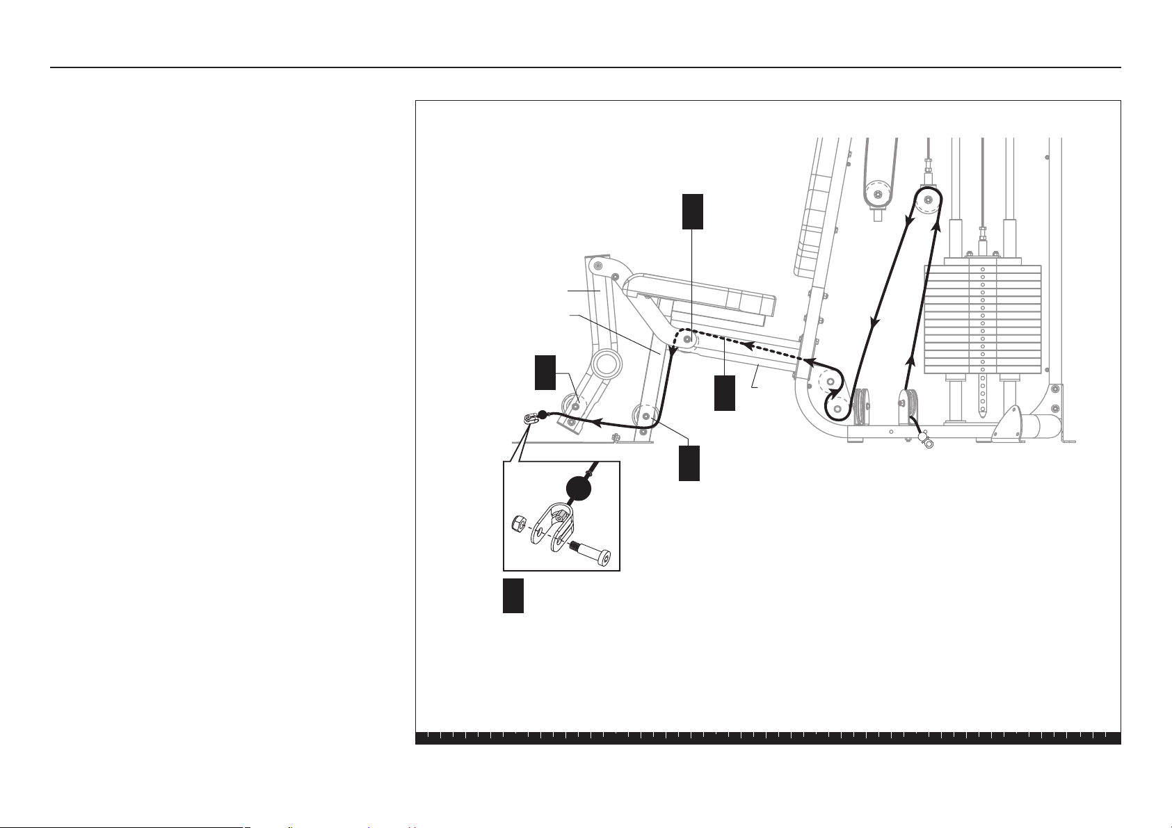
8. Install Leg Extension Cable
A. Before feeding the cable through the pulley
assemblies, remove the U-bracket assembly, cable
stop ball and rubber washer at the end of the Leg
Extension Cable 130198.
B. Start at the Pivoting Bracket attached to the
Main Base. Feed the end of the cable beneath the
3½-inch pulley.
C. Feed the cable through the Single Floating Pulley
as shown.
D. Disassemble the upper 3½-inch pulley located
inside the Gusset which is welded to the Base
Frame.
E. Feed the cable under the lower pulley.
F. Loop the cable over the upper 3½-inch pulley and
secure it to the Gusset using
one 2¼-inch bolt
two flat washers
one locknut
Step 8. Install Leg Extension Cable
Gusset
F
E
1 - 2¼" bolt
2 - washers
1 - locknut
D
C
B
A
Rubber Washer
Cable Stop Ball
U-bracket
S3.15 Assembly and Maintenance Guide
page 21
1 2 3 4 5 6
1 - rubber washer
1 - cable stop ball
1 - U-bracket
1 - 1¼" bolt
1 - locknut
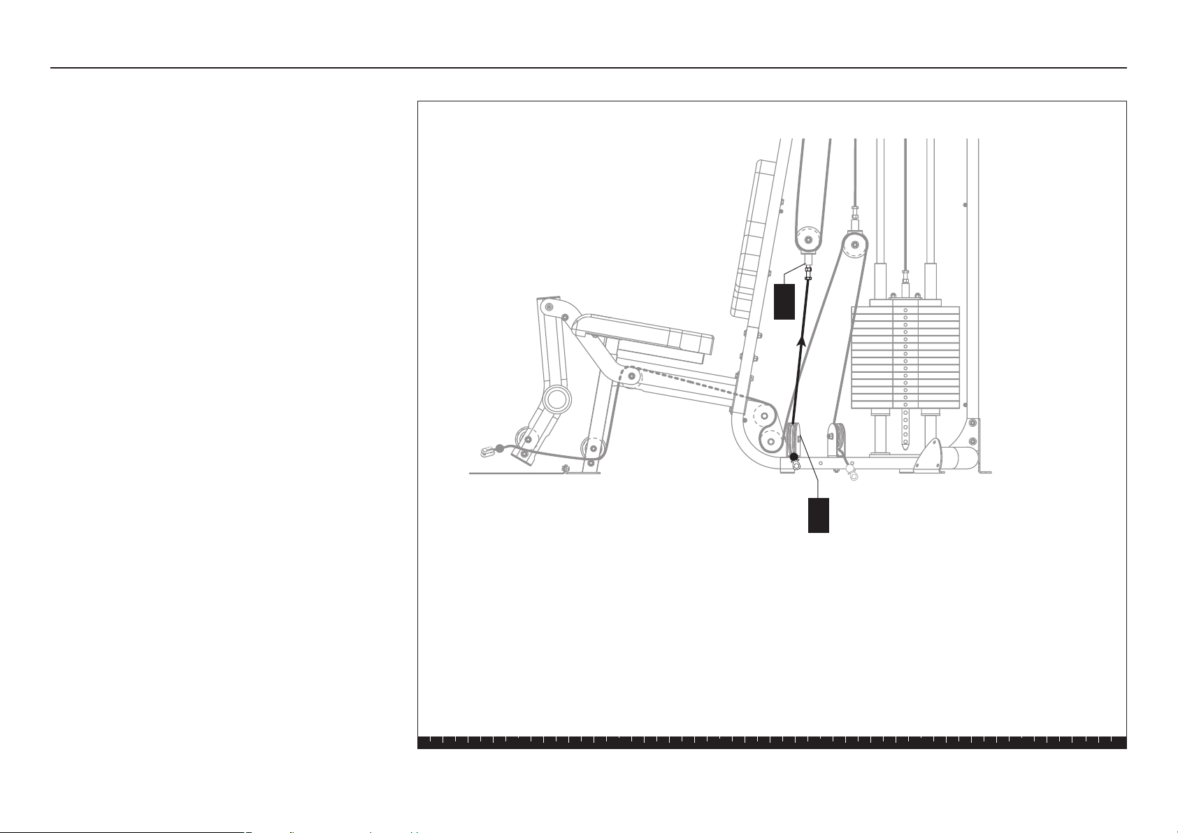
G. Continue to feed the cable through the Seat Frame.
H. Disassemble the 3½-inch pulley located beneath
the seat. Feed the cable over the pulley and
reattach the pulley to the Seat Frame using
one 3-inch hex head bolt
two ³⁄₄-inch shoulder spacers
one locknut
J. Feed the cable under the lower 3½-inch pulley
located on the Seat Stem.
K. Feed the cable through the opening and under the
3½-inch pulley located in the Leg Extension Arm.
L. Replace the rubber washer and cable stop ball
onto the end of the cable and insert the end of the
cable into the U-bracket. Complete the U-bracket
assembly using
one 1¼-inch shoulder bolt
one locknut
M. Wrench tighten all pulley fasteners.
Step 8. Install Leg Extension Cable, continued
J
H
1 - 3" bolt
2 - ³⁄₄" shoulder spacers
1 - locknut
Seat
Frame
Leg Extension Arm
Seat Stem
L
K
G
S3.15 Assembly and Maintenance Guide
page 22
1 2 3 4 5 6
9. Install Leg Press Option
Cable Connection
Note: If you plan to attach the Multi-Hip or Leg Press
Options, make sure that cable ends are on opposite
sides of the Main Base. Do not position the cable ends
as shown in this illustration.
A. Start at the Base Frame and feed the threaded end
of Cable 130195 under the 3½-inch pulley. Attach
the pulley to its base frame bracket using
one 2-inch hex head bolt
one flat washer
Wrench tighten.
B. Attach the threaded end of the cable to the Single
Floating Pulley. Continue turning the screw at least
three to four full turns to secure it inside the
floating pulley housing.
Step 9. Install Leg Press Option Cable Connection
B
A
1 - 2" zinc bolt
1 - washer
S3.15 Assembly and Maintenance Guide
page 23
1 2 3 4 5 6
10. Attach Upper Shrouds
A. Attach the Upper Shrouds to the Top Beam using
six 1¾-inch zinc buttonhead bolts
six black plastic washers
six tapered spacers
Wrench tighten.
A
6 - 1¾" zinc buttonhead bolts
6 - black plastic washers
6 - tapered spacers
Step 10. Attach Upper Shrouds
S3.15 Assembly and Maintenance Guide
page 24
1 2 3 4 5 6
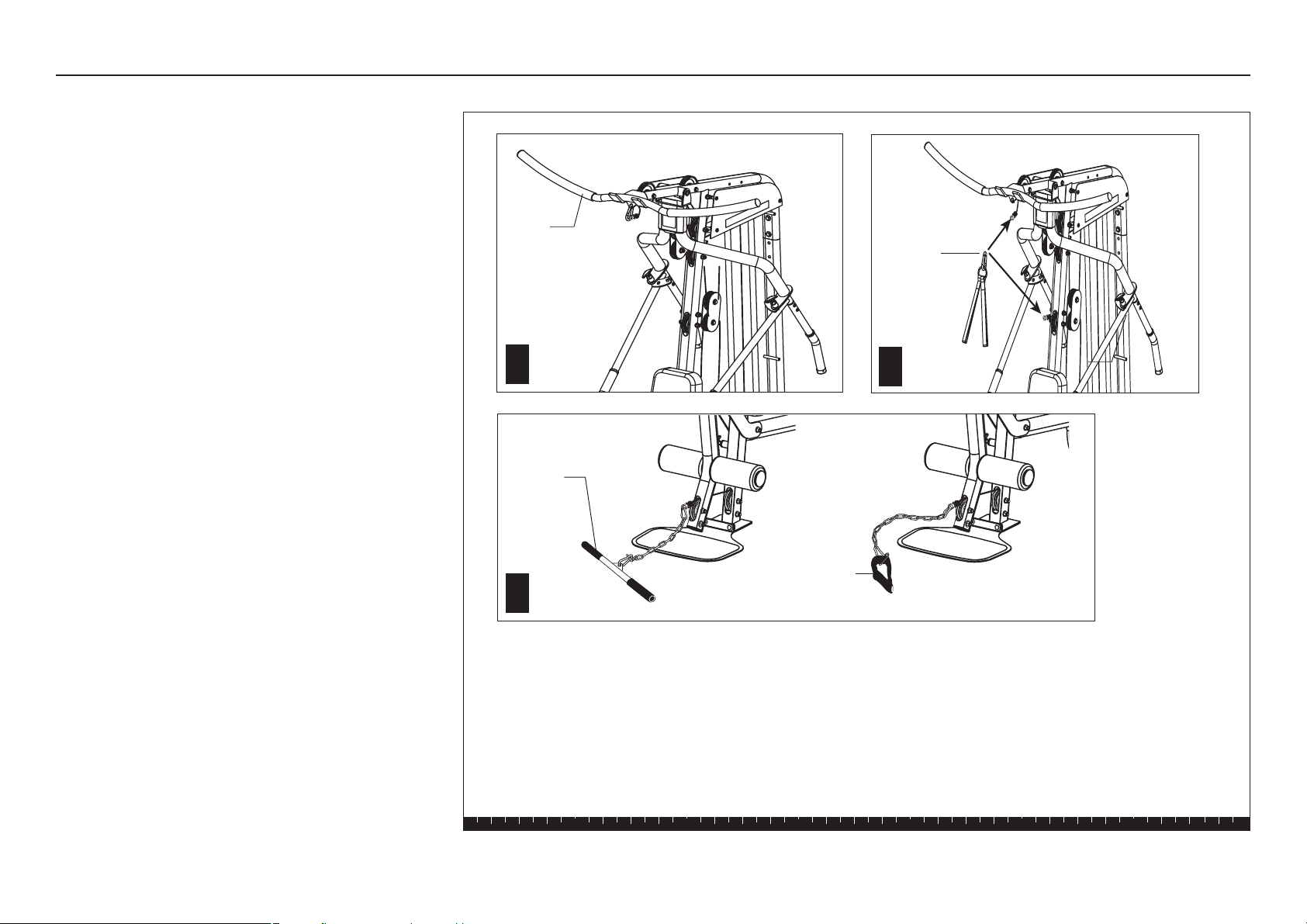
11. Attach Accessories
A. At the end of the Top Beam, attach the Lat Bar to
the Main Cable using a spring clip.
Note: The two small hooks at the end of the Top
Beam can be used to store the Lat Bar when it’s
not in use.
B. Install the Triceps Straps to the Ab Cable using the
spring clip.
To vary your exercise routine, you can replace the
Lat Bar and attach the Triceps Straps to the Main
Cable.
C. Attach the Curl Bar to the Leg Extension Cable
using the short piece of chain and two spring clips
(installed at each end of the chain).
To work out leg muscle groups, you can attach a
Soft Ankle Strap, to the end of the cable, instead of
the curl bar.
D. For aesthetics, insert plastic plugs into the unused
mounting holes in the Top Beam, Main Base, and
Rear Crossbar.
Curl
Bar
Ankle
Strap
Lat
Bar
Step 11. Attach Accessories
Triceps
Strap
A
B
C
S3.15 Assembly and Maintenance Guide
page 25
1 2 3 4 5 6
1
3
2
4
5
6
7
8
9
10
11
12
13
14
15
1
3
2
4
5
6
7
8
9
10
11
12
13
14
15
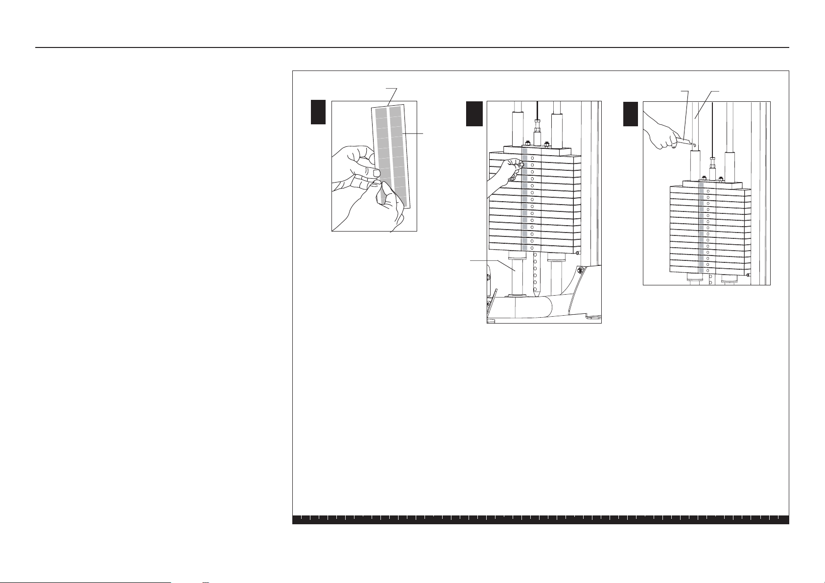
12. Apply Weight Decals and
Lubricant
A. Peel the Weight Label off the Weight Label Strip.
B. Peel the backing off the Weight Label to expose
the adhesive and place a label on each Weight
Plate, starting with the Top Cap Weight. The
recommended location of the label is toward the
rear of the unit (refer to the illustration).
C. Apply one tube of lubricant to each Guide Rod.
CAUTION: The lubricant can stain clothes. Wear
proper attire when lubricating the Guide Rods.
This completes the assembly of your S3.15 Strength-
Training Fitness Equipment. Before exercising on the
S3.15, adjust the cable tension. Refer to
Cable
Adjustments and Maintenance
.
Note: If you have purchased optional equipment, refer
to the
Assembly Instructions
accompanying the option.
Step 12. Apply Weight Decals and Lubricant
C
Lubricant Guide Rod
A
B
Weight Label Strip
Weight
Label
11
12
13
14
15
16
17
18
19
20
1
2
3
4
5
6
7
8
9
10
Guide Rod Spacers*
*Heavy Stack Option not shown.
S3.15 Assembly and Maintenance Guide
page 26
1 2 3 4 5 6
4
Cable Adjustments
and Maintenance
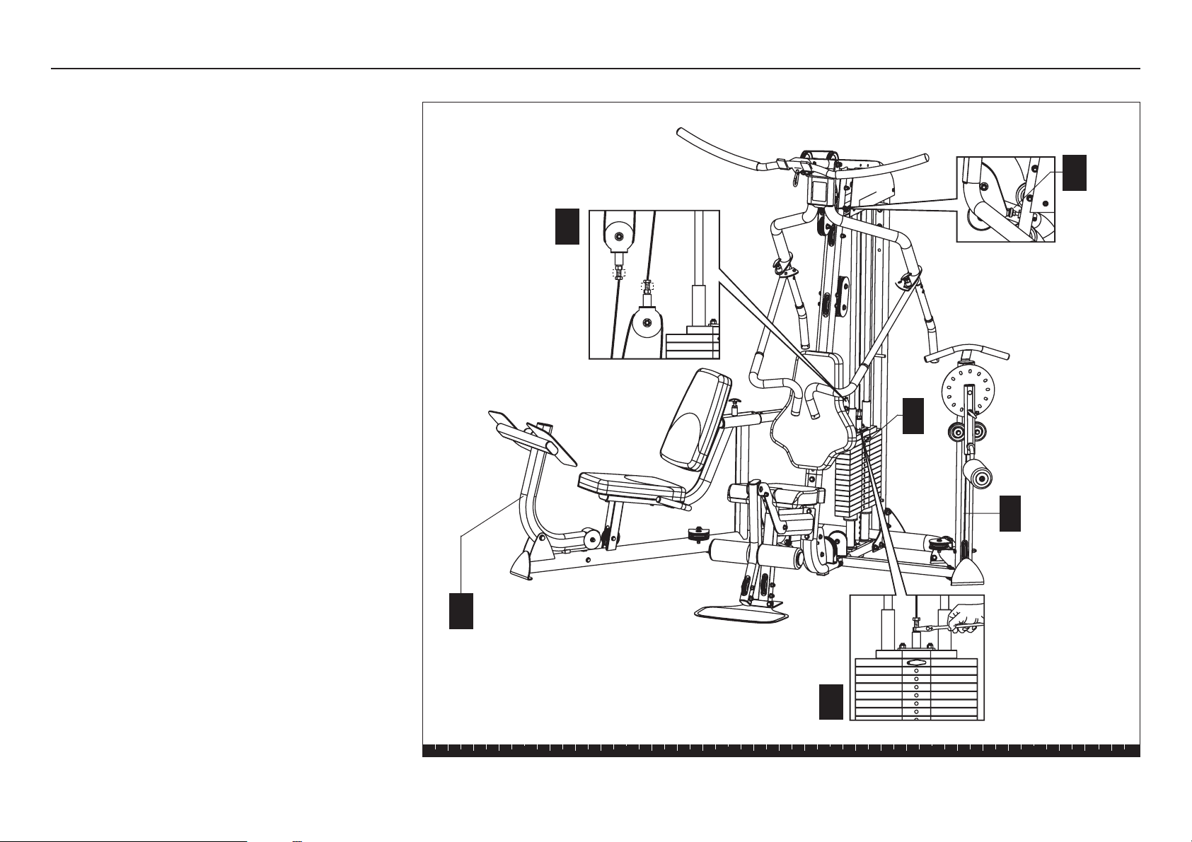
Cable Adjustments and Maintenance
When the S3.15 is completely assembled, you need to
check the cables for proper tension. Obvious signs that
cable problems exist include:
✔ Top Cap Weight does not rest squarely on the top
weight of the Weight Stack.
✔ Cable rubs the inside edges of the pulleys.
✔ Excess slack exists in the cable.
✔ Weight Pin cannot be easily inserted in or
removed from each hole in the Weight Stack.
CAUTION: Take the time to perform the following
steps. If the cables do not have the proper tension
you could void the Precor Limited Warranty.
S3.15 Assembly and Maintenance Guide
page 27
1 2 3 4 5 6
Cable Adjustments and Maintenance, continued
1. Cable Tension
If you experience any of these cable problems, take
the following steps to reduce tension on the cables:
A. Place the Weight Pin in the Top Weight.
B. Place the Leg Press Support Arm in the upright
(non-extended) position.
C. Position the Multi-Hip Pivot Arm so the cable
remains centered between the two pulleys on the
Multi-Hip Upright.
D. Check that the Press Arm rests lightly on the
Bumper Pad and is positioned so it causes minimal
tension in the cable. If necessary, rotate the
Bumper Pad.
E. Adjust the threaded ends on the Single Floating
Pulleys so the amount showing is the same on
both pulleys. Retighten the jam nuts.
Note: You may need to loosen the jam nuts before
making adjustments.
F. Adjust the Weight Stack threaded end. Retighten
the jam nuts.
CAUTION: For safety reasons, always make
sure to turn the screw three to four full turns
so that the threads are engaged inside the
Selector Stem or Floating Pulleys before
tightening the jam nuts.
C
A
B
Leg Support Arm in
upright position.
Align cable.
Center it between
the two pulleys.
D
E
F
S3.15 Assembly and Maintenance Guide
page 28
1 2 3 4 5 6
Cable Adjustments and Maintenance, continued
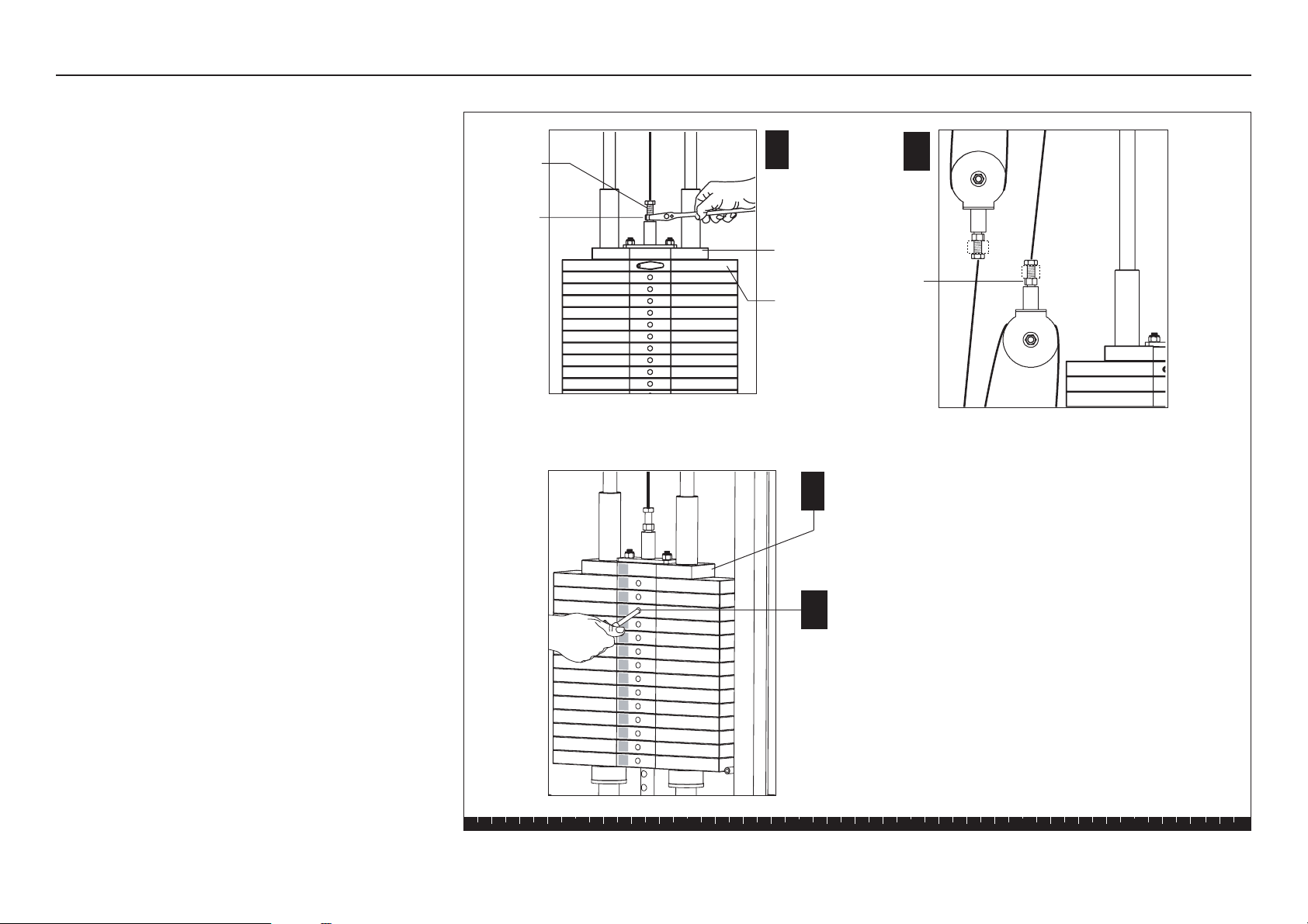
2. Cable Adjustments
You may need to adjust the cables after installation and
periodically thereafter. If the cables remain slack after
you have followed the steps found in
Cable Tension
,
perform the following:
A. Loosen the jam nut on the Weight Stack threaded
end to expose additional threads. Adjust the
threaded end until the slack is removed.
B. Loosen the jam nuts on the Floating Pulleys
threaded ends. Adjust the threaded ends until the
slack is removed. Make sure the amount of threads
exposed on one pulley is about the same as the
other pulley.
C. Check the Top Cap Weight to make sure it remains
well-seated on the Weight Stack and then retighten
the jam nuts.
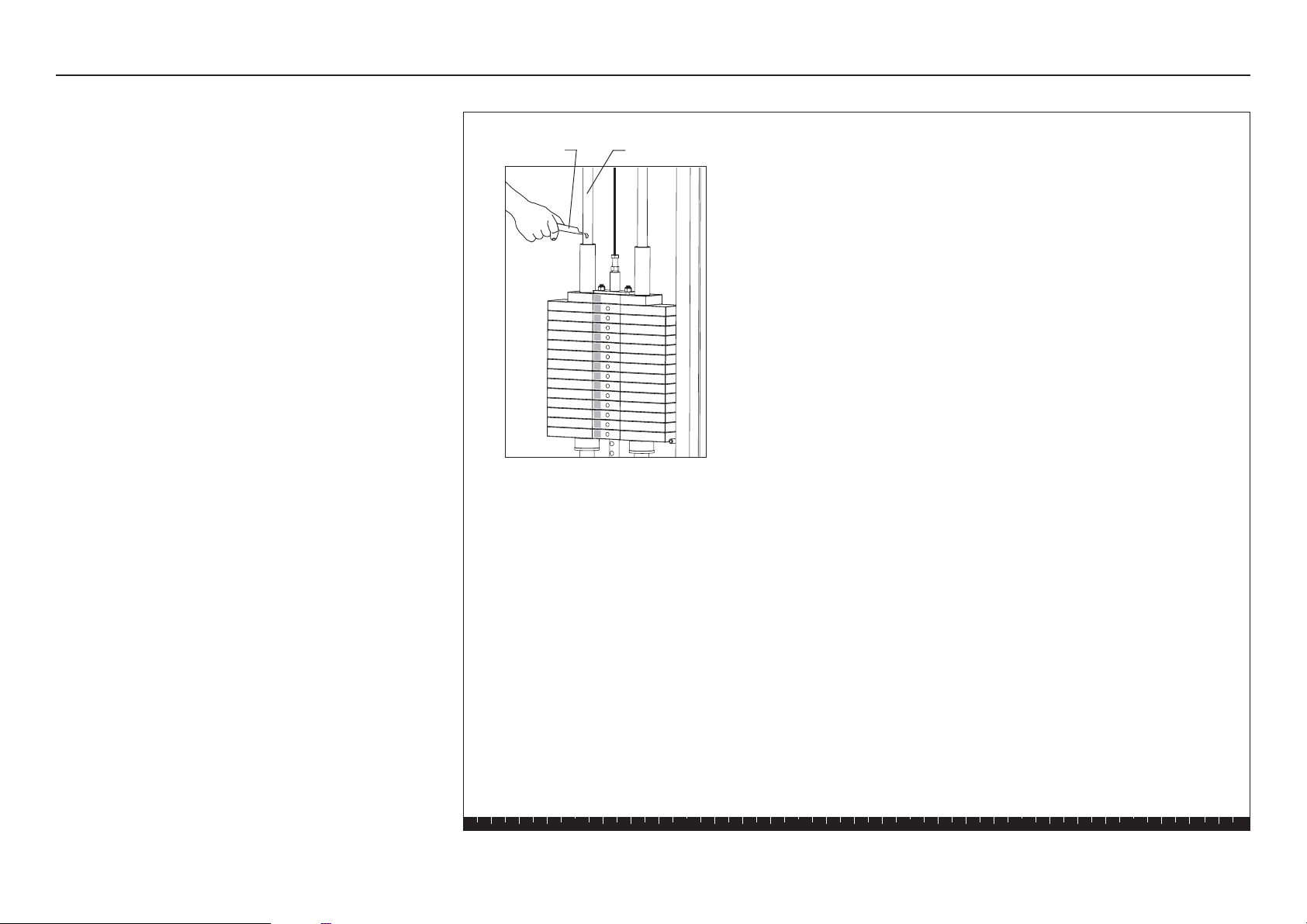
D. Check the Selector Stem alignment by inserting
the Weight Pin into every hole on the Weight Stack.
C
A
D
Threads
Jam Nut
Top Cap
Weight
Jam Nut
B
Thread exposure should remain the
same for both Floating Pulleys.
1
3
2
4
5
6
7
8
9
10
11
12
13
14
15
Top Cap Weight is fully
seated on the top weight.
No gap should appear.
Top Weight
S3.15 Assembly and Maintenance Guide
page 29
1 2 3 4 5 6
3. Maintenance
Guide Rods
Lubricate the Guide Rods every six months.
Inspection
Inspect the unit daily.
Look and listen for loose fasteners, cable tension
issues, unusual noises and any other indications that
the equipment may be in need of service.
You are responsible for the proper maintenance of the
unit as discussed in this manual. For other service
issues, contact Customer Support. Refer to
Obtaining
Service
.
Cable Adjustments and Maintenance, continued
1
3
2
4
5
6
7
8
9
10
11
12
13
14
15
Lubricant Guide Rod

S3.15 Assembly and Maintenance Guide
page 30
1 2 3 4 5 6
Shrouds
CAUTION: Clean the Shrouds with product
specifically labeled as safe for acrylic. Use a clean,
nonabrasive cloth and light pressure to avoid
scratching the acrylic surface.
The acrylic Shrouds on the S3.15 are easily scratched
or damaged through improper cleaning techniques. To
avoid problems, dust the shrouds often with a clean,
lint-free cloth and light pressure. Avoid rubbing dirt or
grit into the surface. If you use glass cleaner or a
similar product, make sure the label states that it is
safe to use on Plexiglas® or acrylic products.
Important: DO NOT use ketones, aromatics, esters,
halogens, window cleaning sprays, alcohol, kitchen
scouring compounds, or solvents (such as acetone,
benzene, gasoline, carbon tetrachloride, or thinners).
Do not use ammonia-based cleaning solutions
because the ammonia destroys the plastic coating.
To remove light scratches on the smooth side only, use
a buffing compound such as, car wax. Lightly buff the
acrylic sheet using a clean buffer until the scratches
disappear.
Cable Adjustments and Maintenance, continued
S3.15 Assembly and Maintenance Guide
page 31
1 2 3 4 5 6
Shroud (frosted side
faces weight stack)
Cutout in
Shroud
A
6 - 1³⁄₄" buttonhead screws
6- tapered spacers
Shroud (frosted side
faces weight stack)
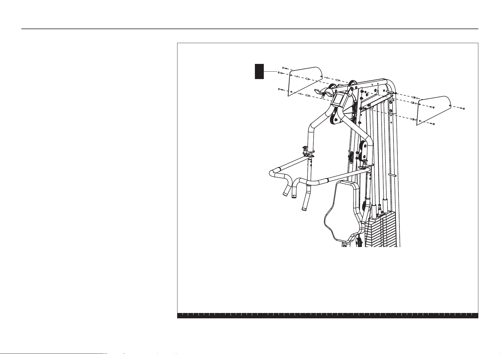
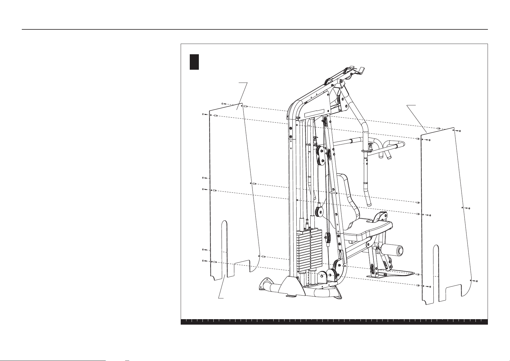
Appendix – Shroud Assembly
Two acrylic Shrouds can be attached to the Main
Frame. Complete the assembly steps for one side of
the unit before moving the other.
The frosted side of the Shroud faces the Weight Stack.
Install the Shrouds so the cutouts allow access to the
Weight Stack Pin.
Important: Handle each Shroud with care. The
shrouds require special handling as they are easily
scratched. For proper care and maintenance, refer to
Adjustments and Maintenance
in this guide.
A. Attach a Shroud to each side of the Main Frame
using
6 - 1¾-inch buttonhead screws
6 - tapered spacers
Note: Start with top fasteners and work toward the
base. Ask your assistant to hold the Shroud in
place while you insert the top spacers and
fasteners. Alternately finger tighten all six fasteners
while adjusting the alignment.
B. Wrench tighten using a 5mm hex key.
CAUTION: Do not over tighten. You can crack or
warp the Shroud if too much pressure is applied to
the fasteners.
Appendix – Shroud Assembly

Effective 01 January 2003
P/N 36287-110
Precor Residential Equipment Limited Warranty
PLEASE READ THESE WARRANTY TERMS AND CONDITIONS CAREFULLY BEFORE USING
YOUR PRECOR INCORPORATED PRODUCT. BY USING THE EQUIPMENT, YOU ARE
CONSENTING TO BE BOUND BY THE FOLLOWING WARRANTY TERMS AND CONDITIONS.
Limited WLimited W
Limited WLimited W
Limited W
arrantyarranty
arrantyarranty
arranty
..
..
.
Precor Incorporated warrants all new Precor products to be free from defects in materials and
manufacture for the warranty period set forth below. The warranty period commences on the
invoice date of original purchase. This warranty applies only against defects discovered within
the warranty period and extends only to the original purchaser of the product. Parts repaired or
replaced under the terms of this warranty will be warranted for the remainder of the original
warranty period only. To make claim under warranty, the buyer must notify Precor or their
authorized Precor dealer within 30 days after the date of discovery of any nonconformity and
make the affected product available for inspection by Precor or its service representative.
Precor’s obligations under this warranty are limited and set forth below.
WW
WW
W
arranty Periods and Coveragearranty Periods and Coverage
arranty Periods and Coveragearranty Periods and Coverage
arranty Periods and Coverage
All residential products and commercial products used in the home are warranted for the
following periods:
• Lifetime frame and welds
• 10 years parts and wear items
• 1 year labor
• Coverage for options and accessories defined below.
Options / AccessoriesOptions / Accessories
Options / AccessoriesOptions / Accessories
Options / Accessories
Many options or accessories have components that are connected internally or mounted inside the
electronic console. The following guidelines determine the warranty for these components. If the
internal components are installed by the factory or by an authorized dealer as part of the original
sale and delivery, they have a warranty that is identical to the warranty of the equipment in which
they are connected or mounted. If the internal components are not installed by the factory or by an
authorized dealer as part of the original sale and delivery, they have a 90-day parts and labor
limited warranty. All components that are not internally connected have 90-day parts only limited
warranty. Satisfactory proof of purchase is required in all cases.
Conditions and RestrictionsConditions and Restrictions
Conditions and RestrictionsConditions and Restrictions
Conditions and Restrictions
This warranty is valid only in accordance with the conditions set forth below:
1. The warranty applies to the Precor product only while:
a. It remains in the possession of the original purchaser and proof of purchase is
demonstrated
b. It has not been subjected to accident, misuse, abuse, improper service, or non-Precor
modifications
c. Claims are made within the warranty period
2. This warranty does not cover damage or equipment failure caused by electrical wiring not in
compliance with electrical codes or Precor owner’s manual specifications, or failure to provide
reasonable and necessary maintenance as outlined in the owner’s manual.
3. Warranty of all Precor products applies to residential use only and is void when products are
used in a nonresidential environment or installed in a country other than where sold.
4. Except in Canada, Precor does not pay labor outside the United States.
5. Warranties outside the United States and Canada may vary. Please contact your local Dealer
for details.
This limited warranty shall not apply to:This limited warranty shall not apply to:
This limited warranty shall not apply to:This limited warranty shall not apply to:
This limited warranty shall not apply to:
1. Software version upgrades
2. Cosmetic items, including, but not limited to the following: grips, seats, and labels.
3. Repairs performed on Precor equipment missing a serial number or with a serial tag that has
been altered or defaced.
4. Service calls to correct installation of the equipment or instruct owners on how to use the
equipment.
5. Pickup, delivery, or freight charges involved with repairs.
6. Any labor costs incurred beyond the applicable labor warranty period.
Disclaimer and ReleaseDisclaimer and Release
Disclaimer and ReleaseDisclaimer and Release
Disclaimer and Release
The warranties provided herein are the exclusive warranties given by Precor and supersede any prior,
contrary or additional representations, whether oral or written. ANY IMPLIED WARRANTIES, INCLUDING THE
WARRANTY OF MERCHANTABILITY OR FITNESS FOR A PARTICULAR PURPOSE THAT APPLY TO ANY PARTS DESCRIBED ABOVE
ARE LIMITED IN DURATION TO THE PERIODS OF EXPRESS WARRANTIES GIVEN ABOVE FOR THOSE SAME PARTS. PRECOR
HEREBY DISCLAIMS AND EXCLUDES THOSE WARRANTIES THEREAFTER.
Some states do not allow limitation on how
long an implied warranty lasts, so the above limitation may not apply to you. PRECOR ALSO HEREBY DISCLAIMS
AND EXCLUDES ALL OTHER OBLIGATIONS OR LIABILITIES, EXPRESS OR IMPLIED, ARISING BY LAW OR OTHERWISE, WITH
RESPECT TO ANY NONCONFORMANCE OR DEFECT IN ANY PRODUCT, INCLUDING BUT NOT LIMITED TO: (A) ANY OBLIGATION,
LIABILITY, RIGHT, CLAIM OR REMEDY IN TORT, WHETHER OR NOT ARISING FROM THE NEGLIGENCE OF PRECOR OR ITS
SUPPLIERS (WHETHER ACTIVE, PASSIVE OR IMPUTED); AND (B) ANY OBLIGATION, LIABILITY, RIGHT, CLAIM, OR REMEDY FOR
LOSS OF OR DAMAGE TO ANY EQUIPMENT.
This disclaimer and release shall apply even if the express warranty set
forth above fails of its essential purpose.
Exclusive RemediesExclusive Remedies
Exclusive RemediesExclusive Remedies
Exclusive Remedies
For any product described above that fails to conform to its warranty, Precor will provide, at their option, one of
the following: (1) repair; (2) replacement; or (3) refund of the purchase price. Precor Limited Warranty service
may be obtained by contacting the authorized dealer from whom you purchased the item. Precor
compensates Servicers for warranty trips within their normal service area to repair equipment at the owner’s
location. You may be charged a trip charge outside the service area. THESE SHALL BE THE SOLE AND EXCLUSIVE
REMEDIES OF THE BUYER FOR ANY BREACH OF WARRANTY.
Exclusion of Consequential and Incidental DamagesExclusion of Consequential and Incidental Damages
Exclusion of Consequential and Incidental DamagesExclusion of Consequential and Incidental Damages
Exclusion of Consequential and Incidental Damages
PRECOR AND/OR ITS SUPPLIERS SHALL HAVE NO OBLIGATION OR LIABILITY, WHETHER ARISING IN CONTRACT
(INCLUDING WARRANTY), TORT (INCLUDING ACTIVE, PASSIVE, OR IMPUTED NEGLIGENCE AND STRICT LIABILITY), OR
OTHERWISE, FOR DAMAGE TO THE EQUIPMENT, PROPERTY DAMAGE, LOSS OF USE, REVENUE OR PROFIT, COST OF
CAPITAL, COST OF SUBSTITUTE EQUIPMENT, ADDITIONAL COST INCURRED BY BUYER (BY WAY OF CORRECTION OR
OTHERWISE) OR ANY OTHER INCIDENTAL, SPECIAL, INDIRECT, OR CONSEQUENTIAL DAMAGES, WHETHER
RESULTING FROM NONDELIVERY OR FROM THE USE, MISUSE OR INABILITY TO USE THE PRODUCT.
This exclusion
applies even if the above warranty fails of its essential purpose and regardless of whether such damages
are sought for breach of warranty, breach of contract, negligence, or strict liability in tort or under any other
legal theory. Some states do not allow the exclusion or limitation of incidental or consequential damages,
so the above limitation might not apply.
This warranty gives you specific legal rights, and you may also have other rights, which vary state
to state.
Complete this porComplete this por
Complete this porComplete this por
Complete this por
tion and keep for your rtion and keep for your r
tion and keep for your rtion and keep for your r
tion and keep for your r
ecorecor
ecorecor
ecor
ds.ds.
ds.ds.
ds.
Purchased From: ____________________________ Example: Dealer or store name.
Phone Number: _____________________________ Example: Dealer or store telephone number.
Product/model: _____________________________ Example: M9.31
Serial number: ______________________________ The serial number is found on the shipping container
page 32

Fold along dotted line and tape closed before mailing.
RET.
To allow us to serve you better, please take a few moments to
complete and return your warranty registration.
YOU MAY ALSO REGISTER ONLINE AT
www.precor.com/warranty
If you have questions or need additional information, contact your
local dealer or call Precor Customer Support at 800-347-4404.
Thank You and Welcome to Precor
Precor Incorporated
20031 142nd Avenue NE
PO Box 7202
Woodinville, WA 98072-4002
PLACE
STAMP
HERE

TELL US ABOUT YOUR NEW PRECOR PRODUCT
Purchased
from:
The serial number is located on the shipping box and on the product.
Product
Serial
Number:
Please indicate the type of product purchased:
❑ Elliptical Fitness CrossTrainer (EFX
®
)
❑ Treadmill
❑ Strength Training System
TELL US ABOUT YOU
Date of
Purchase:
❑ Mr.
❑ Mrs.
❑ Ms.
First Name
Apt./Suite:
TELL US ABOUT YOUR PURCHASE
Please detach and mail in the warranty registration within ten days of purchase.
❑ StretchTrainer
TM
❑ Cycle
❑ Stair Climber
Middle Initial Last Name
Street Address
Zip CodeCity State
Gender: Marital status: Age: Annual household income: What are your fitness goals?
❑ Male ❑ Married ❑ Under 18 ❑ Under $50,000 ❑ Weight loss/management
❑ Female ❑ Divorced ❑ 18-24 ❑ $51,000-75,000 ❑ Muscle tone enhancement
❑ Widowed ❑ 25-34 ❑ $76,000-100,000 ❑ Cardiovascular improvement
❑ Never been married ❑ 35-44 ❑ $101,000-150,000 ❑ Overall health
❑ 45-54 ❑ $151,000+ ❑ Increase energy and flexibility
❑ 55-64 ❑ Stress reduction
❑ 65+ ❑ Rehabilitation
❑ Other
Purchase (check all that apply): How did you FIRST become aware of Precor
❑ First Precor product products (choose only one):
❑ Replaces a Precor product of the same type ❑ A gift
❑ Replaces same type of product – different brand ❑ Friend/relative
❑ Addition to equipment currently owned ❑ Physician
❑ Fitness club
❑ Internet
What factors MOST influenced your decision to ❑ News report or product review
purchase your Precor product (choose up to three): ❑ Magazine advertisement or article
❑ Precor reputation ❑ Print advertisement
❑ Prior use of Precor product(s) ❑ In-store display or demonstration
❑ Design/appearance ❑ Other
❑ Value for the price
❑ Special product features
❑ Rebate or sale price
❑ Quality/durability
❑ Warranty
❑ Physician recommendation
Month
Day
Year
Your Email Address
Area Code
Telephone
Dealer Name
Effective 01 July 2004
P/N 45623-102


Precor is a registered trademark of Precor Incorporated.
Specifications subject to change without notice.
Copyright 2006 Precor Incorporated.
www.precor.com
NOTICE:
Precor is widely recognized for its innovative, award winning designs of exercise equipment. Precor aggressively seeks U.S. and
foreign patents for both the mechanical construction and the visual aspects of its product design. Any party contemplating the use of
Precor’s product designs is hereby forewarned that Precor considers the unauthorized appropriation of its proprietary rights to be a
very serious matter. Precor will vigorously pursue all unauthorized appropriation of its proprietary rights.
Precor Incorporated
20031 142nd Avenue NE
P.O. Box 7202
Woodinville, WA USA 98072-4002
1-800-347-4404
S3.15 Specifications
Length: 72 inches (182 cm)
Height: 83 inches (211 cm)
Width: 51 inches (130 cm)
Shipping weight: 221 lb (100 kg)
S3.15 Literature Kit 49456-101
S3.15 Assembly & Maintenance Manual 49457-101
Registration Card 45623-102
Warranty Statement 36287-110
18 September 2006