Loading ...
Loading ...
Loading ...
INSTALLATION INSTRUCTIONS
19
ENGLISH
18
INSTALLATION INSTRUCTIONS
ENGLISH
2
There are three different wiring configura-
tions.
①
Through the surface of the wall
②
Upper section of Remote Controller
③
Right section of Remote Controller
3
Please make sure to leave no gaps on the
top, bottom, left or right sides between
the remote controller and backplate.
Before assembly with the backplate,
arrange the Cable not to interfere with cir-
cuit parts.
There are two separating holes. Please in-
dividually separate one at a time.
Please be careful not to damage the inside
components when separating.
Wall
Side
Wall
Side
Wall
Side
Wall
Side
<Connecting order>
<Separating order>
4
Please refer to the following directions
when connecting the indoor unit and the
wired remote controller together.
YELLOW RED BLACK
Signal 12V GND
Remote
controller PCB
Indoor unit
side
CAUTION
When installing the wired remote con-
troller do not bury it in the wall. (It can
cause damage in the temperature sensor.)
Do not exceed 164ft(50m) for cable
length.
(It can cause communication error.)
Specification of LG supplied extension
cable : AWG 24, 3 conductor or above.
(Model : PZCWRC1)
!
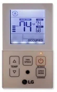
Since the room temperature sensor is in the
remote controller, the remote controller box
should be installed in a place away from direct
sunlight, high humidity and direct supply of
cold air to maintain proper space temperature.
Install the remote controller about 5ft(1.5m)
above the floor in an area with good air circu-
lation at an average temperature.
Do not install the remote controller where it
can be affected by:
- Drafts, or dead spots behind doors and in
corners.
- Hot or cold air from ducts.
- Radiant heat from sun or appliances.
- Concealed pipes and chimneys.
- Uncontrolled areas such as an outside wall
behind the remote controller.
- This remote controller is equipped with LCD
display. For proper display of the remote con-
troller LCD's, the remote controller should be
installed properly as shown in Fig.1. (The
standard height is 4~5 ft (1.2~1.5 m) from
floor level.)
5feet
(1.5meters)
(Fig. 1)
Direct
Sun ray contact area
no
no
no
yes
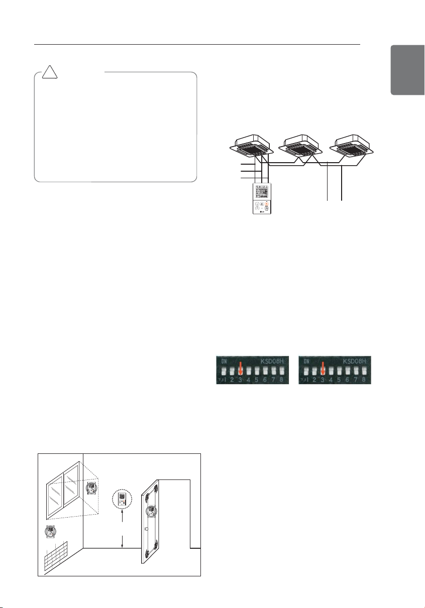
When installing more than 2 units of air condi-
tioner to one Thermostat, please connect as
pictured to the right.
- Set one indoor unit to master and the re-
maining to slave.
GND
GND
12V
Signal wire
Signal wire
When controlling multiple indoor units with
one Thermostat, you must change the mas-
ter/slave setting from the indoor unit.
- Once DIP S/W is set, recycle power. When
recycling power, please remain in OFF posi-
tion for at least 1 minute for new settings to
take effect.
- For ceiling type cassette and duct product
group, change the switch setting of the in-
door PCB.
#3 switch OFF:
Master (Factory
default setting)
#3 switch ON: Slave
- For wall-mount type and stand type product,
change the master/slave setting with the
wireless.
Thermostat. (Refer to wireless Thermostat
manual for additional information)
When controlling the group, some advanced
functions (excluding basic operation setting,
fan level Low, med, high, Thermostat lock
setting and time setting) may be limited.
Installation
1
Please fasten the back plate securely to
the wall using the provided screws.
Please ensure to not bend the back plate
as this could cause issues with installation.
INSTALLATION INSTRUCTIONS
Remote controller installation
1,MFL62862020, 2018. 1. 3. 1:01 Page 18
Loading ...
Loading ...
Loading ...