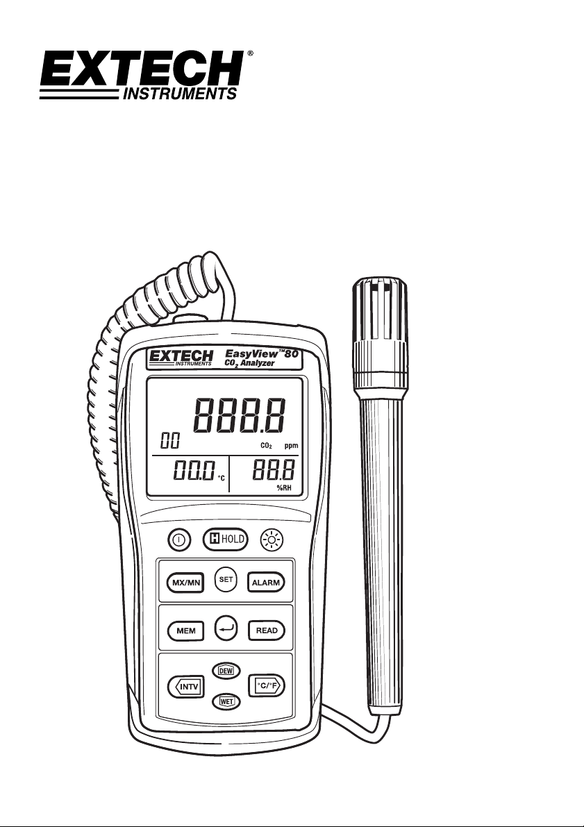
User Guide
Indoor Air Quality Meter/Datalogger
Model EA80
EA80-EU-EN v3.2 08/13
2
Ø
2.5
Introduction
Congratulations on your purchase of the Extech EA80 Indoor Air Quality Meter. This meter measures
Carbon Dioxide (CO
2
, ppm) levels, ambient Temperature and Relative Humidity (%RH). 20,000
readings can be logged by the meter and later transferred to a PC.
This meter is shipped fully tested
and calibrated and, with proper use, will provide years of reliable service.
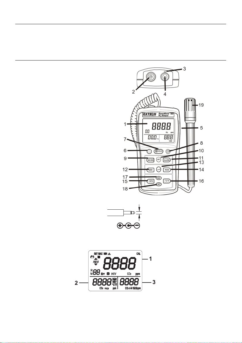
Description
1. Display
2. Gas exhaust
3. Gas inlet port
4. PC Interface jack
5. AC adapter socket (9V, 300mA)
6. Power Button
7. Data Hold Button
8. Backlight Button
9. MX/MN Button
10. SET Button
11. ALARM button
12. MEM (memory) button
13. (Enter) button
14. READ button
15. TIME button
16. °C/°F button
17. DEW button
18. WET button
19. Temperature / Humidity sensor probe
Three Tier LCD Display
AC Adaptor Phono Plug
EA80-EU-EN v3.2 08/13
3
Preparation for Use
Power Supply
The meter is powered by six (6) 1.5V ‘AAA’ alkaline batteries or by an AC adapter.
Installing the Batteries
Insert six (6) AAA batteries as indicated by the diagram located on the inside of the battery
compartment.
When the battery voltage drops below the operating voltage, the “
+
” indicator will be
displayed indicating that the batteries need to be changed.
AC Adapter
The AC adapter allows the meter to be powered from a common AC wall outlet. When using the
AC adapter, the batteries (if installed) will be bypassed. The AC adapter is not a battery charger.
Gas Inlet
Always ensure that the meter’s gas inlet port and gas exhaust are not blocked.
Operation
Note: Exhaled CO
2
will affect the accuracy of the reading; do not hold meter near the
face.
Taking Measurements
The sensor for Temperature, Humidity, Dew Point, and Wet Bulb measurements is located in the
remote probe. Hold the probe in the air in the area to be tested. DO NOT immerse in liquid. The
sensor for CO2 measurements is located at the top of the meter.
Selecting temperature units of measure (C/F)
Press the °C/°F button momentarily to toggle the temperature units.
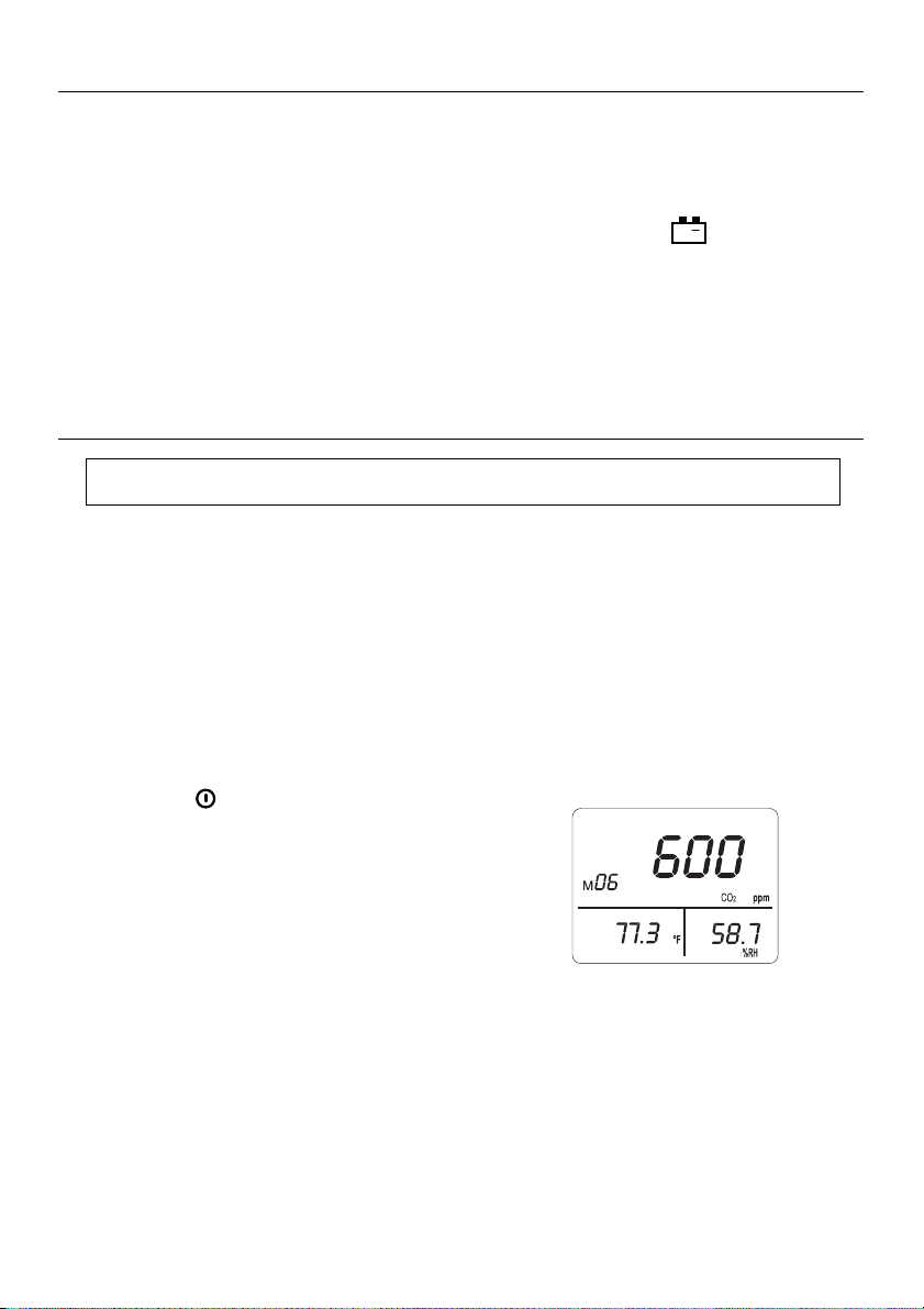
CO2 Measurement
1. Press
button to turn on the meter,
2. The sensor requires a 30 second warm-up before
displaying the CO2 measurement.
3. The meter sensor requires approximately10 minutes
to stabilize in still air before the readings can be
considered accurate. Moving the meter may
decrease this stabilization time.
4. The primary display indicates the CO2 reading. The
secondary display indicates temperature. The third display indicates %RH.

EA80-EU-EN v3.2 08/13
4
Humidity Measurement
1. Press the “
” button to power the meter ON.
2. The display will indicate the humidity reading (% RH) directly on the third display.
3. Hold the probe in the air in the area to be tested. Do NOT immerse in liquid.
4. Allow adequate time for readings to stabilize.
5. Read the measurements on the LCD.
Temperature Measurement
1. Press the “ ” button to power the meter ON.
2. Press the °C/°F button momentarily to toggle the temperature units.
3. The display will show the Temperature reading directly on the second display.
4. Allow adequate time for readings to stabilize.
5. Read the measurements on the LCD.
Dew Point Temperature Measurement
1. Press the “
” button to power the meter ON.
2. Press the “DEW” button
3. The display will show the Dew Point Reading on the second display.
4. Allow adequate time for the readings to stabilize
5. Read the measurements on the LCD.
6. Press the “DEW” button again to exit the dew point temperature reading.
Wet Bulb Temperature Measurement
1. Press the “
” button to power the meter ON.
2. Press the “WET” button
3. The display will show the Wet Bulb Reading on the second display.
4. Allow adequate time for the readings to stabilize
5. Read the measurements on the LCD.
6. Press the “WET” button again to exit the display.
EA80-EU-EN v3.2 08/13
5
MAX
CO
2
ppm
d-h
m:s
8
MIN
CO
2
ppm
d-h
m:s
CO
2
ppm
d-h
m:s
CO
2
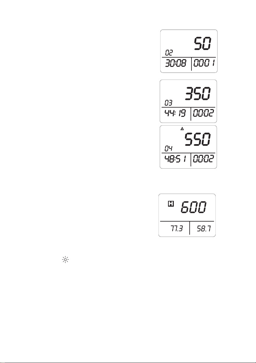
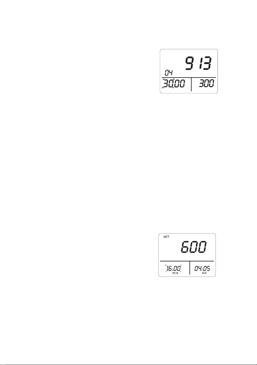
Maximum and Minimum Recording Measurement
1. Press “MX/MN” button to enter the maximum /
minimum recording mode, the “MAX” icon appears on
the display. The maximum CO2 reading will be
displayed and will be updated only when a higher
reading occurs.
2. Press “TIME” button to enter time display mode.
Displays 2 and 3 will indicate the time the maximum
reading occurred.
3. Press “MX/MN” button again. The “MIN” icon will
appear with the minimum value and its stamp time.
4. Press “MX/MN” button again. The “△” icon will
appear with the current value and current time.
5. Press “MX/MN” button again cycle through the
recorded MAX, MIN and current readings.
6. Press “” button to exit this mode.
7. Press “TIME” button exit the time display mode.
Data Hold
1. Press the H button momentarily to freeze the
displayed reading. The 'H' icon will appear on the
upper left-hand side of the display.
2. Press the H button again to return to normal
operation (the 'H' hold icon will disappear).
Backlight
1. Press the button to turn the backlight on or off.
2. The backlight will turn off automatically after 30 seconds.
SET
MAX
MIN
ALM
R
M
Err
INTV
Err
CO
2
ppm
ppm
%RH
d-h
CO
2
DEW
WET
°C°F
ppm
CO
2
m:s
8888
8888
8888
88
CAL
EA80-EU-EN v3.2 08/13
6
SET
ALM
CO
2
ppm
ppm
CO
2
ppm
CO
2
CO
2
Alarm Operation
Setting the Alarm Limit Values
1. Press “ALARM” button to turn on the alarm function, the “ALM” icon, and current value are
displayed.
2. Press “SET” button to enter High/Low limit value
setting mode, the “SET” icon is displayed and
hundred and thousand digits of the high limit value
will flash.
3. Press “” or “” button to set desired value.
4. Press “” button to move the cursor to set the tens
and ones digits.
5. Press “” or “” button to enter the desired value.
6. Press “” button to move the cursor to the hundred and thousand digits of the low limit
value.
7. Press “” or “” button to set desired value.
8. Press “” button to move the cursor to move the cursor to set the tens and ones of the low
limit value.
9. Press “” or “” button to set desired value.
10. To change any setting, press “” or “” button to move the cursor to desired high or low
limit value position.
11. Press “” button to store these setting and exit this mode.
Turning Alarm On / Off
1. Press “ALARM” button to turn on the alarm function, “ALM” is displayed.
2. When the CO
2
value is below the low limit value, the meter displays “” mark and beeps.
3. When the CO
2
value exceeds the high limit value, the meter displays “” and beeps.
4. To exit the ALARM function, press “ALARM” button again.
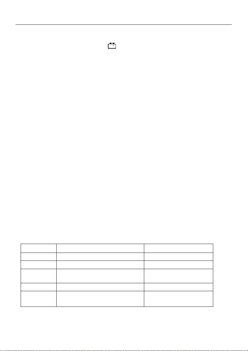
Setting the Real Time Clock
1. Press “SET” button to enter the real-time clock
setting mode, “SET” is displayed and the minutes
are flashing.
2. Press “” or “” button to set the minutes.
3. Press “” button to move the cursor to seconds.
4. Press “” or “” button to set the seconds.
5. Press “” button to move the cursor the days.
6. Press “” or “” button to set the day of the real time date. (Please note that this is not a
calendar. Days are elapsed days up to 99 total)
7. Press “” button to move the cursor to the hours. (Please note that this is a 24 hour clock)
8. Press “” or “” button to set the hours.
9. To change any setting, press “” or “” button to move the cursor to desired position.
10. Press “” button to store the settings and exit this mode.
SET
MAX
MIN
ALM
R
M
Err
INTV
Err
CO
2
ppm
ppm
%RH
d-h
CO
2
DEW
WET
°C°F
ppm
CO
2
m:s
8888
8888
8888
88
CAL

EA80-EU-EN v3.2 08/13
7
Manual Datalogging
Storing readings
Press the "MEM" button. The LCD will display "M" and the
memory address number. The total memory size is 99
readings.
Viewing readings
Press the "READ" button to enter READ mode. The LCD will
display "R" and the memory address number.
Press " " or " " to scroll through the stored readings.
Press " " enter to exit this mode.
Deleting stored data
Press the “SET” button three times. The LCD will display “CLr” and the meter will enter the Clear
Memory mode.
Press “” to clear the all manually stored readings.
To abort, press the “SET” button twice and then press the “” button to exit the Clear Memory
mode.
Auto Datalogging
Setting interval time
Press “SET” two times. The “INTV” mark will appear and the meter will enter the Interval Time
setting mode.
Use the “” or “” button to select the desired interval time from 1 to 255 seconds.
Press the “” button to store the value and to exit the mode.
Auto Datalogging mode
Press and hold “MEM” for two seconds (3 beeps), the LCD will display the “ ” icon and the
memory location.
The “M” will flash each time a recording is made.
The maximum memory capacity is 20,000 recordings that can be divided into 99 sets.
Press the “” button to exit this mode and to stop recording.
Deleting Logged Data
Press “SET” four times, the “CLr” and “ ” mark will be displayed.
Press the “” button to clear the automatically stored data and to exit this mode.
To abort, press the “SET” button again then press the “” button to exit.
SET
MAX
MIN
ALM
R
M
Err
INTV
Err
CO
2
ppm
ppm
%RH
d-h
CO
2
DEW
WET
°C°F
ppm
CO
2
m:s
8888
8888
8888
88
CAL

EA80-EU-EN v3.2 08/13
8
Calibration
CO2 Calibration
1. Press “
” to turn the meter on.
2. Place the probe in a known CO
2 reference for 10 minutes.
3. Press the “SET” button 5 times until “C-01” is displayed in the second display.
4. Press “►” or “◄” to select digits to adjust (flashing).
5. Press “▼” or “▲”to adjust the display to the reference value.
6. Press “” to store the value and exit the calibration mode.
Humidity Calibration
1. Press “
” to turn the meter on.
2. Place the probe in a known humidity reference for 60 minutes.
3. Press the “SET” button 6 times until “SET” and “CAL” are displayed on the LCD.
4. Press “▼” or “▲” to adjust the display to the reference value.
5. Press “” to store the value and exit the calibration mode.
Temperature Calibration
1. Press “
” to turn the meter on.
2. Place the probe in a known temperature reference for 60 minutes.
3. Press the “SET” button 7 times until “SET” and “CAL” are displayed on the LCD.
4. Press “▼” or “▲” to adjust the display to the reference value.
5. Press “” to store the value and exit the calibration mode.
EA80-EU-EN v3.2 08/13
9
Specifications
Display Three Tier LCD
Display Rate One reading per second
Low Battery Indication The “
+
” icon is displayed when the battery voltage drops
below the operating voltage
Power Supply Six (6) AAA-size alkaline batteries or AC adapter
Battery Life Approx. 8 hours using alkaline batteries (with backlight and Alarm
functions OFF)
Manual Data Memory Capacity 99 sets
Auto Datalogging Capacity 20,000 sets (maximum 99 blocks)
Operating Temperature Range 5°C to 50°C (41°F to 122°F)
Storage Temperature Range -10°C to 60°C (-14°F to 140°F)
Operating Humidity Range 10%RH to 90%RH, non-condensing
Storage Humidity Range 10%RH to 90%RH, non-condensing
Dimensions 158 (L) x 72(W) x 35(H) mm (6.22” x 2.83” x 1.38”)
Weight 255g (0.56 lbs) approx. (including batteries)
Accessories Instruction Manual, Batteries, AC Adaptor, Software CD ROM,
and PC Interface Cable
CO2 Specifications
Sensing Range 0 to 6000ppm
Sensing Resolution 1ppm
Accuracy 3% of reading or 50ppm, whichever is greater
@ 101.4 kPa (29.92 inHg) and @ 25°C (77°F)
Sensing Method Dual wavelength detector with non- dispersive infrared (NDIR)
sensor
Gas Sampling Mode Diffusion type
Warm up time 10 seconds
Response time < 10 minutes in still air
Temperature Coefficient Add 0.36% of reading per °C (0.2% of reading per °F) when
deviating from calibration temperature
Temperature & Humidity Specifications
Relative Humidity Temperature
Range 10% ~ 95% RH -20°C ~ +60°C (-4°C ~ +140°F)
Resolution 0.1% RH 0.1°C (0.1°F)
Accuracy
3%RH @ 25°C(77°F), 30~95%RH)
5%RH @ at 25°C(77°F), 10~30%RH)
0.5°C (0.9°F)
Sensor type Precision capacitance sensor Thermistor
Response time
45%RH95%RH≦1min
95%RH45%RH≦3min
10°C / 2sec
EA80-EU-EN v3.2 08/13
10
Maintenance
Cleaning
Periodically wipe the case with a dry cloth or a damp cloth with mild detergent.
Do not use abrasives or solvents to clean this instrument.
Battery Replacement
When the “ ” symbol appears on the LCD, the six 1.5V ‘AAA’ must be replaced.
1. Turn the meter off
2. Remove the meter’s rubber protective jacket
3. Remove the flat-head screw at the rear of the meter
4. Remove the meter’s battery cover
5. Replace the batteries observing polarity
6. Affix the battery cover, secure the rear screw, and re-attach the meter’s rubber protective
jacket
You, as the end user, are legally bound (Battery ordinance) to return all used batteries
and accumulators; disposal in the household garbage is prohibited!
Bring used batteries / accumulators to the collection points in your community or
wherever batteries / accumulators are sold!
PC Interface, Software Installation and Operation
Software operational instructions are located on the software disc. Install the software by inserting
the disc in the PC CD-ROM drive and following the on-screen prompts. Open the program and read
the HELP utility for software instructions.
Copyright©2013FLIRSystems,Inc.
Allrightsreservedincludingtherightofreproductioninwholeorinpartinanyform
ISO‐9001Certified
www.extech.com