Loading ...
Loading ...
Loading ...
En-3
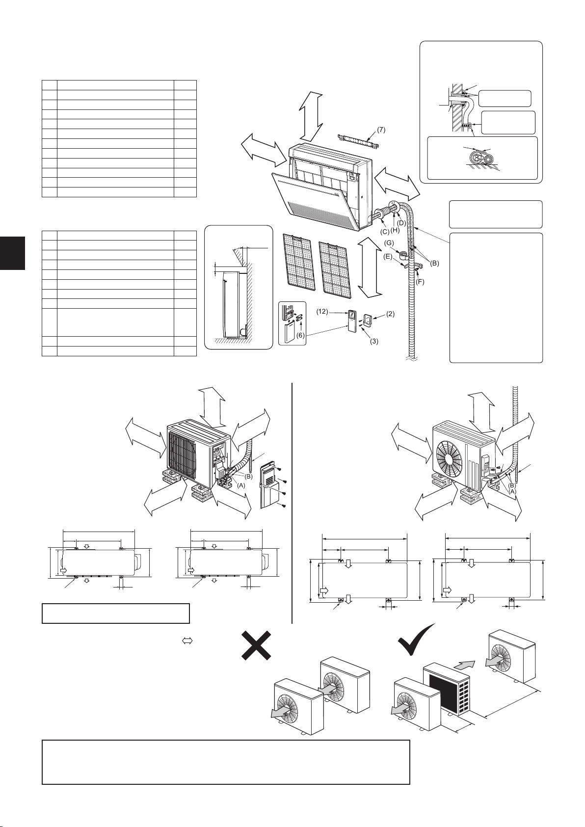
1-4.INSTALLATIONDIAGRAM
ACCESSORIES
Check the following parts before installation.
<Indoor unit>
(1) Drain hose *1 1
(2) Remote controller holder 1
(3) Screws for (2) 3.5 × 16 mm (Black) 2
(4) Pipe cover 1
(5) Band 2
(6) Battery (AAA) for (12) 2
(7) Indoor unit mounting bracket 1
(8)
Fixing screws for (7) 4 × 25 mm
5
(9) Woodscrewforindoorunitxation 4
(10) Washer of (9) 4
(11)
Felt tape (For left or left-rear piping)
1
(12) Wireless remote controller 1
Note:
*1 The Drain hose is connected to the unit.
FIELD-SUPPLIED PARTS
(A) Indoor/outdoor unit connecting wire *2 1
(B) Extension pipe 1
(C) Wall hole sleeve 1
(D) Wall hole cover 1
(E) Pipexingband 2 to 5
(F) Fixing screw for (E) 4 × 20 mm 2 to 5
(G) Piping tape 1
(H) Putty 1
(J)
Drain hose
(or soft PVC hose, 19/32 in. (15 mm) in-
ner diameter or hard PVC pipe VP16)
1
(K) Refrigeration oil 1
(L) Power supply cord *2 1
Units should be installed by licensed contractor
according to local code requirements.
After the leak test, apply
insulating material tightly so
that there is no gap.
When the piping is to be at-
tached to a wall comprised of
tin plate or metal netting, use
chemically treated wooden
piece 25/32 in. (20 mm) or
thicker between the wall and
the piping, or wrap insulation
vinyl tape 7 to 8 turns around
the piping.
To use existing piping, perform
COOL operation for 30 min-
utes and pump down before
removing the old air condi-
tioner.Remake are accord-
ing to the dimension for new
refrigerant.
(L)
(J)
4 in. (100 mm)
or more
14 in. (350 mm)
or more
8 in. (200 mm) *4
or more
4 in. (100 mm)
or more
Unit: inch Unit: mm
31-1/2
19-11/16
Air inlet
Air outlet
13-9/16
11-1/4
2-3/8
×
13/16
slot
12~12-3/4
1-9/16
800
500
Air inlet
Air outlet
2-10
×
21 slot
344.5
285
150
40
304~325
5-15/16
<KJ09/12> <KJ15/18>
(J)
(L)
Unit: inch Unit: mm
4 in. (100 mm)
or more
4 in. (100 mm)
or more
14 in. (350 mm)
or more
20 in. (500 mm) *6
or more
Drain piping for outdoor unit
Install the unit horizontally.
Do not use drain socket in cold regions. Drain may freeze and make the fan stop.
The outdoor unit produces condensate during the heating operation. Select the installation place to ensure to prevent
the outdoor unit and/or the grounds from being wet by drain water or damaged by frozen drain water.
33-1/16
13-3/4~14-5/8
19-11/16
Air inlet
Air inlet
Air inlet
Air inlet
Air inlet
6-7/8
15-3/8
13
Air outlet
2-3/8 × 13/16 slot
1-9/16 40
840
175 500
Air inlet
390
330
349~371
Air outlet
2-10 × 21 slot
clear *3
*3 4 in. (100 mm) or more when front
and sides of unit are clear
*4 When any 2 sides of left, right
and rear of unit are clear
clear *5
*5 20 in. (500 mm) or more when front
and sides of unit are clear
*6 When any 2 sides of left, right
and rear of unit are clear
Obstacles above
It’s possible to
install an obstacle
to the following
area.
Use the wall hole sleeve (C) to prevent
indoor/outdoor connecting wire (A) from
contacting metal parts in the wall and
to protect the wiring from rodents.
Indoor
unit
Wall hole
sleeve (C)
Cut off the
extra length.
Pipe attachment
strap (E)
Wall hole cover (D)
Seal the wall hole
gap with putty (H).
Attach the pipe
to wall with pipe at-
tachment strap (E).
Attachment screw (F)
Note:
*2 Place indoor/outdoor unit connecting wire (A) and power supply cord (L) at least 3 ft. (1 m) away from the TV antenna wire.
Note:
• The dimensions indicated in the arrows (
) above
show the required space to guarantee performance of
the air conditioner. Install the outdoor unit where the
maximum possible space can be provided, considering
later relocation, services, or repairs.
• Thecooling/heatingperformanceandtheefciencyof
power usage may fall about 10% at the place where short
cycle is likely occur due to poor ventilation. Installing the
air outlet guide (optional) can improve performances.
• If air from the outlet blows against the wall, it may cause
stains on the wall.
Do not take in the outlet air
discharged by other units directly.
15-3/4 in. or more
(400 mm or more)
39-3/8 in. or more
(1000 mm or more)
6 in. (150 mm) or
belowfromtheoor
4 in. (100 mm)
or more
No obstruction
4 in. (100 mm)
or more
1-37/64 in.
(40 mm) or
less
30° or less
1-49/64 in. (45 mm) or more
RG79Y918H02_en.indd 3 2019/05/10 8:54:03
Loading ...
Loading ...
Loading ...