Loading ...
Loading ...
Loading ...
English 25
Installation
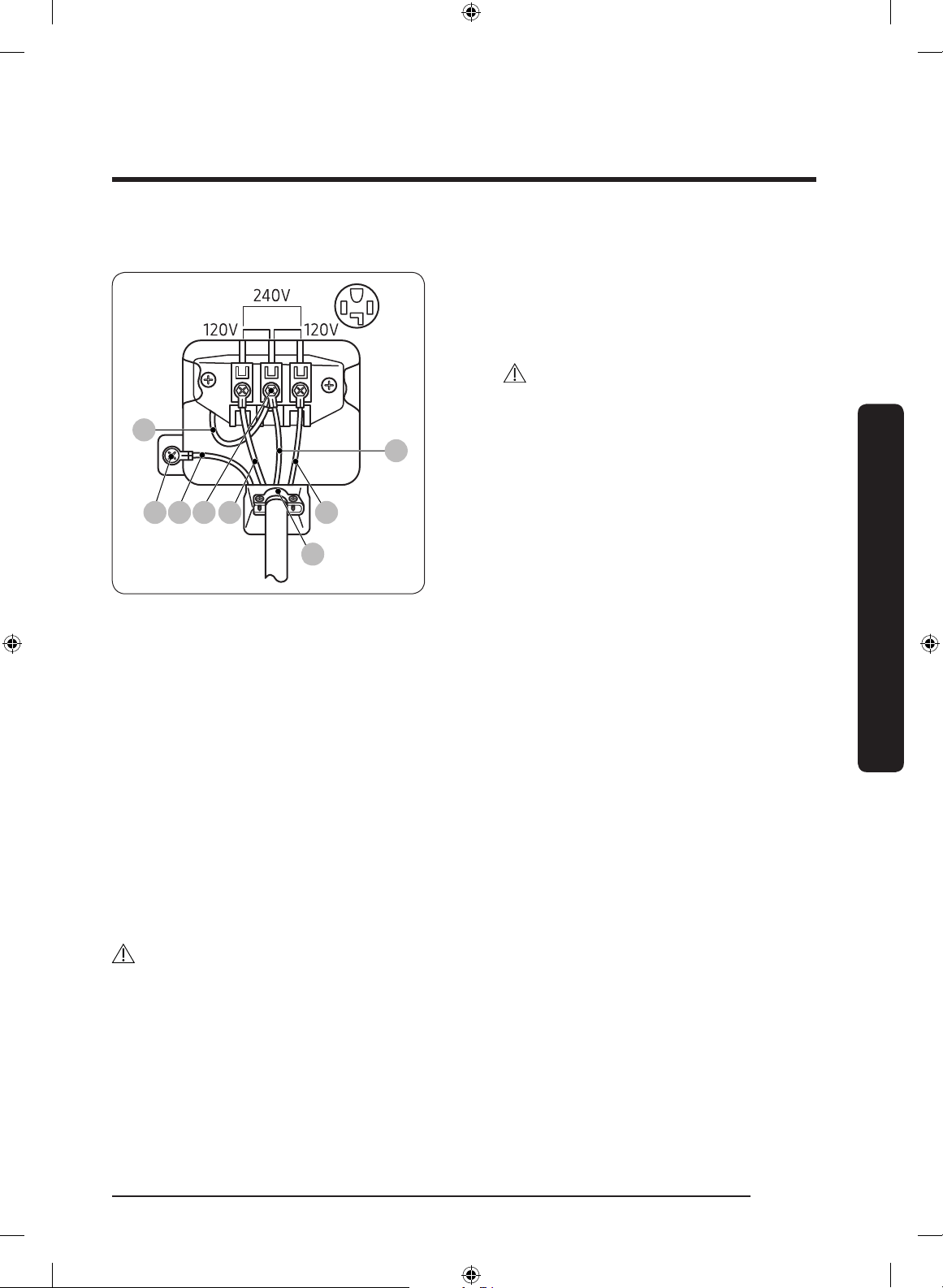
4-wire system
F
A B C L2 L1
D
E
A. External ground connector
B. Neutral grounding wire (white)
C. Center silver-colored terminal block
screw
D. Neutral wire (white or center wire)
E. ¾” (1.9 cm) UL-listed strain relief
F. Neutral wire (white or center wire)
1. Remove the external ground
connector’s screw and connect the
ground wire (green or unwrapped) of
the power cable to the screw.
CAUTION
- To connect the ground wire to the
neutral position without through
contact A (cabinet ground), contact
a technician. This is not user
serviceable.
- Ring-type terminals are
recommended. If using strap
terminals, make sure they are
tightened.
2. Loosen or remove the screws from the
center terminal block.
3. Connect the neutral wire (white or
center wire) and ground wire (white) to
the center screw of the terminal block.
Tighten the screw.
4. Connect the other wires to the outer
terminal block screws. Tighten the
screws.
5. Tighten the strain relief screws.
6. Insert the tab of the terminal block
cover into the rear slot of the dryer.
Secure the cover with a hold-down
screw.
CAUTION
Before Installing the Dryer, conrm 240 V is present between L1 and L2 at the power
receptacle. If the Voltage is low, it may not dry properly. Review the “Electrical
requirements” section on page 18 if needed.
Untitled-13 25 2020-07-14 3:30:06
Loading ...
Loading ...
Loading ...