Loading ...
Loading ...
Loading ...
EN
3
Signal input
• Line-level inputs: If your source unit offers preamp outputs,
connect the front outputs to inputs 1 and 2 on the amplifier, the
rear outputs to inputs 3 and 4, and the subwoofer outputs to
inputs 5 and 6 using RCA patch cables.
Note: when using low-level signals and remote turn-on lead, set
the “Turn-on Mode” switch to “REM” and the “Input Level” switch to
“LO”.
1
2
3
4
5
6
REM DC AUDIO
TURN-ON
MODE
INPUT
LEVEL
LO HI HI2
• High-level inputs: If your audio system’s source unit does
not have line-level outputs, use the supplied high-level input
adapters to connect to the speaker output wires of your source
unit to the RCA inputs of the amplifier. The 12-volt DC offset
feature will turn the amplifier on when it senses signal.
NOTE: You can connect the wires from as many as six of your
vehicle’s speakers to the amplifier. For example, these can include
front left and right tweeters to inputs 1 and 2, front left and right
woofers to inputs 3 and 4, and rear left and right full-range speakers
to inputs 5 and 6. The signals from each of these speakers can be
summed to create a full-range output, if necessary, and assigned to
any of the amplifier output wires. See “Setting the Sound” for more
details.
NOTE: When using high-level signals, set the “Turn-on Mode” switch
to “DC” (to turn on when it receives battery power) or “AUDIO” (to
turn on when it senses signal from your source unit), and the “Input
Level” switch to “HI”. If no sound plays, change the “Input Level”
switch to “HI2”.
1
2
3
4
5
6
Loosen
Screws
Insert
Wires
Tighten
Screws
REM DC AUDIO
TURN-ON
MODE
REM DC AUDIO
TURN-ON
MODE
INPUT
LEVEL
LO HI HI2
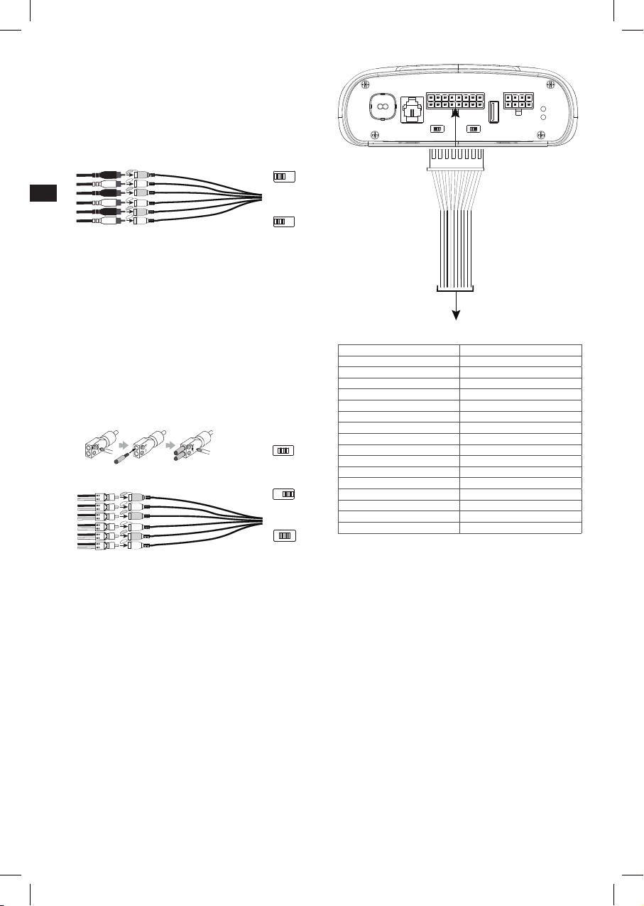
Speaker Output Connections
Connect your speakers to the wires of the speaker output wiring
harness, observing proper polarity: connect each positive (+) lead
to the appropriate positive (+) speaker terminal, and negative (-)
lead to the appropriate negative (-) speaker terminal. Then plug the
speaker output wiring harness into the DSP Amplifier.
NOTE: You can connect up to 8 speakers to the JBL DSP Amplifier,
then specify the frequencies the amplifiers sends to each one with the
JBL tuning software. See “Setting the Sound” for details.
NOTE: If you decide you need more power in your system, you can
use two or more of the speaker output wires to connect one or more
additional amplifiers. Connect the desired number of speaker output
wires to the high-level inputs of the new amplifier(s). IMPORTANT: make
sure to adjust the output levels of the channels you are connecting to
the extra amplifier(s) to ensure that you do not overdrive the external
amplifier(s) and reduce noise, if present.
IMPORTANT: None of the speaker output channels can be bridged.
REMOTE
INPUT
LEVEL
LO HI HI2 REM DC AUDIO
TURN-ON
MODE
PC
SPEAKER OUTPUT CHANNELS POWER
REM OUT GND
GND
GND
12V
12V
12V
REM IN
PRT
PWR
AUDIO
INPUT
8+1+ 2+ 3+ 4+ 5+ 6+ 7+
8-1- 2- 3-
4- 5-
6- 7-
To speakers
Wire color Channel designation
White Channel 1 +
White/Black Channel 1 –
Gray Channel 2 +
Gray/Black Channel 2 –
Green Channel 3 +
Green/Black Channel 3 –
Purple Channel 4 +
Purple/Black Channel 4 –
Orange Channel 5 +
Orange/Black Channel 5 –
Blue Channel 6 +
Blue/Black Channel 6 –
Red Channel 7 +
Red/Black Channel 7 –
Yellow Channel 8 +
Yellow/Black Channel 8 –
Connecting the remote bass control
Plug the remote bass controller into the appropriate input on
the control panel of the DSP Amplifier. Mount the remote in a
convenient location, such as under the dash, using sheet metal
screws.
NOTE: The remote bass control is capable of controlling the subwoofer
output level from channel 7 or 8 when assigned as a “sub” channel.
This will allow adjustment of subwoofer level from -30dB to +6db in the
tuning software. It is not a bass boost control. We expect that you will
use the remote bass control from an external subwoofer amplifier should
you want to control bass boost.
OR
Loading ...
Loading ...
Loading ...