Loading ...
Loading ...
Loading ...
9
NEW CONSTRUCTION INSTALLATION
1. Run speaker wire from the amplifier and audio
component location to desired speaker locations.
See page 4 for wire gauge chart.
2. We recommend that you reinforce the top and
bottom joint locations with a face-block-oriented
2x4 or 3/4” (19mm) plywood. See the construction
diagram on pages 6–7 and the chart below for
opening height dimensions. Product dimensional
drawings are available on www.sonance.com.
Ensure there is a flush, level surface around the
full perimeter of the speaker location before
proceeding.
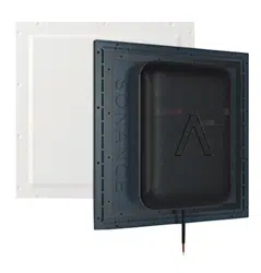
3. Place space saver, preconstruction zip ring
bracket, or both in desired speaker location. See
page 4 for when to use space savers and zip rings.
Space savers are recommended for every new
construction project. Zip rings are recommended as
a time-saver on very large projects with dozens of
invisible speakers.
OPENING HEIGHT FOR TOP/BOTTOM
JOINT SUPPORTS
X (opening height)
IS6
15”
381mm
IS8/IS10W
23”
585mm
IS10
27.5”
700mm
4. Use the wire management built into the space
saver/zip ring to keep your cables in place. With the
aid of a level, screw the space saver/zip ring to the
studs, making sure it’s centered horizontally.
5. Complete drywall installation to the rest of the room
including the surface around the speakers.
NOTE: Sonance recommends using the included
stainless steel screws around the speaker locations.
This is to avoid interfering with the Sonance
DISC system depth gauge operation after install.
Though this is not required, it will improve the
accuracy of finish thickness measurements later on.
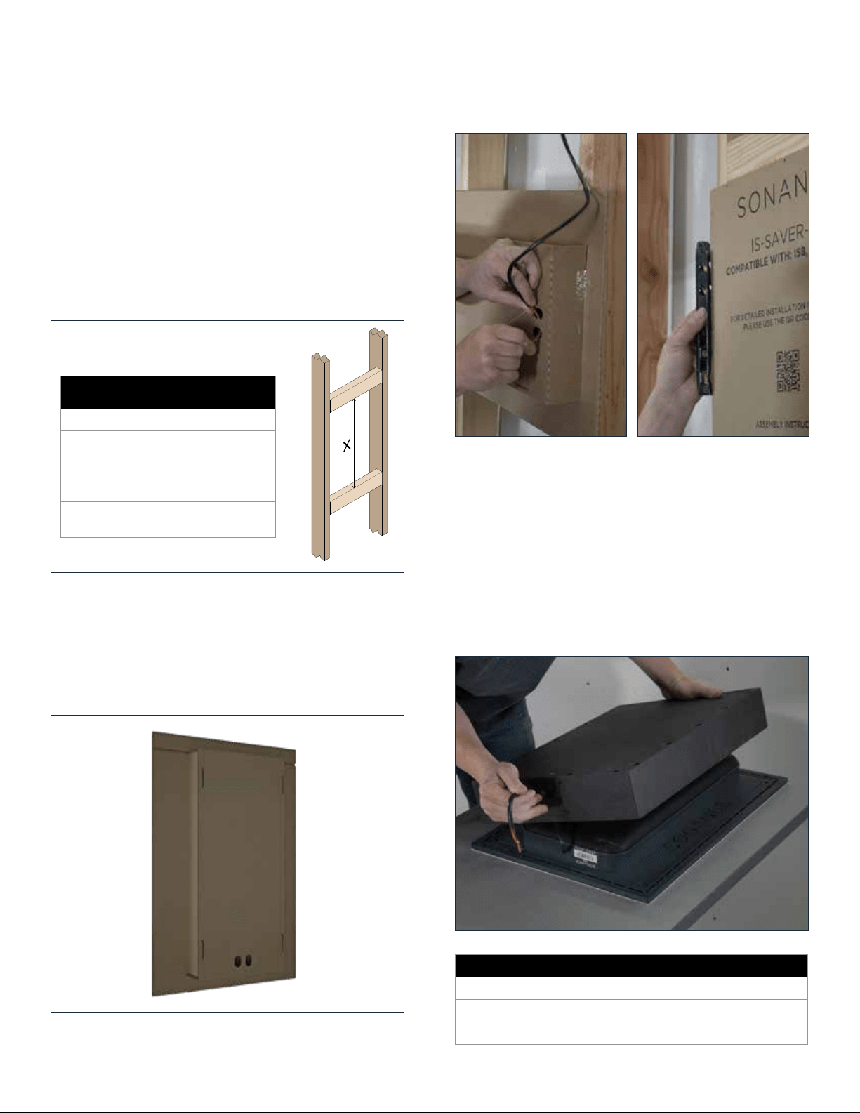
6. OPTIONAL: Secure the sound-isolating enclosure
(sold separately to the back of your IS speaker.
SOUND-ISOLATING ENCLOSURE PART NUMBERS
IS-ENCL-S IS6 93488 Each
IS-ENCL-M IS8/IS10W 93489 Each
IS-ENCL-L IS10 93490 Each
Loading ...
Loading ...
Loading ...