Loading ...
Loading ...
Loading ...
46
10-3. TROUBLESHOOTING CHECK TABLE
No. Symptom LED indication
Abnormal point/
Condition
Condition Remedy
1
Outdoor unit
does not op-
erate.
1-time blink every
2.5 seconds
Outdoor power sys-
tem
Overcurrent protection cut-out operates 3 consecutive times
within 1 minute after the compressor gets started.
•
Reconnect connector of compres-
sor.
•
Refer to 10-5.
"How to check
inverter/compressor".
•
Check stop valve.
2
Outdoor thermistors Discharge temperature thermistor, n temperature thermistor,
defrost thermistor, P.C. board temperature thermistor, outdoor
heat exchanger temperature thermistor or ambient tempera-
ture thermistor shorts or opens during compressor running.
•
Refer to 10-5.
"Check of outdoor
thermistors".
3
Outdoor control sys-
tem
Nonvolatile memory data cannot be read properly.
(The upper lamp of the OPERATION INDICATOR lamp on the
indoor unit lights up or blinks 7-time.)
•
Replace inverter P.C. board.
4
6-time blink
2.5 seconds OFF
Serial signal The communication fails between the indoor and outdoor unit
for 3 minutes.
•
Refer to 10-5.
"How to check
miswiring and serial signal error.
5
11-time blink
2.5 seconds OFF
Stop valve/
Closed valve
Closed valve is detected by compressor current.
•
Check stop valve.
6
16-time blink
2.5 seconds OFF
4-way valve/
Pipe temperature
The 4-way valve does not work properly.
The indoor coil thermistor detects an abnormal temperature.
•
Refer to 10-5.
"Check of R.V.
coil".
•
Replace the inverter P.C. board.
7
17-time blink
2.5 seconds OFF
Outdoor refrigerant
system abnormality
A closed valve and air trapped in the refrigerant circuit are
detected based on the temperature sensed by the indoor and
outdoor thermistors and the current of the compressor.
•
Check for a gas leak in a
connecting piping etc.
•
Check the stop valve.
•
Refer to 10-5.
“Check of outdoor
refrigerant circuit”.
8
'Outdoor unit
stops and
restarts 3
minutes later'
is repeated.
2-time blink
2.5 seconds OFF
Overcurrent protec-
tion
Large current ows into the power module (IC700) (MUZ-
GL09/12/15/18, MUY-
GL09/12/15/18
)/ IGBT module (IC700)
(MUZ-GL24, MUY-GL24).
•
Reconnect connector of compressor.
•
Refer to 10-5.
"How to check
inverter/compressor".
•
Check stop valve.
9
3-time blink
2.5 seconds OFF
Discharge tem-
perature overheat
protection
Temperature of discharge temperature thermistor exceeds
241°F (116°C), compressor stops. Compressor can restart if
discharge temperature thermistor reads 212°F (100°C) or less
3 minutes later.
•
Check refrigerant circuit and refrig-
erant amount.
•
Refer to 10-5.
"Check of LEV".
10
4-time blink
2.5 seconds OFF
Fin temperature
/P.C. board tem-
perature thermistor
overheat protection
Temperature of the n temperature thermistor on the heat sink
exceeds 167 - 187°F (75 - 86°C) (MUZ-GL09/12/15/18, MUY-
GL09/12/15/18)/167 - 176°F (75 - 80°C) (MUZ-GL24, MUY-
GL24) or temperature of P.C. board temperature thermistor on
the inverter P.C.board exceeds 162 - 185°F (72 - 85°C) (MUZ-
GL09/12/15/18, MUY-GL09/12/15/18)/158 - 167°F (70 - 75°C)
(MUZ-GL24, MUY-GL24).
•
Check around outdoor unit.
•
Check outdoor unit air passage.
•
Refer to 10-5.
"Check of outdoor
fan motor".
11
5-time blink
2.5 seconds OFF
High pressure pro-
tection
Indoor coil thermistor exceeds 158°F (70°C) in HEAT mode.
Defrost thermistor exceeds 158°F (70°C) in COOL mode.
•
Check refrigerant circuit and refrig-
erant amount.
•
Check stop valve.
12
8-time blink
2.5 seconds OFF
Compressor syn-
chronous abnormal-
ity
The waveform of compressor current is distorted.
•
Reconnect connector of compressor.
•
Refer to 10-5.
"How to check
inverter/compressor".
13
10-time blink
2.5 seconds OFF
Outdoor fan motor Outdoor fan has stopped 3 times in a row within 30 seconds
after outdoor fan startup.
•
Refer to 10-5.
"Check of outdoor
fan motor.
•
Refer to 10-5.
"Check of inverter
P.C. board.
14
12-time blink
2.5 seconds OFF
Each phase current
of compressor
Each phase current of compressor cannot be detected nor-
mally.
•
Refer to 10-5.
"How to check
inverter/compressor".
15
13-time blink
2.5 seconds OFF
Bus-bar voltage (DC) Bus-bar voltage of inverter cannot be detected normally.
•
It occurs with following case.
Instantaneous power voltage drop.
(Short time power failure) (MUZ-
GL24, MUY-GL24)
•
Refer to 10-5.
"Check of power
supply". (MUZ-GL24, MUY-GL24)
•
Refer to 10-5.
"How to check in-
verter/compressor".
NOTE: 1. The location of LED is illustrated at the right gure. Refer to 10-6.1.
2. LED is lit during normal operation.
3. Blinking patterns of this mode dier from the ones of the failure recall mode.
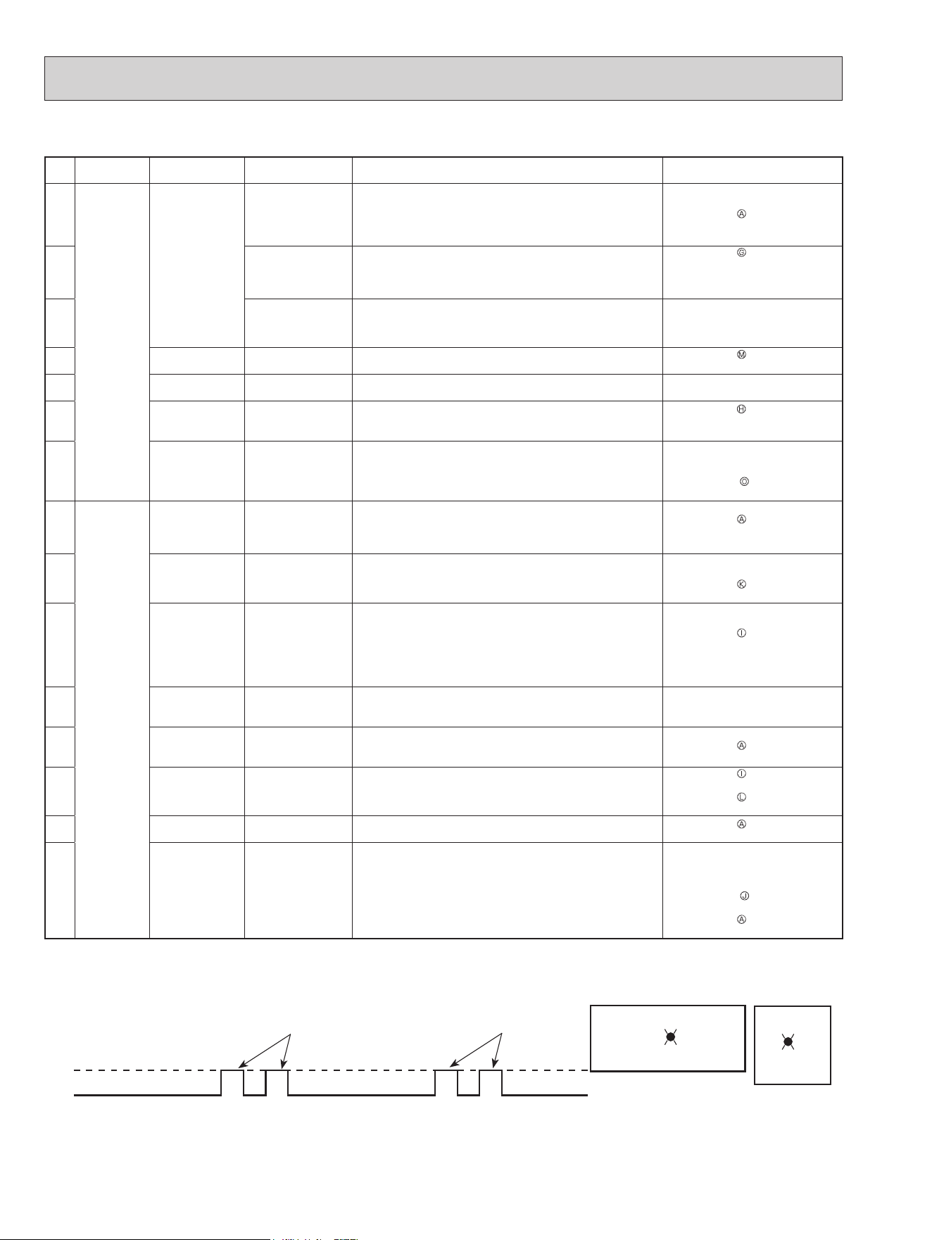
The blinking frequency shows the number of times the LED blinks after every 2.5-second OFF.
(Example) When the blinking frequency is “2”.
ON
OFF
2.5-second OFF
2.5-second OFF
0.5-second ON
0.5-second ON
LED
Blinking →
MUZ-GL09/12/15/18NA
MUZ-GL09/12/15/18NAH
MUY-GL09/12/15/18NA
Inverter P.C. board
MUZ-GL24NA
MUZ-GL24NAH
MUY-GL24NA
LED
→
Blinking
OBH733J
Loading ...
Loading ...
Loading ...