
Loading ...
Loading ...
Loading ...
5
MULTIPLE BASEBOARDS WITH ONE THERMOSTAT
Multiple baseboards can be wired in parallel on the same circuit (check national and local
codes for safety requirements). Additional electrical supply wire and cable clamp connectors
are required. The heaters must be in the same room.
The maximum amperage load you can put on one circuit breaker is limited to either 80% of
the circuit breaker capacity, or the maximum amperage rating of the thermostat, whichever
is lower.
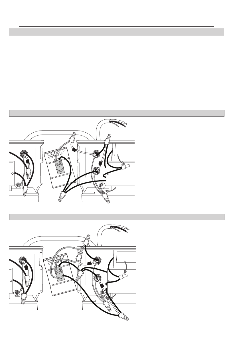
A. Connect one supply wire to the
red thermostat wire.
B. Connect the black thermostat
wire to one wire from each heater.
C. Connect the remaining wire
from each heater to the remaining
supply wire.
D. Make a 3-wire connection with
the two supply ground wires and
the ground screw in heater #1.
For 240 or 208 volt, both black and
white supply wires are hot. Wrap
supply (white) wires with black
tape to identify them as hot!
See Baseboard Owner’s Guide for
baseboard #2 connections.
A. Connect each of the two supply
wires coming directly from the
power supply, to each of the red
thermostat wires.
B. Connect one black thermostat
wire to one wire from each heater.
C. Connect the remaining black
thermostat wire to the remaining
wire from each heater.
D. Make a 3-wire connection with
the two supply ground wires and
the ground screw in heater #1.
For 240 or 208 volt, both black and
white supply wires are hot. Wrap
supply (white) wires with black
tape to identify them as hot!
See Baseboard Owner’s Guide for
baseboard #2 connections.
Cut one factory connection on each baseboard on the side you will be wiring. Two sets of
electrical supply wire go through two cable clamp connectors of baseboard #1. One set of
wires goes to the power supply and the other set goes to baseboard #2.
There are two supply ground wires. You’ll need another short piece of copper wire to make
the 3-wire connection with the ground screw in baseboard #1.
Tuck all the wires back into the individual wiring compartments, and make sure the
connections are tight. Attach with small screw at bottom.
Proceed to OPERATING INSTRUCTIONS.
BTF1
BTF2
A
B
C
A
baseboard #1baseboard #2
wires to
power supply
baseboard #1baseboard #2
wires to
baseboard #2
DO NOT
CUT!
A
B
C
D
D
DO NOT
CUT!
wires to
power supply
wires to
baseboard #2
additional
copper wire
connected
here to
grounding
screw
additional
copper wire
connected
here to
grounding
screw
INSTALLATION INSTRUCTIONS
Loading ...