2413S Rev. 7/20/2012 11:40 AM / See Owner’s Manual for Warranty Information.
Protected under U.S. and foreign patents (see www.insteon.com)
© Copyright 2012 INSTEON, 16542 Millikan Ave., Irvine, CA 92606, 800-762-7845
Quick Start Guide
PowerLinc Modem
TM
– INSTEON
®
Serial Interface (Dual-Band)
Model: 2413S
Install PowerLinc Modem
1) Ensure PowerLinc Modem is not plugged into your computer
2) Plug PowerLinc Modem into an AC wall outlet
3) Plug clear end of included DB-9 serial cable into PowerLinc Modem’s interface port
4) Plug black end of cable into an available serial port on your PC
PowerLinc Modem is now ready
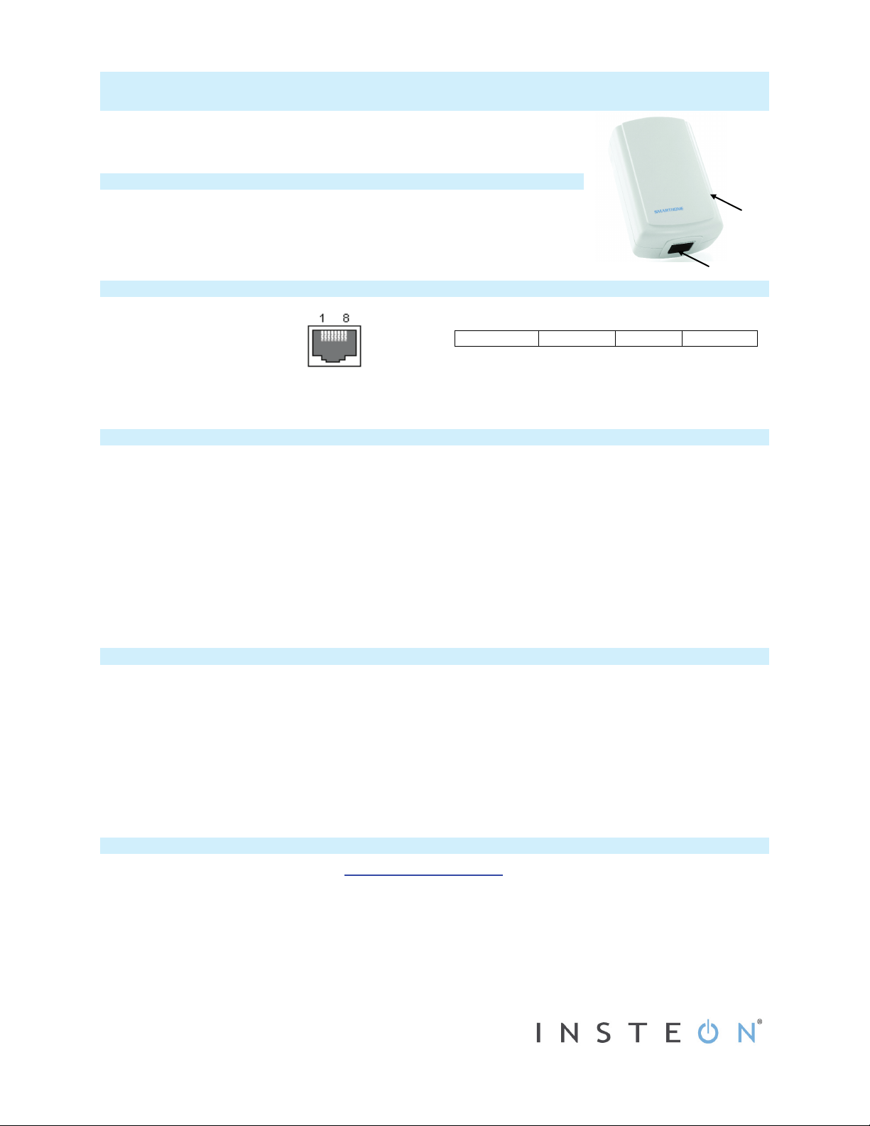
Connector Specifications Communications
Pin 1: RS232 to PC pin 2 (Rx)
Pin 2: Not connected
Pin 3: TTL output (from PLM)
Pin 4: Not connected
Pin 5: Not connected
Pin 6: TTL input (from PLM)
Pin 7: Common ground
Pin 8: RS232 from PC pin 3 (Tx)
Tips for Using PowerLinc Modem
• Do not use a serial cable longer than 10’ (6’ or less is recommended)
• Do not plug PowerLinc Modem into a power strip or AC line filter
• Use only one PowerLinc Modem per computer
• Do not place near large metal objects, such as refrigerators or TVs
• Some computers and their accessories can absorb PowerLinc Carrier (PLC) signals off the powerlines. Since PowerLinc
Modem will be close to the computer, the power strip for the computer should be filtered. Use an INSTEON FilterLinc (#1626-
10) on the computer’s power strip to keep PowerLinc Modem signals from getting absorbed by the computer equipment
• If computer’s serial port is shared with another hardware device (scanner, PDA, etc.) be sure to turn off that device’s program
on the PC. If left running, the home automation software will not be able to communicate with PowerLinc Modem.
• To reset PowerLinc Modem to its original factory settings, unplug from wall outlet and wait 10 seconds. Press and hold Set
button; while continuing to press and hold, plug back in. A long beep will sound; continue holding Set button until beep stops,
then release.
After several seconds, status LED will turn on to indicate reset is complete
Use PowerLinc Modem as a Phase Bridge
1) Install additional dual-band INSTEON devices if they are not already installed
2) Start Phase Detection Mode by tapping the Set button on PowerLinc Modem four times quickly
PowerLinc Modem will begin beeping and status LED will turn on solid green
3) Check the LED behavior of the other dual-band devices to see if they are on the opposite phase
If at least one of the dual-band device LEDs is blinking green or is bright solid white or blue, the device is on the opposite
phase. Continue on to step 4.
If none of the dual-band devices exhibit the behavior above, they are on the same electrical phase. Try the following:
• Follow steps 2 and 3 with the other dual-band devices to see if they are exhibiting the desired LED behavior
• Move a dual-band device to another location until it exhibits the desired LED behavior
4) Tap PowerLinc Modem Set button
PowerLinc Modem will stop beeping
Owner’s Manual and Tech Support
Owner’s Manual and current Quick Start Guide: http://www.insteon.com/support
Call: INSTEON Support Line at 800-762-7845
This device complies with FCC Rules Part 15.Operation is subject to two conditions: (1) This device may not cause harmful interference, and (2) this device must accept any interference that may be received or
that may cause undesired operation. The digital circuitry of this device has been tested and found to comply with the limits for a Class B digital device, pursuant to Part 15 of the FCC Rules. These limits are
designed to provide reasonable protection against harmful interference in residential installations. This equipment generates, uses, and can radiate radio frequency energy and, if not installed and used in
accordance with the instructions, may cause harmful interference to radio and television reception. However, there is no guarantee that interference will not occur in a particular installation. If this device does
cause such interference, which can be verified by turning the device off and on, the user is encouraged to eliminate the interference by one or more of the following measures:
• Reorient or relocate the receiving antenna of the device experiencing the interference.
• Increase the distance between this device and the receiver.
• Connect the device to an AC outlet on a circuit different from the one that supplies power to the receiver.
• Consult the dealer or an experienced radio/TV technician.
WARNING! Changes or modifications to this unit not expressly approved by the party responsible for compliance could void the user's authority to operate the equipment.
Interface Port
The RS 232 serial communications to PowerLinc
Modem are:
19,200 baud
8 data bits
No parity
1 stop bit
NOTE: each byte sent to PowerLinc Modem will be
echoed back to the host.
Interface Port
Set button