
www.LaViewSecurity.com2

www.LaViewSecurity.com 1
Table of Contents
Chapter 1 Introduction................................................................................................................................. 2
1.1Front Panel
1.2Rear Panel
1.3IR Remote Control Operations
1.4USB Mouse Operation
Chapter 2 Getting Started........................................................................................................................... 4
2.1 Starting Up and Shutting Down the DVR
2.2 Adding and Connecting the IP Cameras
Chapter 3 Live View..................................................................................................................................... 9
3.1 Introduction of Live View
3.2 Operations in Live View Mode
3.3 Adjusting Live View Settings
Chapter 4 PTZ Controls............................................................................................................................. 11
4.1ConguringPTZSettings
4.2SettingPTZPresets,Patrols&Patterns
Chapter 5 Record Settings......................................................................................................................... 13
5.1ConguringEncodingParameters
5.2ConguringRecordSchedule
5.3ConguringMotionDetectionRecord
5.4 Manual Record
Chapter 6 Playback.................................................................................................................................... 17
6.1 Playing Back Record Files
6.2 Smart Search
6.3DigitalZoom
Chapter 7 Backup....................................................................................................................................... 22
7.1 Backup Up Footage Files
Chapter 8 Network Settings....................................................................................................................... 25
8.1ConguringGeneralNetworkSettings
8.2ConguringAdvancedNetworkSettings
8.3 Setup Remote View On Mobile Devices
Chapter 9 Hard Drive Management......................................................................................................... 28
9.1 Initializing HDDs
9.2ManagingNetworkHDD
9.3ManagingHDDGroup
Chapter 10 Camera Settings...................................................................................................................... 31
10.1ConguringOSDSettings
10.2ConguringPrivacyMask
10.3ConguringVideoParameters
Chapter 11 DVR Management and Maintenance................................................................................... 32
11.1 Viewing System Information
11.2Searching&ExportLogFiles
11.3 Upgrading System
11.4 Restoring Default Settings
Chapter 12 Others...................................................................................................................................... 35
12.1ConguringGeneralSettings
12.2ConguringDSTSettings
12.3 Managing User Accounts
FAQ.............................................................................................................................................................. 38
www.LaViewSecurity.com2
ThankyouforpurchasingtheLaViewPremiumDigitalVideoRecorderSystem!YourLaViewSystem
representsthelatestinhomesurveillancetechnology,providingyouwithstate-of-the-artvideorecording
inanaordable,user-friendlypackage.AtLaView,wewanttoensurethatyourhomeorbusinessis
reliablyprotected.Thisuserguideisdesignedtohelpyouaccessallbasicfeaturesyoumayneedtofully
safeguardyourestate.*(ManualsfordierentLaViewsystems/devicesmaydier.)Forinstructiononthe
completerangeoffeatures,pleaserefertothediscthataccompaniesyoursystem,orbygoingonlineto
www.LaViewSecurity.com/support.
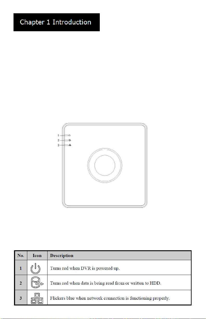
Front Panel
Description of Control Panel Buttons
www.LaViewSecurity.com 3
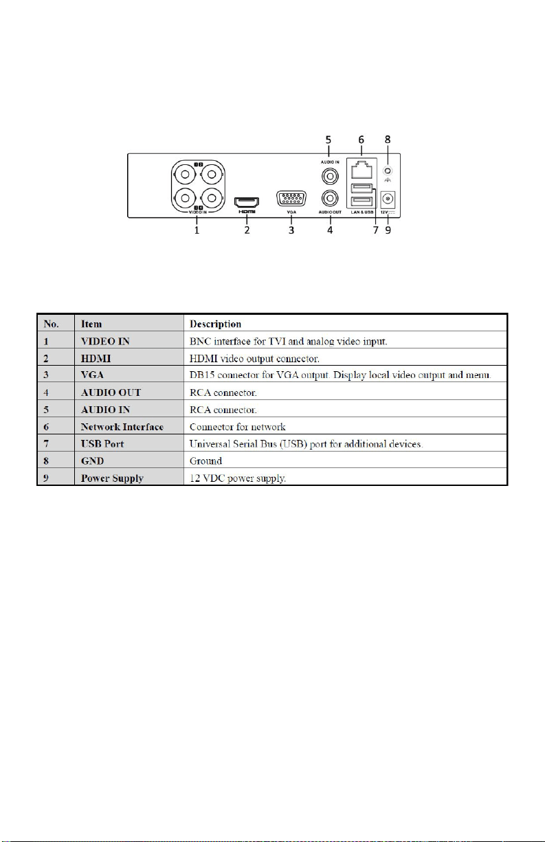
Rear Panel
Description of Rear Panel Interfaces
USB Mouse Operation
Aregular3-button(Left/Right/Scroll-wheel)USBmousecanalsobeusedwiththisDVR.TouseaUSB
mouse:
1. Plug USB mouse into one of the USB interfaces on the front panel of the DVR.
2. Themouseshouldautomaticallybedetected.Intherarecasethatthemouseisnotdetected,the
possiblereasonmaybethatthetwodevicesarenotcompatible,pleaserefertotherecommended
device list from your provider.
www.LaViewSecurity.com4
Starting Up and Shutting
Down the DVR
Before you start:
Checkthatthevoltageoftheextrapowersupplyis
thesameastheDVR’srequirement,andtheground
connection is working properly.
Starting up the DVR:
Steps:
1. Check that the power supply is plugged
into an electrical outlet. It is HIGHLY
recommended that an Uninterruptible Power
Supply(UPS)beusedinconjunctionwiththe
device.
2. Turnonthepowerswitchontherearpanel.
3. Afterstartup,thePowerLEDindicatorturns
on . A splash screen with the status of the
HDD appears on the monitor. The row of
icons at the bottom of the screen shows the
HDD status. ‘X’ means that the HDD is not
installed or cannot be detected.
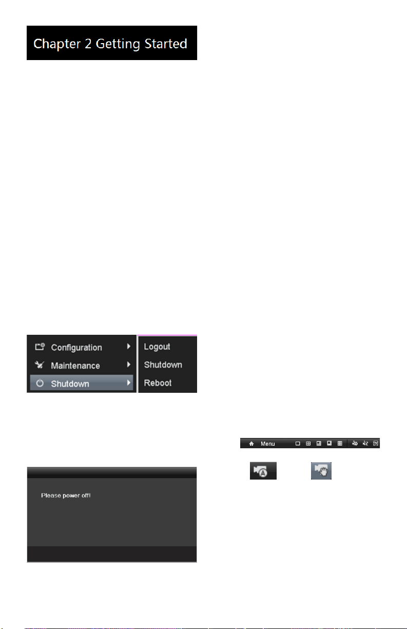
Shutting down the DVR
Steps:
1. EntertheShutdownmenu.
Menu > Shutdown
Shutdown Menu
2. Click the Shutdown button.
3. Click the Yes button.
4. Turnothepowerswitchontherear
panel when the Prompt pops up.
Shutdown Prompt
Rebooting the DVR
IntheShutdownmenu,youcanalsorebootthe
DVR.
Steps:
1. EntertheShutdown menu by clicking
Menu > Shutdown.
2. Click the Logout button to lock the DVR
or the Reboot button to reboot the DVR.
Password
ThedefaultpasswordfortheDVRis12345.
Innewerrmware,youmaybeaskedtocreate
yourownpasswordthersttimeyouturnon
the system. Please contact our tech support if
you do not remember your password.
Adding and Connecting IP
Cameras
Adding the Online IP Cameras
Purpose:
TheDVRsupports1bonusIPChanneltoconnect
to select LaView 1080P IP Camera. Before you can
getlivevieworrecordedvideo,youshouldadd
the network cameras to the connection list of the
device.
Before you start:
Ensurethatthenetworkconnectionisvalidand
correct.Fordetailedcheckingandconguring
ofthenetwork,pleaseseeChapter Checking
Network Trac and Chapter Conguring Network
Detection.
Option 1:
Steps:
1. Right-click the mouse when you are in live
view mode to show the menu bar.
2. Select (Auto) or (Manual).
• Auto
The device willadd thedetected IP cameras
or encoders automatically by using the admin
user name and password.
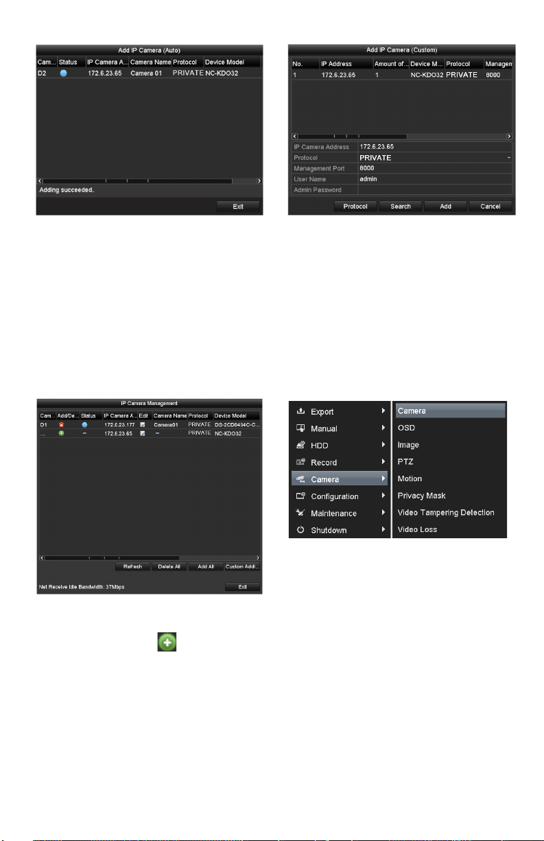
www.LaViewSecurity.com 5
Auto Adding IP Camera Interface
Note: If the user name and password are
changed, the auto adding of IP camera may
fail. you may add it manually if necessary.
• Manual
Steps:
1. To add online cameras with same
network segment:
1) Thedetectedonlinecamerawillbe
listedinthe cameralist,asshown
inthegurebelow.
Manual Adding IP Camera Interface
2) Click the button to add the
camera.
2. ToaddotherIPcameras:
1) Click the Custom Adding button
toseetheAddIPCamera(Custom)
interface.
Manual Adding IP Camera Interface
2) You can edit the IP address,
protocol, management port,
and other information for the IP
camera.
3) Click Add to add the camera.
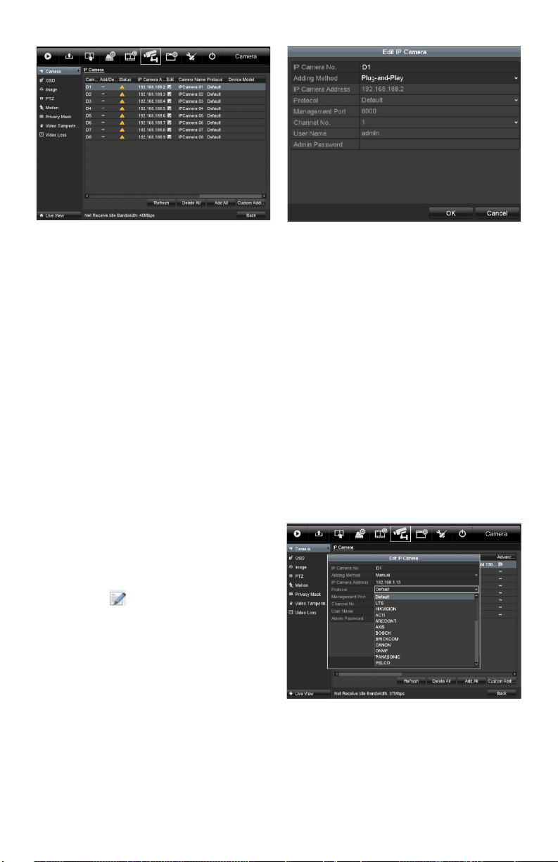
Option 2:
Steps:
1. EntertheCameraManagementinterface.
Menu> Camera> Camera
Menu
2. To add online cameras with same network
segment:
1) Click Search to search for online
cameras.
www.LaViewSecurity.com6
Camera Settings Interface
2) Check the box next to cameras tobe
added.
3) Click Quick Add to add the camera.
3. ToaddotherIPcameras:
1) Ontheleftsideoftheinterface,you
canentertheIPaddress,protocol,
managementport,username,
password and other information for
the IP camera.
2) Click Add to add the camera.
Note: If you check the Synchronize IP
Cameracheckbox,thedefaultsettings
of the DVR for IP cameras is applied to
the added camera.
Editing the Connected IP
cameras and Configuring
Customized Protocols
AftertheIPcamerasareadded,thebasicinformation
of the camera will show in the page, you can
congurethebasicsettingsoftheIPcameras.
Steps:
1. Click the icon to edit the parameters; you
can edit the IP address, protocol and other
settings.
Edit the Parameters
2. Click apply to save the settings and click OK
toexittheeditinginterface.
Conguring customized protocols
Purpose:
Toconnectthenetworkcameraswhicharenot
conguredwithstandardprotocols,youcan
congurecustomizedprotocolsforthem.
Steps:
1. Choose the protocol type and choose the
transfer protocols.
Note: Theprotocoltypeandthetransferprotocols
must be supported by the connected network
camera.
Afteraddingcustomizedprotocols,youcanseethe
protocol name listed in the dropdown list.
Protocol Setting
2. Choose the protocols you just added to
validate the connection of the network
camera.
www.LaViewSecurity.com 7
Editing IP Cameras connected
to the PoE interfaces (applicable
models only)
ThePoEinterfaceenablestheDVRsystemtopass
electricalpoweranddata,throughEthernetcabling
to the connected network cameras.
LaView DVRsprovides PoEinterfaces whichcan
connect to network cameras directly; and if you dont
usethe PoE interface, youcanalso connect tothe
onlinenetworkcameras.ThePoEinterfacesupports
thePlug-and-Playfunction.
Example:
For LaView DVRs, when you want to connect 1
online camera and connect 3 network cameras via
PoEinterfaces,youmustdisable1PoEinterfacein
the Edit IP camera panel.
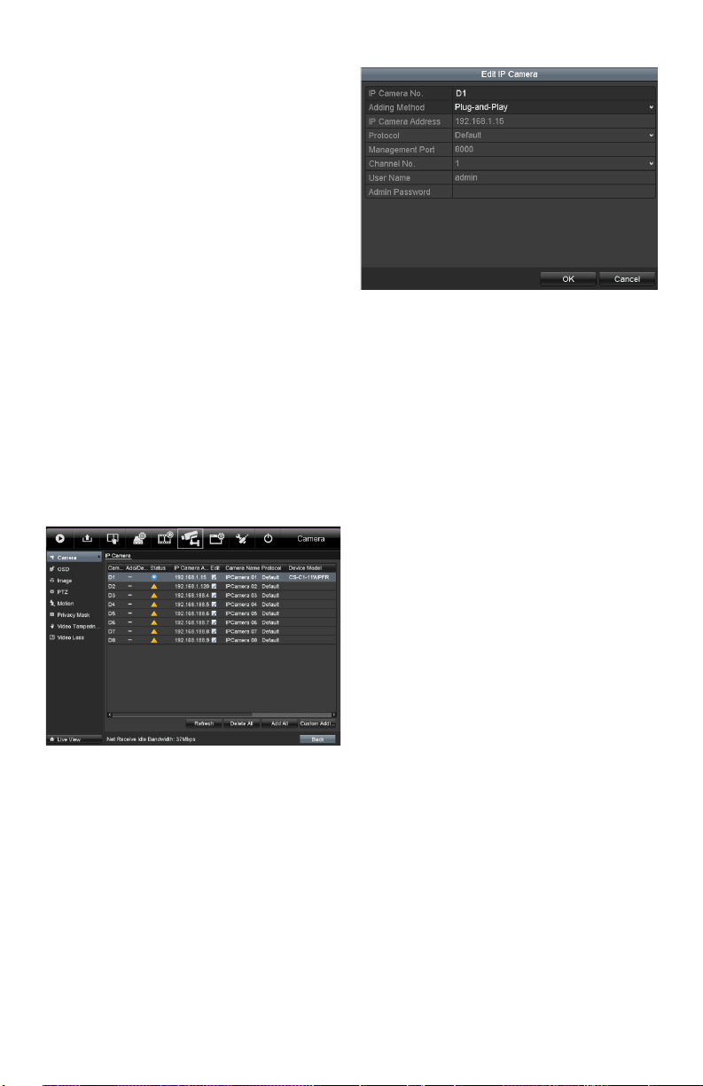
To add Cameras for DVR supporting PoE
function:
Before you start:
Connect the network cameras using the PoE
interfaces.
Steps:
1. EntertheCameraManagementinterface.
Main menu> Camera> Camera
Theconnectedcamerasarelisted.
List of Connected Cameras
Edit IP Camera Interface
Note: Plug-and-Playmeansthatthecamerais
connectedtothePoEinterface.Theparameters
ofthecameracan’tbeeditedhere.TheIPaddress
ofthecameracanonlybeeditedintheNetwork
Congurationinterface,seeChapter Conguring
General Settings for detailed information.
Editing IP cameras connected
to the built-in switch network
interfaces (applicable models
only)
In LaView DVRs, the extra network interfaces
provide a built-in switch with plug-and-play
function.
Example:
When you want to connect 2 online cameras and 6
networkcamerasviabuilt-inswitchinterfaces,you
mustdisable2built-inswitchinterfacesintheEdit
IP camera panel.
To add Cameras for DVR via built-in switch
interfaces:
Before you start:
Connectthenetworkcamerasviathebuilt-inswitch
interfaces.
Steps:
1. EntertheCameraManagementinterface.
Main menu> Camera> Camera
Theconnectedcamerasshouldbelisted.
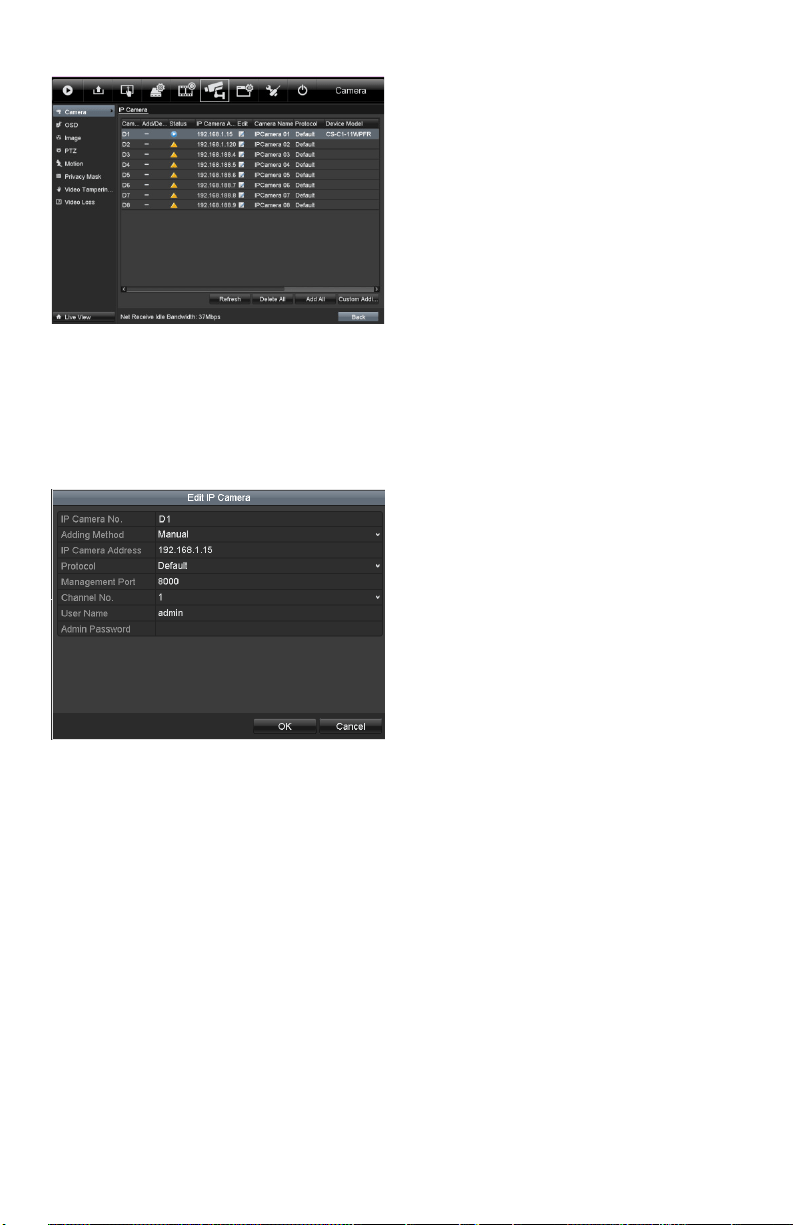
www.LaViewSecurity.com8
List of Connected Cameras
Note: The cameras connected to the built-
in switch interface cannot be deleted in this
menu.
2. Click the Edit button.
Edit IP Camera Interface
Note: Plug-and-Play means that the camera
is connected to the switch interface. The
parameters of the camera can’t be edited
here.TheIPaddressofthecameracanonly
be edited in the Network Conguration
interface.
www.LaViewSecurity.com 9
Introduction of Live View
Live view shows you the video captured by each
camerainrealtime.TheDVRautomaticallyenters
Live View mode when powered on.
Live View Icons
Intheliveviewmode,thereareiconsatthetopright
ofthescreen,showingthestatusofeachchannel,so
thatyoucanseewhetherthechannelisrecording,or
whether there are alarms are being triggered.
Operations in Live View
Mode
Inliveviewmode,therearemanyfunctions
provided.Thefunctionsarelistedbelow.
• Single Screen: Showing only one screen on
the monitor.
• Multi-screen: Showing multiple screens on
the monitor simultaneously.
• Auto-switch:Thescreenisautoswitched
tothenextone.Youmustsetthedwelltime
foreachscreenonthecongurationmenu
beforeenablingauto-switch.
Menu>Conguration>LiveView>General.
• Start Recording: Normalrecordandmotion
detection record are supported.
• Output Mode: Select the output mode to
Standard,Bright,GentleorVivid.
• All-day Playback: Playback the recorded
videos for the selected day.
Using the Mouse in Live
View
Mouse Operation in Live View
Note: Thedwell timeoftheliveviewconguration
must be set before using Start Auto-switch.
Note: RebootIntelligenceisenabledwhenright-
clickingonacameraaslongas,thecorresponding
camera supports intelligent function
Right-click Menu
Note:
Two ways to show the Right-click Menu
Bar: right-clicking or moving the mouse to
the bottom of the screen.
You can click on the right side of the
menu bar to clip the menu on the screen.
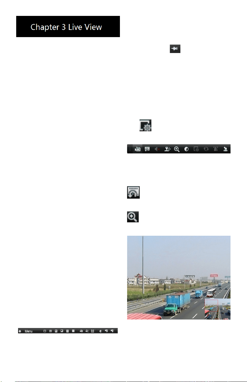
Quick Setting Toolbar in
Live View Mode
On the screen of each channel, there is a quick
setting toolbar which shows up when you single
click the mouse in the one of the camera views.
Note: Live View Strategy is only available for
network cameras.
Quick Setting Toolbar
Description of Quick Setting Toolbar Icons
InstantPlaybackonlyshowsthelastve
minutes.Ifnorecordingisfound,itmeansthere
wasnorecordingduringthelastveminutes.
DigitalZoomcanzoominonaselectedarea
Left-clickanddrawtoselecttheareatozoomin.
Digital Zoom
www.LaViewSecurity.com10
Adjusting Live View
Settings
Purpose:
Live View settings can be customized according to
yourneeds.Youcanconguretheoutputinterface,
dwelltimeforeachchannel,mute/volumefor
audio,thescreennumberforeachchannel,etc.
Steps:
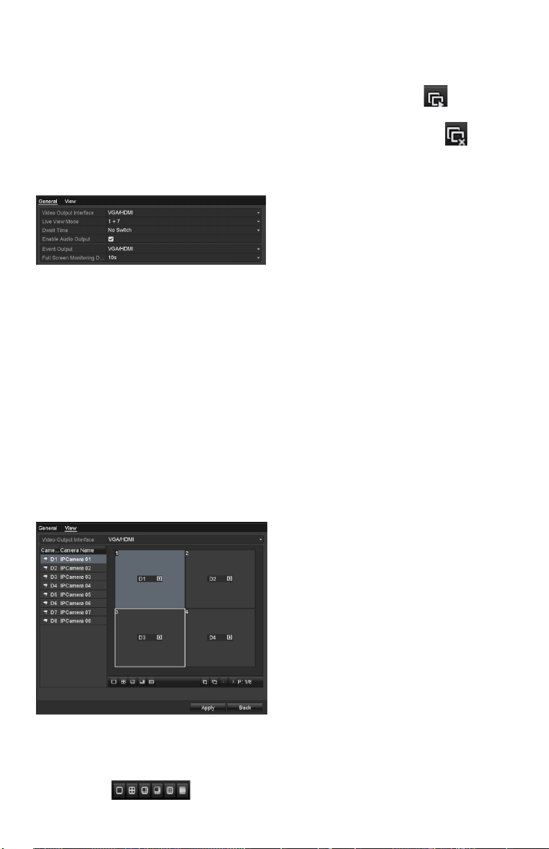
1. EntertheLiveViewSettingsinterface.
Menu>Conguration>LiveView
Live View-General
Thesettingsavailableinthismenuinclude:
• Video Output Interface: Designates the
outputtobeusedoptionsincludeVGA/
HDMI.
• Live View Mode: Designates the display
mode to be used for Live View.
• Dwell Time: Thetimeinsecondsbetween
switchingofchannelswhenauto-switchis
enabled in Live View.
• Enable Audio Output: Enables/disables
audio output for the selected video output.
• Event Output: Designates the output where
to show event video.
• Full Screen Monitoring Dwell Time: The
time in seconds to show an event on screen.
2. Setting order of cameras
Live View- Camera Order
Tosetthecameraorder:
1) Select a View mode
.
2) Selectthesmallbox,anddouble-
click on the camera number
to display that channel on the
window.
Youcanclick button to
enable live view for all the
channels and click to stop
live view.
3) Click the Apply button to save the
settings.
www.LaViewSecurity.com 11
Conguring PTZ Settings
Purpose:
FollowtheproceduretosettheparametersforPTZ.
TheconguringofthePTZparametersmustbe
donebeforeyoucancontrolthePTZcamera.
Steps:
1. EnterthePTZSettingsinterface.
Menu>Camera>PTZ
PTZ- General
2. Choose the camera in the Camera
dropdown list.
3. EntertheparametersofthePTZcamera.
Note: AlltheparametersshouldbeinthePTZ
camera parameters section of the camera manual.
Example:IfthePTZcamerausesthe
protocolofDRAGON,youshouldselect
DRAGONinthePTZProtocoleld.
4. Click Apply button to save the settings.
Setting PTZ Presets,
Patrols & Patterns
Before you start:
Pleasemakesurethatthepresets,patrolsand
patternsarebesupportedbyPTZprotocols.
Customizing Presets
Purpose:
FollowthestepstosetthePresetlocation,whichis
whereyouwantthePTZcameratopointwhenan
event takes place.
Steps:
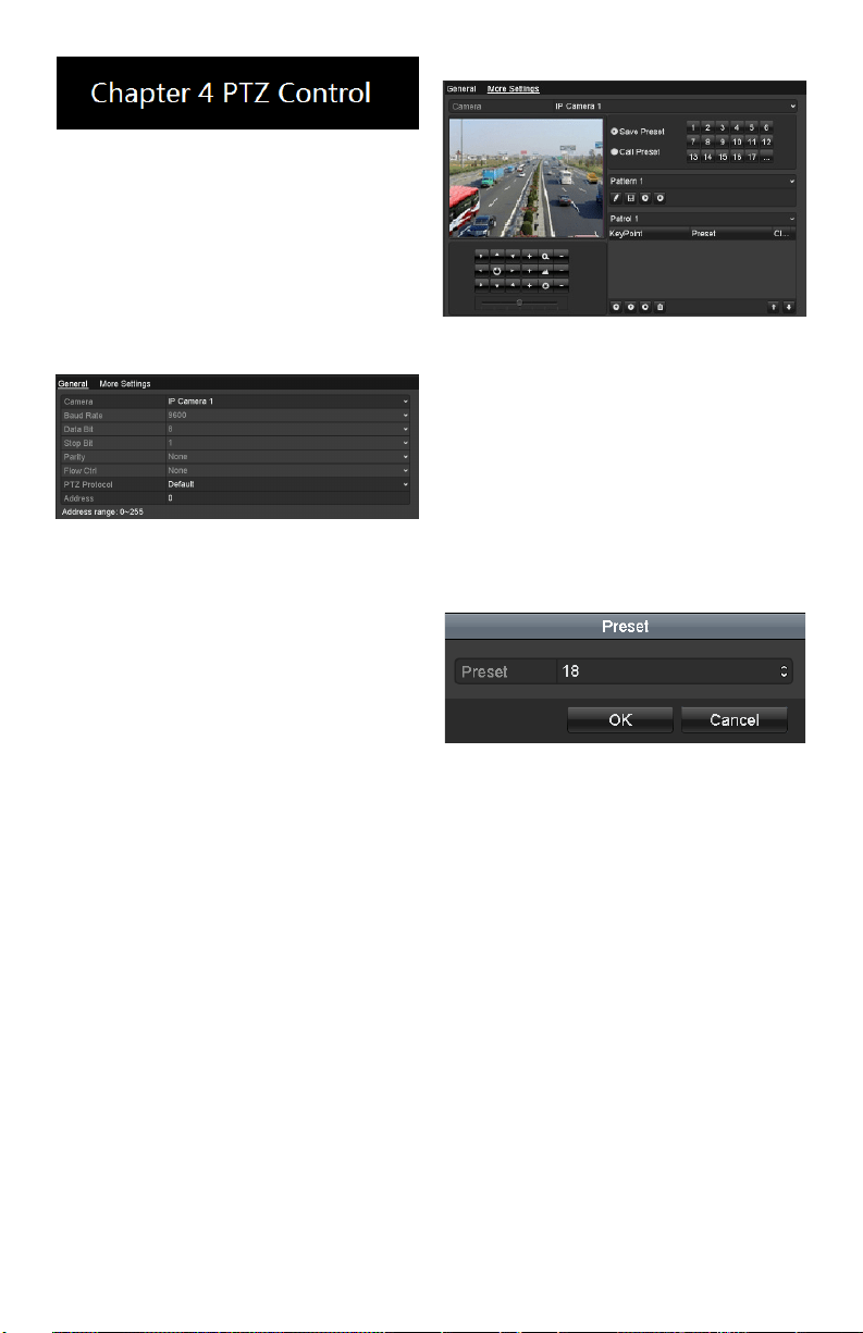
1. EnterthePTZControlinterface.
Menu>Camera>PTZ>MoreSettings
PTZ-MoreSettings
2. Use the directional button to wheel the
camera to the location that you want to as preset.
3. ClicktheroundiconnexttoSave
Preset.
4. Click the preset number to save the
preset.
Repeatthesteps2-4tosavemorepresets.Ifthe
number of the presets you want to save is more
than17,youcanclick[…]andchoosetheavailable
numbers.
More Presets
Calling Presets
Purpose:
Thisfeatureenablesthecameratopointtoa
speciedpositionsuchasawindowwhenapreset
is needed.
Call preset in the PTZ setting interface:
Steps:
1. EnterthePTZControlinterface.
Menu>Camera>PTZ>MoreSettings
2. Check the round icon of Call Preset.
www.LaViewSecurity.com12
PTZ-CallPreset
3. Choose the preset number.
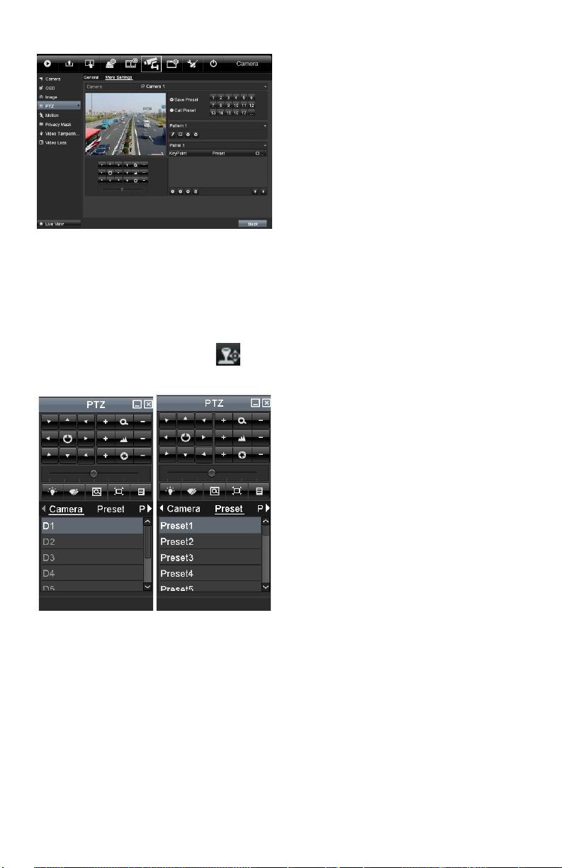
Call preset in live view mode:
Steps:
1. PressthePTZbuttononthefrontpanel
orclickthePTZControlicon in the
quicksettingbartoenterthePTZsetting
menu in live view mode.
PTZToolbar
2. Choose Camera in the list on the menu.
3. Double click the preset in the Preset list
to call it.
Thecamerawillmovetothesaved
location from the preset selected.
www.LaViewSecurity.com 13
Conguring Encoding
Parameters
Purpose:
By conguring the encoding parameters you can
adjustimagequality,throughchangingtransmission
streamtype,resolution.etc.
Before you start:
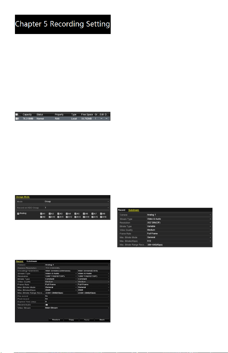
Make sure that the HDD has already been installed.
If not, please install a HDD and initialize it.
(Menu>HDD>General)
HDD-General
Check the storage mode of the HDD:
Click Advanced to check the storage mode of the
HDD.
If the HDD mode is Quota,pleasesetthemaximum
record capacity and maximum picture capacity.
For detailed information, see Chapter Conguring
Quota Mode.
If the HDD mode is Group, you should set the
HDDgroup.Fordetailedinformation,seeChapter
Conguring HDD Group for Recording.
HDD-Advanced
Steps:
EntertheRecordsettingsinterfacetocongurethe
encoding parameters:
Menu>Record>Encoding
RecordEncoding
EncodingParametersforRecording
Select Record tab page to congure stream type,
resolution,andotherparametersasneeded.
Pre-record: The amount of time to be recorded
priortoanalarm-triggeredevent.Forexample,if
youset thepre-record timeas5 seconds,when an
alarmtriggersrecordingat10:00,thecamerasaves
video starting at 9:59:55.
Post-record:Thetimeyousettoberecordedafter
the event. For example, if you set the post-record
time as 5 seconds, when an alarm triggered the
recordingendsat11:00,itcontinuesrecordingtill
11:00:05.
Expiration Time: Expired time, is the amount of
timeforarecordletobekeptintheHDD.Ifthe
deadlineisreached,thelewillbedeleted.Youcan
settheexpiredtimeto0,andthenleswillneverbe
deleted.Storagetimeforlesshouldbedetermined
by the capacity of the HDD.
Redundant Record: Enabling redundant record
means the recording is saved in the redundant HDD.
See Chapter Conguring Redundant Recording.
Record Audio: Check the checkbox to enable or
disable audio recording.
Click Apply to save the settings.
EncodingParametersSettingsforSub-stream
EntertheSub-streamtabpage.
Sub-streamEncoding
Conguretheparametersofthecamera.
Click Apply to save the settings.
Conguring Record
Schedule
Purpose:
Set the recording schedule for the camera to
automatically start/stop recording according to the
conguredschedule.
Steps:
EntertheRecordScheduleinterface.
www.LaViewSecurity.com14
Menu>Record>Schedule
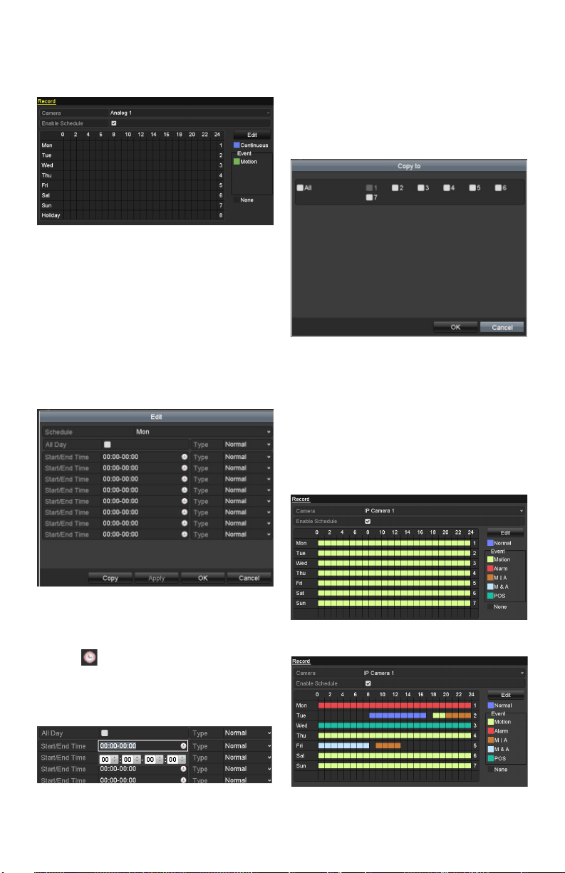
CongureRecordSchedule
Select Record Schedule.
Record Schedule
Choosethecamerayouwanttocongure.
checkthecheckboxnexttoEnable Schedule item.
Click Edit button or click the icon under the edit
button and click and drag the schedule desired on
the panel.
Edit the schedule:
Inthemessagebox,youcanchoosethedaytowhich
you want to set schedule.
Recording Schedule Interface
Click the button to set a recording schedule.
Toscheduleall-dayrecording,checkthecheckbox
nexttoAll Day.
EditSchedule
To arrange any other schedule, leave the All Day
checkboxblankandsettheStart/Endtime.
Note: Up to 8 periods can be congured for each
day.Thetimeperiodscannotbeoverlapped.
Repeat these steps to schedule recording for other
days of the week. If the schedule can also be applied
tootherdays,click Copy.
Copy Schedule to Other Days
Click OK to go back to upper level menu.
Click Apply in the Record Schedule interface to
save the settings.
Draw the schedule:
Click on the color icons, you can choose the
scheduled recording type as normal or event
triggered.
Draw the Schedule
www.LaViewSecurity.com 15
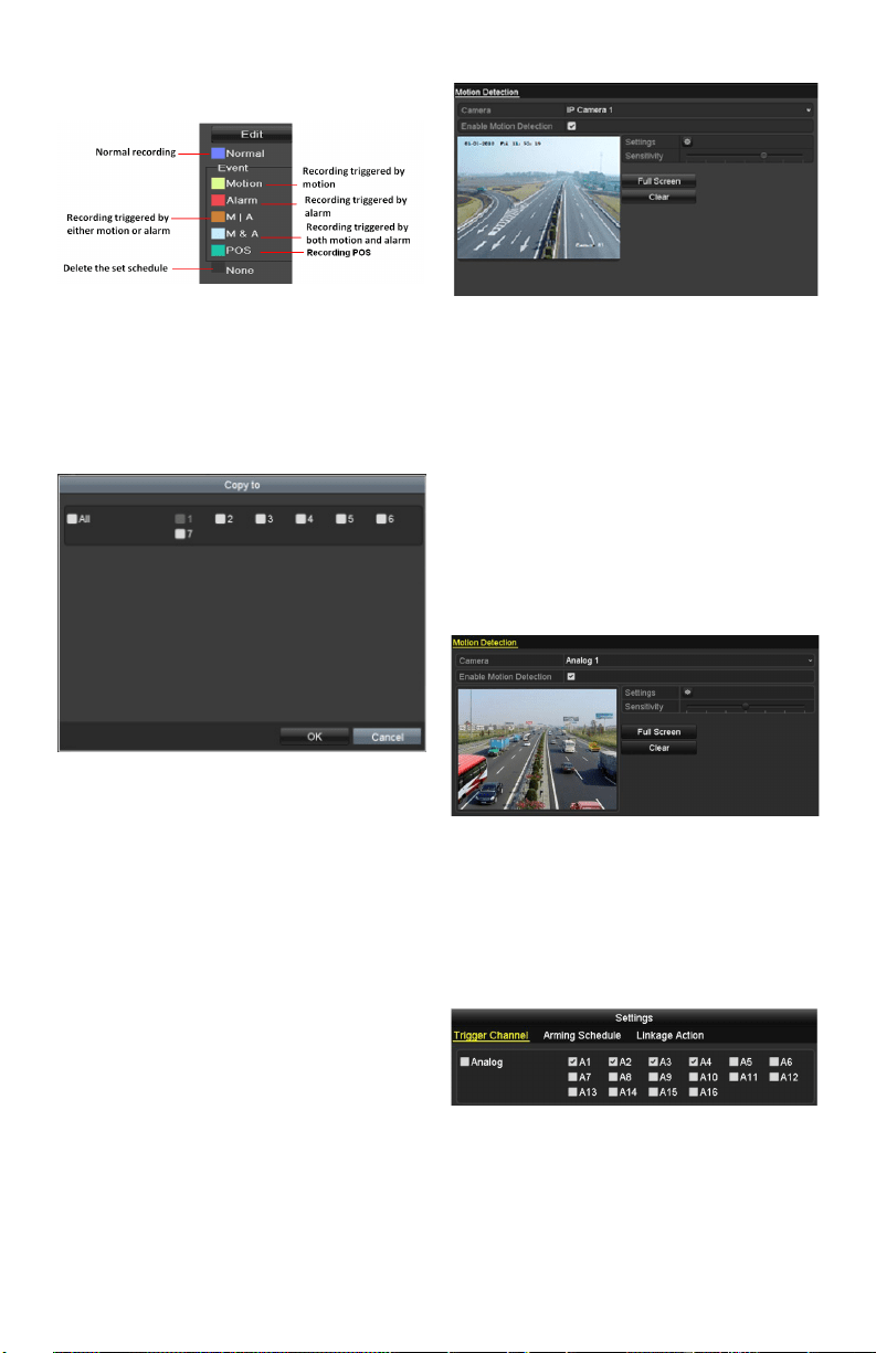
Descriptions of the scheduled recording icons are
showninthegurebelow.
Descriptions of the scheduled recording icons
Click the Apply button to validate the settings.
Ifyouwishtousethesesettingsforotherchannels,
click Copy,thenchoosethe channelto whichyou
want to copy the settings.
Copy Schedule to Other Channels
Conguring Motion
Detection Record
Purpose:
Follow these steps to set the motion detection
parameters. In live view mode, when a motion
detection event takes place, the DVR can analyze
it and carry out a variety of actions to handle it.
Enabling motion detection function can trigger
certain channels to start recording, full screen
monitoring, audio warning, notify the surveillance
center etc.
Steps:
EntertheMotionDetectioninterface.
Menu>Camera>Motion
Motion Detection
CongureMotionDetection:
Choosecamerayouwanttocongure.
Check the checkbox next to Enable Motion
Detection.
Crop the area for motion detection by mouse. If you
want to set motion detection for the area shot by the
camera,clickFull Screen.Tostartover,
click Clear.
MotionDetection-Grid
Click Setting to select channels that will link to the
motion detection trigger.
Motion Detection Settings
Select the channels for which you want the motion
detection event to trigger recording.
Click Apply to save the settings.
Click OK to go back to menu.
ExittheMotionDetectionmenu.
Fordetailedinformationonscheduleconguration,
www.LaViewSecurity.com16
see Chapter Conguring Record Schedule.
Manual Record
Purpose:
Follow the steps to set parameters for manual
recording.
Steps:
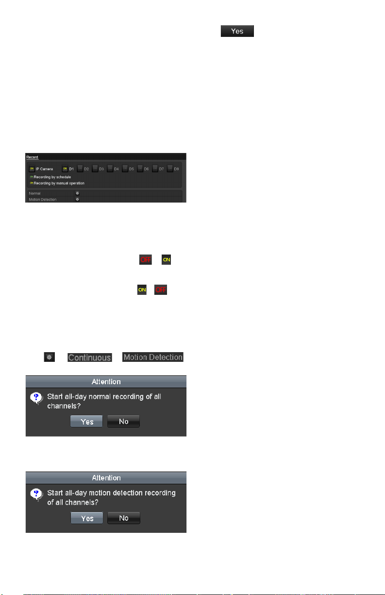
EntertheManualsettingsinterface.
Menu> Manual
Or press the REC button on the remote control.
Manual Record
EnablingManualRecord:
Select Record on the left bar.
Nexttothecameranumber,change to .
Disabling manual record:
Nexttothecameranumber,change to .
Note: After rebooting, all manual records enabled
are canceled.
Startall-daycontinuousrecordingorall-daymotion
detection recording of all channels:
Click for or .
Continuous Recording
Motion Detection Recording
Click to enable all-day continuous
recordingorall-daymotiondetectionrecordingon
all channels.
www.LaViewSecurity.com 17
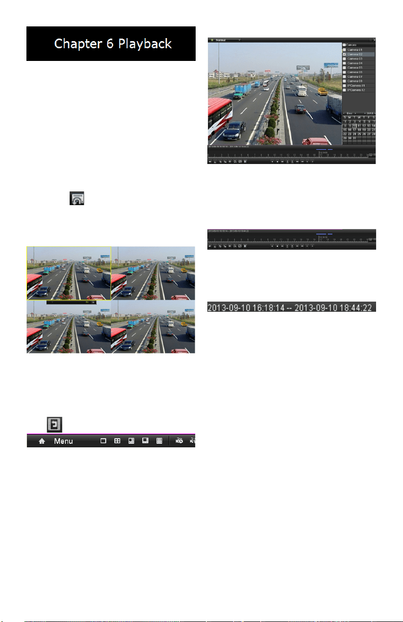
Playing Back Record Files
Playing Back by Channel
Purpose:
Play back the recorded video les of a specic
channel in live view mode. Channel switch is
supported.
OPTION 1:
Choose a channel in live view mode using the mouse
and click the button in the quick setting toolbar.
Note: Ininstantplaybackmode,onlylesrecorded
duringthelastveminutesonthischannelwillbe
played back.
Instant Playback Interface
OPTION 2:
EnterthePlaybackinterface.
Mouse: right click a channel in live view mode and
select from the menu.
Right-clickMenuunderLiveView
Front Panel: press PLAY button to play back
recordedlesfromthechannelundersingle-screen
live view mode.
Whenonmulti-screenliveviewmode,therecorded
lesfromthetop-leftchannelwillbeplayedback.
Note: During playback process, pressing the
numerical buttons will switch playback to the
corresponding channels.
Playback management:
ThetoolbaronthebottomofthePlaybackinterface
can be used to control playing progress.
Playback Interface
Clickonmultiplechannel(s)toexecutesimultaneous
playback.
ToolbarofPlayback
Note:
indicatesthestart/endtimeofrecording.
DetailedExplanationofPlaybackToolbar
Note: Playback progress bar: Use the mouse to click
on point in the progress bar or drag the progress bar
tolocatespecicframes.
Playing Back by Time
Purpose:
Play back video les recorded in specied time
duration.Multi-channelsimultaneousplaybackand
channel switch are supported.
Steps:
Enterplaybackinterface.
Menu>Playback
Check o channel(s) in the channel list and then
double-clicktoselectadateonthecalendar.
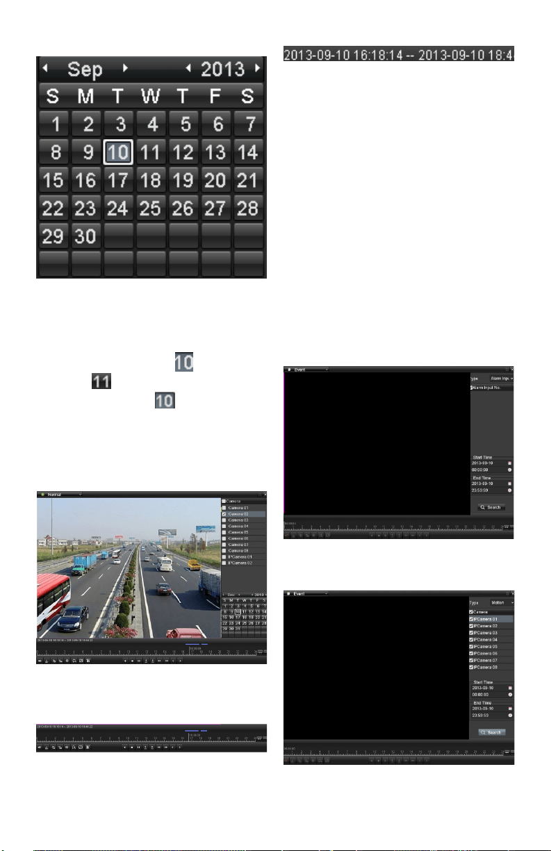
www.LaViewSecurity.com18
Playback Calendar
Note:
Ifa camera has recordings fromthatday, theicon
in the calendar is displayed as . Otherwise it is
displayed as . The selected date is surrounded
byawhiterectangle,asin .
In the Playback interface:
ThetoolbaratthebottomofthePlaybackinterface
can be used to control playing progress.
InterfaceofPlaybackbyTime
ToolbarofPlaybackbyTime
Note: The
indicatesthestart/endtimeoftherecording.
Detailed Explanation of Playback-by-time
Interface
Note:
Playback progress bar: Use the mouse to click on
any point in the progress bar or drag the progress bar
tolocatespecicframes.
Playing Back by Event Search
Purpose:
Playbackspecicles onone orseveral channels
by restricting event type (e.g. alarm input and
motiondetection).
Steps:
EnterthePlaybackinterface.
Menu>Playback
Select Eventinthedrop-downlistonthetop-left.
Select Alarm Input or Motion as the event type and
settheStarttimeandEndtime.
Alarm Input Search Interface
Motion Search Interface
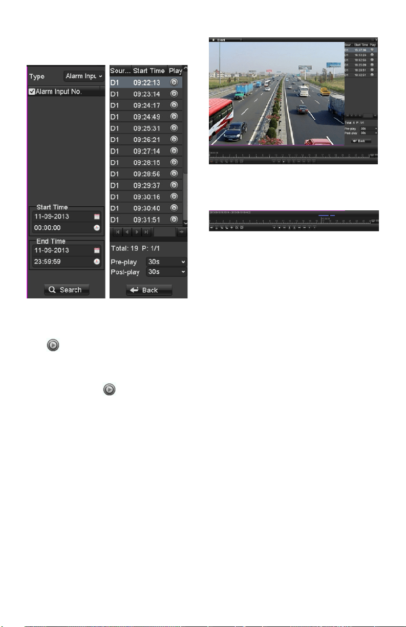
www.LaViewSecurity.com 19
Click the Search button to get search results from
theinformationprovided.Refertoright-sidebarfor
results.
SearchResultBar(AlarmInandMotion)
Click buttontoplaybackthele.
Note:
Pre-playandpost-playcanbecongured.
If the event is set to trigger recording on multiple
channels,clickingthe will activate the Synch
Playbackinterface.You can select whichchannels
to play back synchronously.
Click the Back button to go back to the search
interface.
Playback interface:
ThetoolbaratthebottomofthePlaybackinterface
can be used to control playing progress.
InterfaceofPlaybackbyEvent
ToolbarofPlaybackbyEvent
Detailed Explanation of Playback-by-Event
Toolbar
Note:
Playback progress bar: Use the mouse to click on
any point in the progress bar or drag the progress bar
tolocatespecicframes.
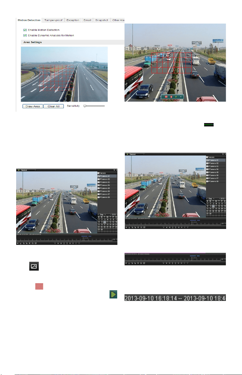
Smart Search
Purpose:
In order to locate motion detection events easily in
theplaybackprogressbar,youcananalyzeacertain
area/scenetogetalloftherelatedmotiondetection
events that occurred in the area.
Note: Thesmartsearchfunctionmayvaryaccording
to the camera connected to the DVR.
Before you start:
Loginthenetworkcamerausingyourwebbrowser,
and enable the Dynamic Analysis for Motion by
checkingthecheckboxnexttoit.Enterthemotion
detectioncongurationinterface:
Conguration>Advanced Conguration> Events>
Motion Detection.
www.LaViewSecurity.com20
Motion Detection Settings
Enable the motion detection function and set the
arming area to full screen using the DVR’s local
menu.
Steps:
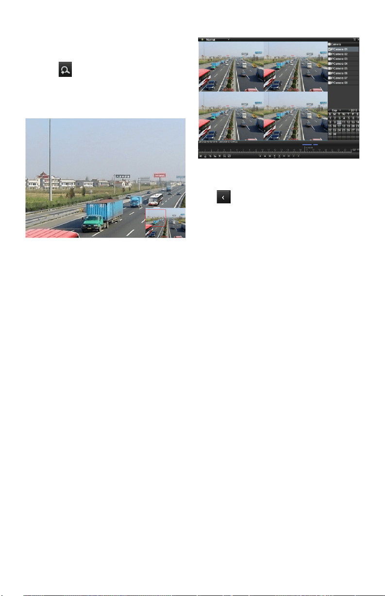
EnterthePlaybackinterfaceandplayarecordle.
InterfaceofPlaybackbyTime
Click on the playback toolbar to enter Smart
Search mode.
Clickanddragthemousetocropanarea.Youcan
click the button to set the whole screen as a
search area.After cropping an area, click the
buttontoexecutesmartsearchinthisarea.
Note: Multi-areasearchingmodesaresupported.
Crop of Smart Search Area
Smartsearchndingswillbemarkedas in the
progress bar.
Thehiddenlistofrecordedlesappearwhenmouse
is moved to the right of the playback interface.
Smart Search Findings
SmartSearchPlaybackToolbar
Note:
Indicatesthestart/endtimeoftherecord.
Detailed Explanation of Smart Search
PlaybackToolbar
Note:
Playback progress bar: Use the mouse to click on
any point in the progress bar or drag the progress bar
tolocatespecicframes.
www.LaViewSecurity.com 21
Digital Zoom
Steps:
Click the button on the playback toolbar to
enterDigitalZoominterface.
Use the mouse to crop an area and the cropped
image will be enlarged up to 16 times.
DrawAreaforDigitalZoom
Right-click the image to exit the digital zoom
interface.
Reverse Playback of Multi-
channel
Purpose:
You can play back multi-channel recordings in
reverse. 16-ch (with up to 1280*720 resolution),
4-ch(withupto1920*1080P resolution) and1-ch
(withupto2560*1920resolution)reverseplayback
are all supported.
Steps:
EnterPlaybackinterface.
Menu>Playback
Check multiple checkboxes to select multiple
channels,andselectadateonthecalendar.
4-chSynchronousPlaybackInterface
Click to play back recordings in reverse.
www.LaViewSecurity.com22
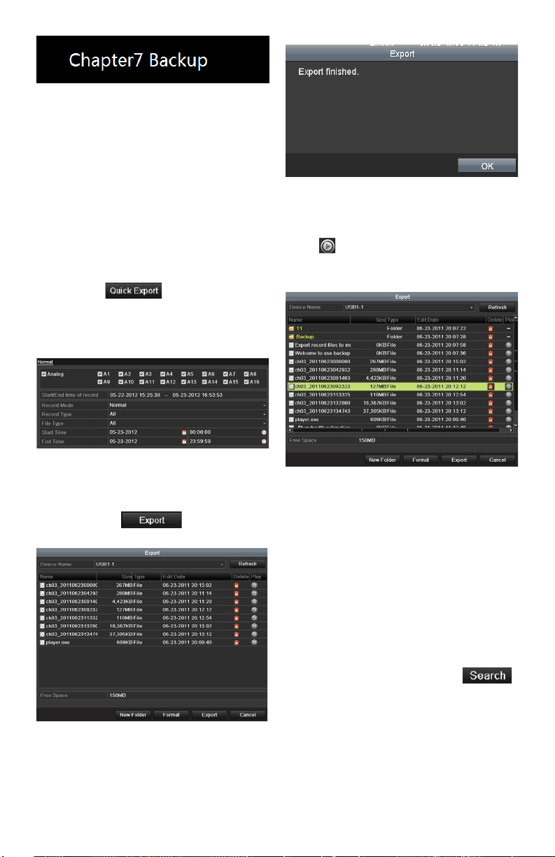
Backing Up Footage Files
Quick Export
Purpose:
Exportrecordlestobackupdevice(s)quickly.
Steps:
1. EnterVideoExportinterface.
Menu>Export>Normal
Choosethechannel(s)youwanttobackup
and click .
Note:Thetimedurationofrecordingson
aspeciedchannelcannotexceedoneday.
Otherwise,themessagebox“Max.24hours
areallowedforquickexport.”willpopup.
Video Export Interface
2. Export.
GotoExportinterface,choosebackup
device and click tostartexporting.
Note: Here we show a USB Flash Drive.
Quick Export using USB1-1
StayintheExportinterfaceuntilall
desiredlesareexported.
Export Finished
3. Check backup result.
ChoosetheleintheExportinterfaceand
click to check it.
Note: ThePlayer(player.exe)willbe
exportedautomatically.
Checkup of Quick Export Result Using USB1-1
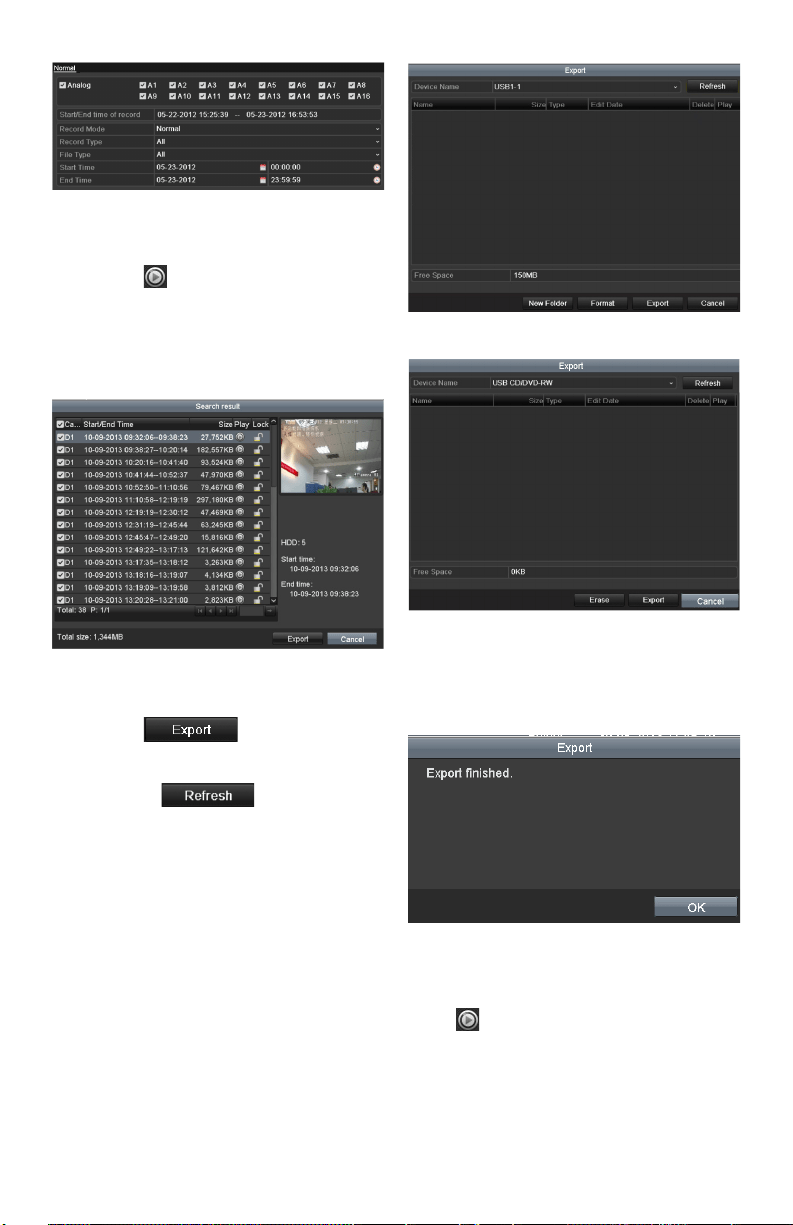
Backing up by Video Search
Purpose:
Filescanbestoredtovariousdevices,suchas
USBdevices(USBashdrives,USBHDDs,USB
writer)andDVD-R/W.
Backup using USB ash drives, USB HDDs,
USB writer and DVD-R/W
Steps:
1. EnterExportinterface.
Menu>Export>Normal
2. Set search condition and click .
Notes:
1) SixdierentRecordtypesare
selectable:Continuous,Motion,
Alarm,Motion&Alarm,Command
TriggeredandManual.
2) Twodierentletypesareselectable:
Unlocked and Locked.
www.LaViewSecurity.com 23
Normal Video Search for Backup
3. Selectthelesyouwanttobackup.
Click toplaytheleifyouwantto
check it.
Checkthecheckboxnexttothelesyou
want to back up.
Note: Thesizeofcurrentlyselectedlesis
displayedinthelower-leftcornerofthewindow.
Result of Normal Video Search for Backup
4. Export.
Click and start backup.
Note: If the inserted device is not
recognized:
• Click .
• Reconnect device.
• Check for compatibility from vendor.
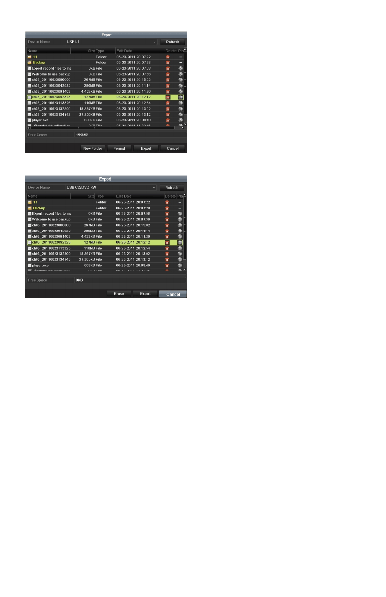
YoucanalsoformatUSBashdrives
or USB HDDs via the device. USB writer and
DVD-R/Wcannotbeformatted.
Export by Normal Video Search using USB Flash Drive
Export by Normal Video Search using USB Writer
StayintheExportinterfaceuntilalllesare
exported.Amessageboxsaying“Exportnished”
will signify the process is complete.
Export Finished
5. Check backup result.
ChoosetheleinExportinterfaceand
click to check it.
Note: ThePlayer(player.exe)willbe
exportedautomatically.
www.LaViewSecurity.com24
Checkup of Export Result using USB Flash Drive
Checkup of Export Result using USB Writer
www.LaViewSecurity.com 25
Conguring General
Network Settings
Purpose:
Network settings must be properly congured
before you operate DVR over network.
Steps:
1. Enter the Network Sengs interface.
Menu >Conguraon>Network
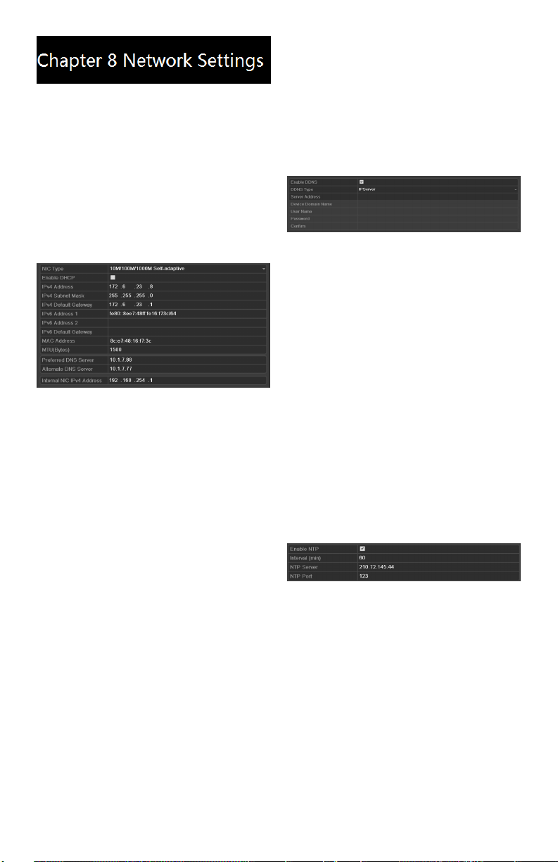
2. Select the General tab.
Network Settings Interface
3. In the General Settings interface,you
cancongurethefollowingsettings:NIC
Type,IPv4Address,IPv4Gateway,MTU
andDNSServer.
IftheDHCPserverisavailable,youcan
checkthecheckboxnexttoDHCP to
automatically obtain an IP address and
other network settings from that server.
4. Afterconguringthegeneralsettings,
click Apply to save the settings.
Conguring advanceed
Settings
Conguring DDNS
Purpose:
If your DVR is set to use PPPoE as its default
network connection, you may set Dynamic DNS
(DDNS)tobeusedfornetworkaccess.
Prior registration with your ISP is required before
conguringthesystemtouseDDNS.
Steps:
1. EntertheNetworkSettingsinterface.
Menu >Conguraon>Network
2. Select the DDNS tabtoentertheDDNS
Settings interface.
DDNS Settings Interface
3. Check the DDNS checkboxtoenablethis
feature.
4. Select DDNS Type.FivedierentDDNS
typesareselectable:IPServer,DynDNS,
PeanutHull,NO-IPandHiDDNS.
Conguring NTP Server
Purpose:
A Network Time Protocol (NTP) Server can be
conguredonyourDVRtoensuretheaccuracyof
systemdate/time.
Steps:
1. EntertheNetworkSettingsinterface.
Menu >Conguraon>Network
2. Select the NTP tabtoentertheNTP
Settings interface.
NTP Settings Interface
3. Check the Enable NTPcheckboxto
enable this feature.
4. CongurethefollowingNTPsettings:
• Interval: Timebetweenthetwo
synchronizingactionswithNTP
server.Theunitoftimeisin
minutes.
• NTP Server: IPaddressofNTP
server.
• NTP Port: PortofNTPserver.
5. Click the Apply button to save settings
andexittheinterface.
Note: The me synchronizaon interval can be
set from 1 to 10,080 min, and the default value is
www.LaViewSecurity.com26
60min. If the DVR is connected to a public network,
you should use a NTP server that has a me
synchronizaon funcon, such as the server at the
Naonal Time Center (IP Address: 210.72.145.44).
If the DVR is set up in a customized network, NTP
soware can be used to establish a NTP server
used for me synchronizaon.
Conguring RTSP
Purpose:
The RTSP (Real Time Streaming Protocol) is
a network control protocol designed for use in
entertainment and communications systems to
control streaming media servers.
Steps:
1. EntertheNetworkSettingsmenu
Menu >Conguraon>Network
2. Select the More Settings tab to enter the
More Settings menu
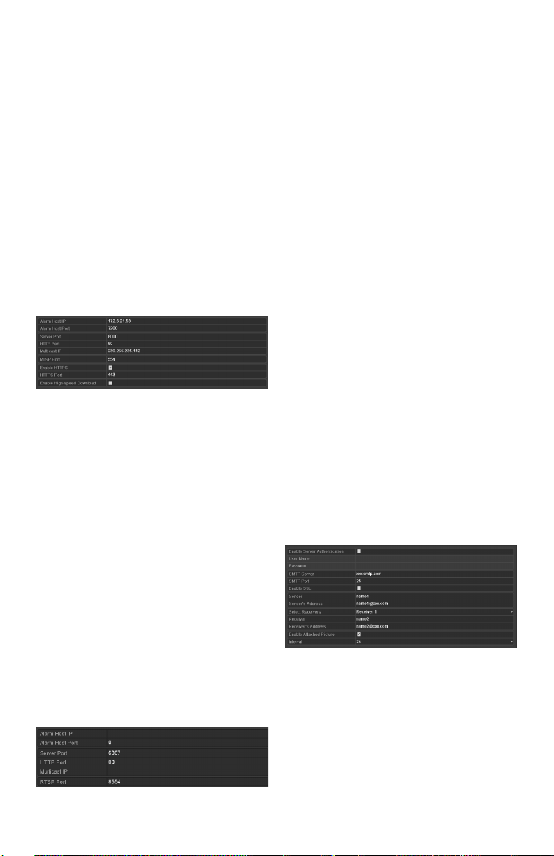
RTSP Settings Interface
3. EntertheRTSPportinthetexteld
nextto RTSP Service Port.Thedefault
RTSPportis554,andyoucanchangeit
accordingly.
4. Click Apply button to save settings and
exitthemenu.
Conguring Server and HTTP
Ports
Purpose:
Youcan change the server and HTTPports in the
NetworkSettingsmenu.The default server port is
8000andthedefaultHTTPportis80.
Steps:
1. EntertheNetworkSettingsinterface.
Menu>Conguration>Network
2. Select the More Settings tab to enter the
More Settings interface.
More Settings Interface
3. EntertheServerPortandHTTPPortin
thetextelds.ThedefaultServerPortis
8000andtheHTTPPortis80,andyou
canchangethemaccordingtodierent
requirements.
4. Click Apply button to save settigns and
exittheinterface.
Note: The Server Port should be set to the range of
2000-65535 and is used for remote client soware
access. The HTTP port is used for remote IE access.
Conguring Email
Purpose:
Thesystemcanbeconguredtosendanemail
noticationtodesignatedusersif,analarmmotion
event is detected or if the administrator password
is changed.
BeforeconguringtheemailSettings,theDVR
mustbeconnectedtoalocalareanetwork(LAN)
thatmaintainsanSMTPmailserver.Thenetwork
must also be connected to either an intranet or the
Internetdependingonthelocationofthee-mail
accountstowhichyouwanttosendnotications.
Steps:
1. EntertheNetworkSettingsinterface.
Menu>Conguration>Network
2. Set the IPv4 Address, IPv4 Subnet Mask,
IPv4GatewayandthePreferredDNSServer
intheNetworkSettingsmenu.
3. Click the Apply button to save the settings.
1. Select the Email tabtoentertheEmail
Settings interface.
Email Settings Interface
2. Congurethefollowingsettings:
Server Authentication (optional):
Checkthecheckboxtoenabletheserver
authentication feature.
User Name:Theuseraccountofsender’s
emailforSMTPserverauthentication.
Password:Thepasswordofsender’semail
forSMTPserverauthentication.
SMTP Server: TheSMTPServerIPaddress
www.LaViewSecurity.com 27
orhostname(e.g.,smtp.263xmail.com).
SMTP Port No.: TheSMTPport.The
defaultTCP/IPportusedforSMTPis25.
Enable SSL (optional):Clickthecheckbox
toenableSSLifrequiredbytheSMTP
server.
Sender: Thenameofsender.
Sender’s Address: Theemailaddressof
sender.
Receivers: Select the receiver. Up to 3
receiverscanbecongured.
Receiver: Thenameofusertobenotied.
Receiver’s Address:Theemailaddressof
usertobenotied.
Attached Pictures: Checkthecheckbox
nexttoEnable Attached Picture if you
want to send emails with attached alarm
sceneimages.Theintervalisthetimebefore
anotheralarmsceneimageissent.Youcan
alsosetSMTPportandenableSSLhere.
Interval:Theintervalreferstothetime
between two alam scene pictures.
E-mail Test: Sends a test message to verify
thattheSMTPservercanbereached.
3. Click the Apply button to save settings.
4. YoucanclickTest button to test whether
your settings work. An Attention message
boxwillpopup.Referto0.
Remote Viewing
Purpose:
You can view both the live and recorded footage
fromyourmobiledeviceslikesmartphones,tablets
or laptops.
Steps:
1.Connect the DVR to your router.
2.Find out the Local IP address of the
DVR in your Local Area Network (i.e.:
192.168.x.x,10.0.0.x)
3.Inyournetworkroutersettinginterface,
completethePortForwardingoftheHTTP
Port(Default:80),SERVERPort(Default:
8000)andRTSPPort (Default: 8554) for
the IP address of the DVR.
4.Download LaView Net / LaView Net
HD from the IOS App Store or Google
Play Store
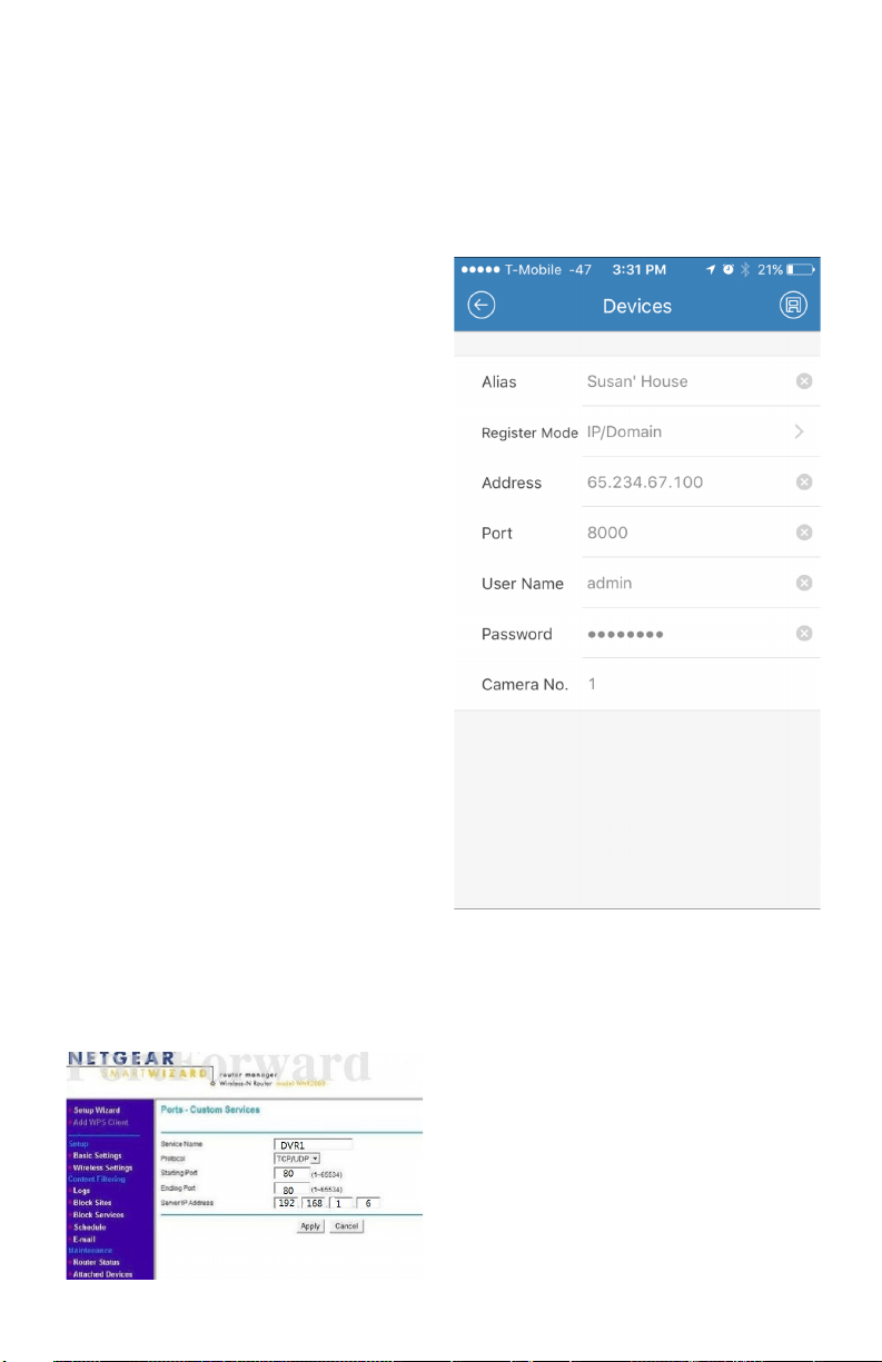
5.Set up the device in the app by going to
Menu > Devices > Add > Manual Adding.
Seegurebelowformoredetails
6.Save the setting and click on ‘Start Live
View’ to view the footage.
Alias:NameyourDVR
RegisterMode:IP/Domain
Address: Use Local IP address if your mobile device
is in the same LocalArea Network as your DVR.
Otherwise use Public IP address of your network
(Canbefoundatwww.canyouseeme.org).
Port:UseServerPort(Default:8000)
UserName:YourDVRLogincredentials(Default:
admin)
Password:YourDVRloginpassword
CameraNo.:Doesnotapply.Pleaseleaveitdefault.
www.LaViewSecurity.com28
Initializing HDDs
Purpose:
Anewlyinstalledharddiskdrive(HDD)mustbe
initialized before it can be used with your DVR.
Steps:
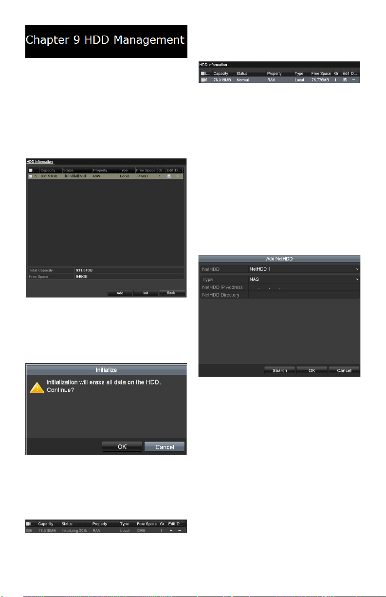
1. EntertheHDDInformationinterface.
Menu>HDD>General
HDD Information Interface
2. Select HDD to be initialized.
3. Click the Init button.
Confirm Initialization
4. Click the OK button to start
initialization.
Status Changes to Formatting
5. AftertheHDDhasbeeninitialized,the
status of the HDD will change from
Uninitialized to Normal.
HDD Status Changes to Normal
Note: Initializing the HDD will erase all data on it.
Managing Network HDD
Purpose:
YoucanaddtheallocatedNASordiskofIPSAN
toyourDVR,anduseitasanetworkHDD.
Steps:
1. EntertheHDDInformationinterface.
Menu>HDD>General
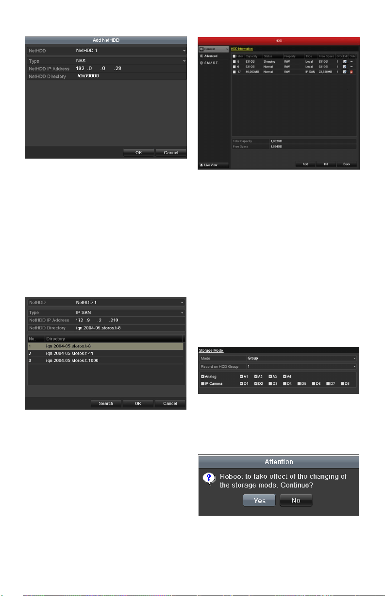
2. Click the Add button to enter the Add
NetHDDinterface.
HDD Information Interface
3. AddtheallocatedNetHDD.
4. SelectthetypeaseitherNASorIPSAN.
5. ConguretheNASorIPSANsettings.
• Add NAS disk:
1)EntertheNetHDDIPaddressinthe
texteld.
2)EntertheNetHDDDirectoryinthe
texteld.
3)Click the OK button to add the
conguredNASdisk.
Note: Upto8NASdiskscanbeadded.
www.LaViewSecurity.com 29
Add NAS Disk
• Add IP SAN:
1) EntertheNetHDDIPaddressin
thetexteld.
2) Click the Search button to view
availableIPSANdisks.
3) SelecttheIPSANdiskfromthe
list shown.
4) Click the OK button to add the
selectedIPSANdisk.
Note: Only1IPSANdiskcanbeadded.
AddIP SAN Disk
6. AftersuccessfullyaddingtheNASorIP
SANdisk,returntotheHDDInformation
menu.TheaddedNetHDDwillnowbe
displayed in the list.
Note: IftheaddedNetHDDis
uninitialized,pleaseselectitandclickthe
Init button for initialization.
Initialize Added NetHDD
Managing HDD Group
Setting HDD Groups
Purpose:
Multiple HDDs can be managed in groups. Video
fromspeciedchannelscanberecordedontoa
particular HDD group through HDD settings.
Steps:
1. EntertheStorageModeinterface.
Menu > HDD > Advanced
2. Set the ModetoGroup.
Storage Mode Interface
3. Click the Apply button and the following
messageboxwillpopup;
Attention for Reboot
4. Click the Yes button to reboot the device
and activate the changes.
www.LaViewSecurity.com30
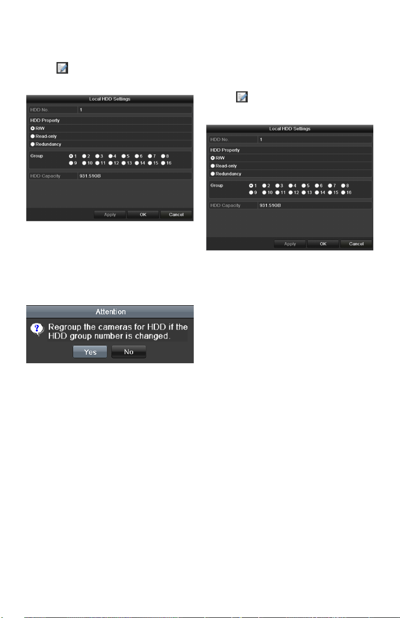
5. Afterrebootofdevice,entertheHDD
Information interface.
Menu>HDD>General
6. Select HDD from the list and click the
icon to enter the Local HDD Settings
interface.
Local HDD Settings Interface
7. SelecttheGroupnumberforthecurrent
HDD.
Note: ThedefaultgroupNo.foreachHDDis1.
8. Click the OKbuttontoconrmsettings.
Confirm HDD Group Settings
9. Inthepop-upmessagebox,clicktheYe s
buttontoconrmthesettings.
Setting HDD Property
Purpose:
TheHDDpropertycanbesettoredundancy,read-
onlyorread/write(R/W).BeforesettingtheHDD
property,pleasesetthestoragemodetoGroup
(refertosteps1-4ofChapterSettingHDDGroups
).
AHDDcanbesettoread-onlytoprevent
importantrecordedlesfrombeingoverwritten
when the HDD becomes full in overwrite recording
mode.
When the HDD property is set to redundancy, the
video can be recorded both onto the redundancy
HDD and the R/W HDD simultaneously so as to
ensure that reliability of video data is highly secured
and realiable.
Steps:
1. EntertheHDDInformationinterface.
Menu>HDD>General
2. Select HDD from the list and click the
icon to enter the Local HDD Settings
interface.
Set HDD Property
3. SettheHDDpropertytoR/W,Read-only
or Redundancy.
4. Click the OK button to save settings and
exittheinterface.
5. IntheHDDInformationmenu,theHDD
property will be displayed in the list.
Note: At least 2 hard disks must be installed on
yourDVR(andonemustbesettoR/Wproperty)if
you want to set a HDD to Redundancy.
www.LaViewSecurity.com 31
Conguring OSD Settings
Purpose:
You can congure the OSD (On-Screen Display)
settingsforthecamera,includingdate/time,camera
name,etc.
Steps:
1. EntertheOSDCongurationinterface.
Menu > Camera > OSD
2. SelectthecameratocongureOSD
settings.
3. EdittheCameraNameinthetexteld.
4. ConguretheDisplayName,Display
Date and Display Week by clicking the
checkbox.
5. SelecttheDateFormat,TimeFormatand
Display Mode.
6. Youcanusethemousetoclickanddrag
thetextframeonthepreviewwindowto
adjust the OSD position.
7. Click the Apply button to apply settings.
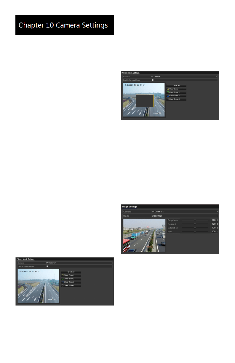
Conguring Privacy Mask
Purpose:
You can congure up to four privacy mask zones
which will prevent certain areas from being viewed
or recorded.
Steps:
1. EnterthePrivacyMaskSettingsinterface.
Menu > Camera >Privacy Mask
2. Select the camera to set a privacy mask
on.
3. CheckthecheckboxnexttoEnable
Privacy Mask to enable this feature.
Privacy Mask Settings Interface
4. Use the mouse to crop a zone on the
window.Dierentzoneswillbemarked
withdierentframecolors.
Note: Up to 4 privacy masks zones can be
conguredandthesizeofeachareacanbe
adjusted.
5. Thedesignatedprivacymaskzoneson
the window can be deleted by clicking
thecorrespondingClearZone1-4buttons
ontherightsideofthewindow,oryou
canclick Clear All to clear all zones.
Set Privacy Mask Area
6. Click the Apply button to save settings.
Conguring Video
Parameters
Steps:
1. EntertheImageSettingsinterface.
Menu > Camera >Image
Image Settings Interface
2. Select the camera to set image parameters
for.
3. Click the arrows to adjust each parameter.
Click the Apply button to save settings.
www.LaViewSecurity.com32
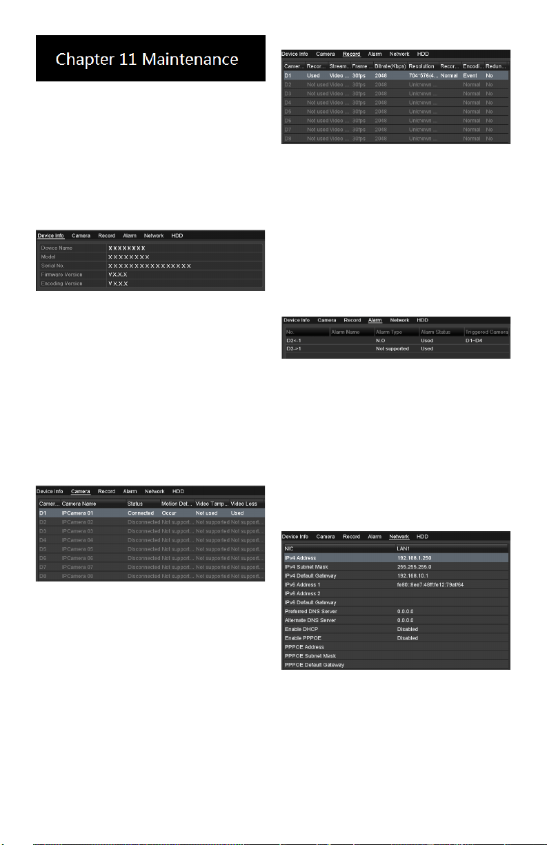
Viewing Device Information
Steps:
1. EntertheSystemInformationinterface.
Menu >Maintenance>System Info
2. Click the Device Info tab to see the
Device Information menu where you can
accessthedevicename,model,serialNo.
,rmwareversionandencodingversion.
Device Information Menu
Viewing Camera
Information
Steps:
1. EntertheSystemInformationinterface.
Menu >Maintenance>System Info
2. Click the Camera tab to see the Camera
Information menu where you can view the
status of each camera.
Camera Information Menu
Viewing Record Information
Steps:
1. EntertheSystemInformationinterface.
Menu >Maintenance>System Info
2. Click the Record tab to see the Record
Information menu where you can access
the recording status encoding parameters
of each camera.
Record Information Menu
Viewing Alarm Information
Steps:
1. EntertheSystemInformationinterface.
Menu >Maintenance>System Info
2. Click the Alarm tab to see the Alarm
Information menu where you can access
the alarm information.
Alarm Information Menu
Viewing Network Information
Steps:
1. EntertheSystemInformationinterface.
Menu >Maintenance>System Info
2. Click the NetworktabtoseetheNetwork
Information menu where you can view the
network information.
Network Information Menu
Viewing HDD Information
Steps:
1. EntertheSystemInformationinterface.
Menu >Maintenance>System Info
2. Click the HDD tab to see the HDD
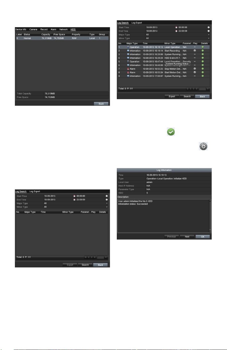
www.LaViewSecurity.com 33
Information menu where you can view the
HDDstatus,freespace,property,etc.,
HDD Information Menu
Searching & Export Log
Files
Purpose:
Theoperation,alarm,exceptionandother
information about the DVR can be stored in log
les,whichcanbeviewedandexportedatany
time.
Steps:
1. EntertheLogSearchinterface.
Menu >Maintenance>Log Search
Log Search Interface
2. Setthelogsearchconditionstorene
yoursearch:StartTime,EndTime,Major
TypeandMinorType.
3. Click the Searchbuttontondmatching
logles.
4. Thematchinglogleswillbedisplayed
on the list shown below.
Log Search Results
Note: Upto2000loglescanbedisplayedat
once.
5. Youcanclickthe button of each
log or double click it to view its detailed
information,youcanalsoclickthe
buttontoviewtherelatedvideolesif
available.
Log Details
6. Ifyouwishtoexportthelogles,click
the ExportbuttontoentertheExport
menu.

www.LaViewSecurity.com34
Export Log Files
7. Select the backup device from the
dropdown list under Device Name.
8. Click Export toexporttheloglestothe
selected backup device.
Youcanclickthe New Folder button to
createanewfolderinthebackupdevice,
or click the Format button to format the
backupdevicebeforelogexport.
Notes:
1) Please connect the backup device to DVR
beforeinitiatinglogexport.
2) Theloglesexportedtothebackupdevice
arenamedaccordingtoexportingtime,e.g.,
20110514124841logBack.txt.
To export all the log les:
YoucanentertheLogExportinterface.
Menu> Maintenance> Log Information> Log
Export
Log Export Interface
CheckthecheckboxnexttotheHDD,and
clicktheExportbuttontoexportallthe
loglesstoredintheHDD.
Upgrading System
Purpose:
The rmware on your DVR can be upgraded by
localbackupdeviceorremoteFTPserver.
Upgrading by Local Backup
Device
Steps:
1. Connect your DVR with a local backup
devicewheretheupdatermwareleis
located.
2. EntertheUpgradeinterface.
Menu >Maintenance>Upgrade
3. Click the Local Upgrade tab to enter the
local upgrade menu.
Local Upgrade Menu
4. Selecttheupdatermwarelefromthe
backup device.
5. Click the Upgrade button to start
upgrade.
6. Aftertheupgradingiscomplete,reboot
theDVRtoactivatethenewrmware.
Restoring Default Settings
Steps:
1. EntertheDefaultinterface.
Menu > Maintenance > Default
Restore Factory Default
2. Click the OK button to restore the default
settings.
Note: Besides network parameters (IP address,
subnet mask, gateway, MTU, default route and
server port), all other parameters of the device
will be restored to factory default sengs.
www.LaViewSecurity.com 35
Conguring General
Settings
Purpose:
Conguretheoutputresolution,systemtime,and
mousepointerspeed.Menu>Conguration>
Generalinterface.
Steps:
1. EntertheGeneralSettingsinterface.
Menu>Conguration>General
2. Select the General tab.
General Settings Interface
3. Congurethefollowingsettings:
• Language: Thedefaultlanguage
used is English.
• Resolution: Select the output
resolution,whichmustbethe
same as the resolution of the
monitor screen.
• Time Zone: Select the time zone.
• Date Format: Select the date
format.
• System Date: Select the system
date.
• System Time: Select the system
time.
• Mouse Pointer Speed: Set the
speed of the pointer; 4 levels are
congurable.
• Enable Wizard:Enable/disable
the Wizard to appear when the
device starts up.
• Enable ID Authentication:
Enable/disabletheuseofthe
login password.
4. Click the Apply button to save settings.
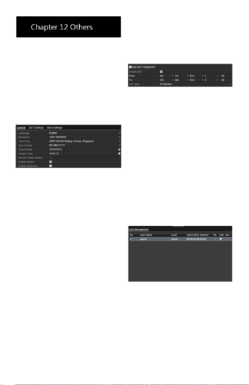
Conguring DST Settings
Steps:
1. EntertheGeneralSettingsinterface.
Menu>Conguration>General
2. Select the DST Settings tab.
DST Settings Interface
CheckthecheckboxnexttotheAutoDST
AdjustmentitemorchecktheEnableDST
checkbox,thenchoosethedateoftheDSTperiod.
Managing User Accounts
Purpose:
ThedefaultaccountintheDVRisAdministrator.
The user name is admin and the password is 12345.
TheAdministrator hasthepermissiontoadd/delete
usersandcongureuserparameters.
Adding a User
Steps:
1. EntertheUserManagementinterface.
Menu>Conguration>User
User Management Interface
2. Click the Add button to enter the Add
User menu.
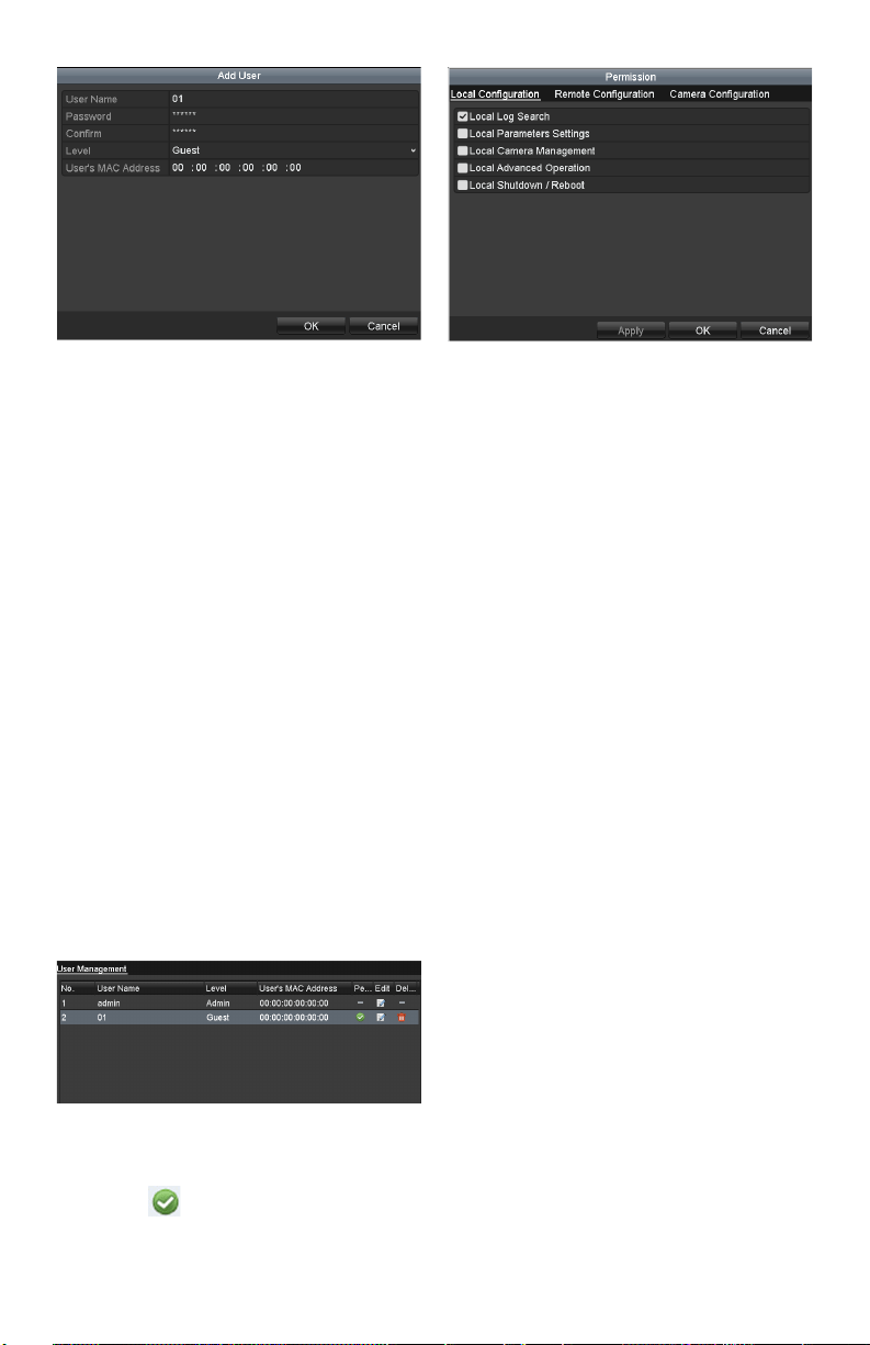
www.LaViewSecurity.com36
Add User Menu
3. Entertheinformationforanewuser:
UserName,Password,LevelandUser’s
MAC Address.
Level: Set the user level to Operator or
Guest.Dierentuserlevelshavedierent
operating permission.
• Operator: TheOperator user level
haspermissionforTwo-wayAudio
inRemoteCongurationandall
operating permission in Camera
Conguration.
• Guest: TheGuestuserdoesnot
havepermissionforTwo-wayAudio
inRemoteCongurationandhas
local/remoteplaybackinCamera
Conguration.
• User’s MAC Address: TheMAC
address of the remote PC which logs
ontotheDVR.Ifitisconguredand
enabled,itonlyallowstheremote
user with this MAC address to access
the DVR.
4. Click the OK button to save settings
and go back to the User Management
interface.Theaddednewuserwillbe
displayed on the list.
Added User Listed in User Management Interface
5. Select the user from the list and then click
the button to enter the Permission
Settings interface.
User Permission Settings Interface
6. Set the operating permissions (Local
Conguration,RemoteCongurationand
CameraConguration)fortheuser.
Local Conguration
• LocalLogSearch:Searching/viewing
logs and system information of DVR.
• Local Parameters Settings:
Conguringparameters,restoring
factory default parameters and
importing/exportingconguration
les.
• LocalCameraManagement:The
adding,deletingandeditingofIP
cameras.
• Local Advanced Operation: Operating
HDDmanagement(initializingHDD,
settingHDDproperty),upgrading
systemrmware,clearingI/Oalarm
output.
• Local Shutdown Reboot: Shutting
down or rebooting the DVR.
Remote Conguration
• Remote Log Search: Remotely
viewing logs that are saved on the
DVR.
• Remote Parameters Settings:
Remotelyconguringparameters,
restoring factory default parameters
andimporting/exportingconguration
les.
• Remote Camera Management:
Remoteadding,deletingandediting
of the IP cameras.
• Remote Serial Port Control:
ConguringsettingsforRS-232and
RS-485ports.
• Remote Video Output Control:
Remotely Sending button control
signals.
• Two-WayAudio:Realizingtwo-way
audio between the remote client and
the DVR.
www.LaViewSecurity.com 37
• Remote Alarm Control: Remotely
arming(notifyalarmandexception
messagetotheremoteclient)and
controlling the alarm output.
• Remote Advanced Operation:
Remotely operating HDD (initializing
HDD,settingHDDproperty),
upgradingsystemrmware,clearing
I/Oalarmoutput.
• RemoteShutdown/Reboot:Remotely
shutting down or rebooting the DVR.
Camera Conguration
• Remote Live View: Remotely
viewing live video from selected
camera(s).
• Local Manual Operation: Locally
starting/stoppingmanualrecording,
photo capturing and alarm output of
selectedcamera(s).
• Remote Manual Operation: Remotely
starting/stoppingmanualrecording,
photo capturing and alarm output of
selectedcamera(s).
• Local Playback: Locally playing back
recordedlesfromselectedcamera
(s).
• Remote Playback: Remotely playing
backrecordedlesfromselected
camera(s).
• LocalPTZControl:Locally
controllingPTZmovementof
selectedcamera(s).
• RemotePTZControl:Remotely
controllingPTZmovementof
selectedcamera(s).
• LocalVideoExport:Locally
exportingrecordedlesfromselected
camera(s).
7. Click the OK button to save settings and
exitinterface.
Note: Only the admin user account has the
permission to restore factory default parameters.
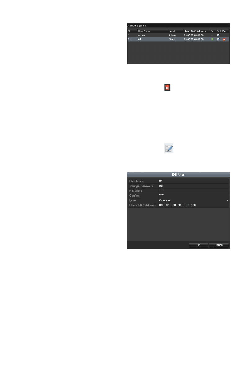
Deleting a User
Steps:
1. EntertheUserManagementinterface.
Menu>Conguration>User
2. Select the user to be deleted from the list.
User List
3. Click the icon to delete the selected
user.
Editing a User
Steps:
1. EntertheUserManagementinterface.
Menu>Conguration>User
2. Select the user to be edited from the list.
3. Click the icontoentertheEditUser
interface.
Note: Theadminusercanalsobeedited.
Edit User Interface
4. Edituserinformation:Username,
password,levelandMACaddress.
CheckthecheckboxChange Password
if you want to change the password of the
current user.
5. Click the OK button to save settings and
exitthemenu.

www.LaViewSecurity.com38
FAQ
No image displayed on the monitor after
starting up normally.
Possible Reasons
a) NoVGAorHDMIconnections.
b) Connection cable is damaged.
c) Input mode of the monitor is incorrect.
Steps
1. Verify the device is connected to the
monitorviaHDMIorVGAcable.
Ifnot,pleaseconnectthedevicewiththe
monitor and reboot.
2. Verify the connection cable is good.
If there is still no image display on the
monitorafterrebooting,pleasecheckifthe
connectioncableisgood,andchangeacable
to connect again.
3. Verify Input mode of the monitor is
correct.
Please check the input mode of the monitor
matches with the output mode of the device
(e.g. if the output mode of DVR is HDMI
output,thentheinputmodeofmonitor
mustbetheHDMIinput).Andifnot,please
modify the input mode of monitor.
4. Check if the fault is solved by the step 1
to step 3.
Ifitissolved,nishtheprocess.
Ifnot,pleasecontacttheengineertodothe
further process.
There is an audible warning sound “Di-Di-
Di-DiDi” after a new bought DVR starts up.
Possible Reasons
a) NoHDDisinstalledinthedevice.
b) TheinstalledHDDhasnotbeen
initialized.
c) TheinstalledHDDisnotcompatible
withtheDVRorisbroken-down.
Steps
1. Verify at least one HDD is installed in
the DVR.
1) Ifnot,pleaseinstallthecompatible
HDD.
Note: Pleaserefertothe“Quick
OperationGuide”fortheHDD
installation steps.
2) Ifyoudon’twanttoinstallaHDD,
select“Menu>Conguration>
Exceptions”,andunchecktheAudible
Warningcheckboxof“HDDError”.
2. Verify the HDD is initialized.
1) Select“Menu>HDD>General”.
2) If the status of the HDD is
“Uninitialized”,pleasecheckthe
checkboxofcorrespondingHDDand
clickthe“Init”button.
3. Verify the HDD is detected or is in good
condition.
1) Select“Menu>HDD>General”.
2) If the HDD is not detected or the
statusis“Abnormal”,pleasereplace
the dedicated HDD according to the
requirement.
4. Check if the fault is solved by the step
1 to step 3.
1) Ifitissolved,nishtheprocess.
2) Ifnot,pleasecontacttheengineertodo
the further process.
The status of the added IPC displays
as “Disconnected” when it is connected
through Private Protocol. Select
“Menu>Camera>Camera>IP Camera” to
get the camera status.
Possible Reasons
a) Networkfailure,andtheDVRandIPC
lost connections.
b) Theconguredparametersareincorrect
when adding the IPC.
c) Insucientbandwidth.
Steps
1. Verify the network is connected.

www.LaViewSecurity.com 39
1) ConnecttheDVRandPCwiththeRS-
232 cable.
2) OpentheSuperTerminalsoftware,and
executethepingcommand.Input“ping
IP”(e.g.ping172.6.22.131).
Note: Simultaneously press Ctrl and C
toexitthepingcommand.
Ifthereexistsreturninformationand
thetimevalueislittle,thenetworkis
normal.
2. Verifythecongurationparametersare
correct.
1) Select“Menu>Camera>Camera>IP
Camera”.
2) Verify the following parameters are the
same with those of the connected IP
devices,includingIPaddress,protocol,
managementport,usernameand
password.
3. Verify the whether the bandwidth is
enough.
1) Select“Menu>Maintenance>Net
Detect>NetworkStat.”.
2) Check the usage of the access
bandwidth,andseeifthetotal
bandwidth has reached its limit.
4. Check if the fault is solved by the step 1
to step 3.
Ifitissolved,nishtheprocess.
Ifnot,pleasecontacttheengineertodothe
further process.
The IPC frequently goes online and
oine and the status of it displays as
“Disconnected”.
Possible Reasons
a) TheIPCandtheDVRversionsarenot
compatible.
b) Unstable power supply of IPC.
c) Unstable network between IPC and
DVR.
d) Limitedowbytheswitchconnected
with IPC and DVR.
Steps
1. Verify the IPC and the DVR versions are
compatible.
1) EntertheIPCManagementinterface
“Menu>Camera>Camera>IP
Camera”,andviewthermwareversion
of connected IPC.
2) EntertheSystemInfointerface
“Menu>Maintenance>System
Info>DeviceInfo”,andviewthe
rmwareversionofDVR.
2. Verify power supply of IPC is stable.
1) Verify the power indicator is normal.
2) WhentheIPCisoine,pleasetrythe
ping command on PC to check if the PC
connects with the IPC.
3. Verify the network between IPC and DVR
is stable.
1) WhentheIPCisoine,connectPCand
DVRwiththeRS-232cable.
2) OpentheSuperTerminal,usetheping
command and keep sending large data
packagestotheconnectedIPC,and
checkifthereexistspacketloss.
Note: Simultaneously press Ctrl and C
toexitthepingcommand.
Example: Input ping 172.6.22.131 –l
1472 –f.
4. Verifytheswitchisnotowcontrol.
Checkthebrand,modeloftheswitch
connectingIPCandDVR,andcontactwith
the manufacturer of the switch to check if it
hasthefunctionofowcontrol.Ifso,please
turn it down.
5. Check if the fault is solved by the step 1
to step 4.
Ifitissolved,nishtheprocess.
Ifnot,pleasecontacttheengineertodothe
further process.
No monitor connected with the DVR locally
and when you manage the IPC to connect
with the device by web browser remotely,
of which the status displays as Connected.

www.LaViewSecurity.com40
And then you connect the device with the
monitor via VGA or HDMI interface and
reboot the device, there is black screen with
the mouse cursor.
Connect the DVR with the monitor before
startup via VGA or HDMI interface, and
manage the IPC to connect with the device
locally or remotely, the status of IPC
displays as Connect. And then connect the
device with the CVBS, and there is black
screen either.
Possible Reasons:
AfterconnectingtheIPCtotheDVR,theimage
is output via the main spot interface by default.
Steps:
1. Enabletheoutputchannel.
2. Select“Menu>Conguration>LiveView
>View”,andselectvideooutputinterfacein
thedrop-downlistandcongurethewindow
you want to view.
Notes:
1) Theviewsettingscanonlybe
conguredbythelocaloperationof
DVR.
2) Dierentcameraordersandwindow-
divisionmodescanbesetfordierent
outputinterfacesseparately,anddigits
like“D1”and“D2”standsforthe
channelnumber,and“X”meansthe
selected window has no image output.
3. Check if the fault is solved by the above
steps.
Ifitissolved,nishtheprocess.
Ifnot,pleasecontacttheengineertodothe
further process.
Live view stuck when video output locally.
Possible Reasons:
a) PoornetworkbetweenDVRandIPC,
andthereexistspacketlossduringthe
transmission.
b) Themotiondetectionandalarm
functionsareenabled,andthe
parametersofMainStream(Normal)
andMainStream(Event)aredierent.
So the image looks stuck due to the
imagechangesbetweendierent
resolutions.
c) Theframeratehasnotreachedthereal-
time frame rate.
Steps:
1. Verify the network between DVR and IPC
is connected.
1) Whenimageisstuck,connecttheRS-
232 ports on PC and the rear panel of
DVRwiththeRS-232cable.
2) OpentheSuperTerminal,andexecute
thecommandof“ping 192.168.0.0 –l
1472 –f” (the IP address may change
accordingtotherealcondition),and
checkifthereexistspacketloss.
Note: Simultaneously press Ctrl and C
toexitthepingcommand.
2. Check the parameters of Main Stream
(Normal)andMainStream(Event).
Select “Menu > Record > Parameters >
Record”, and set the resolution of Main
Stream (Event) the same as the one of Main
Stream(Normal).
3. Verifytheframerateisreal-timeframe
rate.
Select “Menu > Record > Parameters >
Record”,andsettheFrameratetoFullFrame.
4. Check if the fault is solved by the above
steps.
Ifitissolved,nishtheprocess.
If not, please contact the engineer to do the
further process.
Live view stuck when video output remotely
via the Internet Explorer or platform
software.
Possible Reasons:
a) PoornetworkbetweenDVRandIPC,
andthereexistspacketlossduringthe
transmission.
b) PoornetworkbetweenDVRandPC,
andthereexistspacketlossduringthe
transmission.
c) Theperformancesofhardwarearenot
goodenough,includingCPU,memory,
etc..
Steps:
1. Verify the network between DVR and IPC
is connected.
www.LaViewSecurity.com 41
1) Whenimageisstuck,connecttheRS-
232 ports on PC and the rear panel of
DVRwiththeRS-232cable.
2) OpentheSuperTerminal,andexecute
thecommandof“ping 192.168.0.0 –l
1472 –f” (the IP address may change
accordingtotherealcondition),and
checkifthereexistspacketloss.
Note: Simultaneously press Ctrl and C toexit the
ping command.
2. Verify the network between DVR and PC
is connected.
1) Open the cmd window in the Start
menu,oryoucanpress“windows+R”
shortcut key to open it.
2) Use the ping command to send large
packettotheDVR,executethe
commandof“ping192.168.0.0–l
1472–f”(theIPaddressmaychange
accordingtotherealcondition),and
checkifthereexistspacketloss.
Note: Simultaneously press Ctrl and C
toexitthepingcommand.
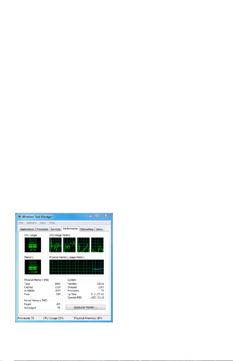
3. Verify the hardware of the PC is good
enough.
Simultaneously press Ctrl,Alt and Delete to
enterthewindowstaskmanagementinterface,
asshowninthefollowinggure.
Windows task management interface
Selectthe“Performance”tab;check
the status of the CPU and Memory.
Iftheresourceisnotenough,please
end some unnecessary processes.
4. Check if the fault is solved by the above
steps.
Ifitissolved,nishtheprocess.
If not, please contact the engineer to do the
further process.
When using the DVR to get the live view
audio, there is no sound or there is too much
noise, or the volume is too low.
Possible Reasons:
a) Cable between the pickup and IPC is not
connected well; impedance mismatches or
incompatible.
b) Thestreamtypeisnotsetas“Video&
Audio”.
c) Theencodingstandardisnotsupported
with DVR.
Steps:
1. Verify the cable between the pickup and
IPC is connected well; impedance matches
and compatible.
LogintheIPCdirectly,andturntheaudioon,
check if the sound is normal. If not, please
contact the manufacturer of the IPC.
2. Verify the setting parameters are correct.
Select “Menu > Record > Parameters >
Record”,andsettheStreamTypeas“Audio
&Video”.
3. Verify the audio encoding standard of the
IPC is supported by the DVR.
DVR supports G722.1 and G711 standards,
and if the encoding parameter of the input
audioisnotoneoftheprevioustwostandards,
youcanlogintheIPCtocongureittothe
supported standard.
4. Check if the fault is solved by the above
steps.
Ifitissolved,nishtheprocess.
Ifnot,pleasecontacttheengineertodothe
further process.
No record le found in the DVR local HDD,
and prompt “No record le found”.
Possible Reasons:
a) Thetimesettingofsystemisincorrect.

www.LaViewSecurity.com42
b) Thesearchconditionisincorrect.
c) TheHDDiserrorornotdetected.
Steps:
1. Verify the system time setting is correct.
Select “Menu > Conguration > General >
General”, and verify the “Device Time” is
correct.
2. Verify the search condition is correct.
Select“Playback”,andverifythechannel
and time are correct.
3. Verify the HDD status is normal.
Select“Menu>HDD>General”toviewthe
HDDstatus,andverifytheHDDisdetected
and can be read and written normally.
4. Check if the fault is solved by the above
steps.
Ifitissolved,nishtheprocess.
Ifnot,pleasecontacttheengineertodothe
further process.

www.LaViewSecurity.com 43