Loading ...
Loading ...
Loading ...
13
7. Electrical work
7.5. Wiring of main power supply and equipment capacity
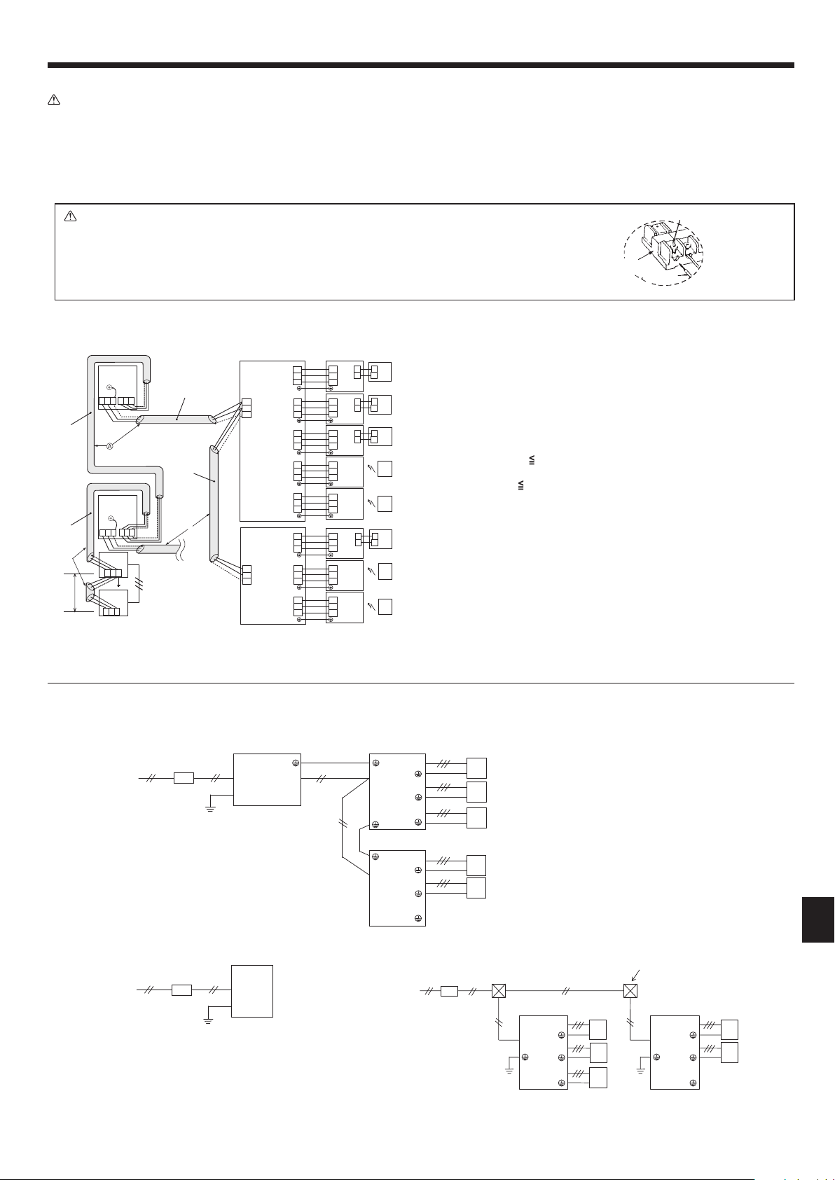
Schematic Drawing of Wiring (Example) (Fig. 7-3)
A Switch (Breakers for Wiring and Current Leakage)
B Outdoor Unit
C Branch Box
D A-Control indoor unit (M, P, S, series indoor unit)
E Pull Box
Fig. 7-3
TB7
TB3
(51)
L
3
L1
OC
TB7
(53)
OC
DC24V
Power Supply
Unit
System
controller
L
4
L5
M1 M2
S
M1 M2
S
S
M1 M2
S
TB3
M1 M2
S
M1 M2
S
M1 M2
TB3A
A-IC
(01)
A-IC
(02)
A-IC
(03)
A-IC
(04)
A-IC
MA-RC
MA-RC
MA-RC
WL-RC
(05)
A-IC
(06)
A-IC
(07)
A-IC
(08)
S1
S2
S3
TB
S1
S2
TB5/TB15
1
2
A
B
A
B
A
B
A
B
TB5/TB15
1
2
TB5/TB15
1
2
TB5/TB15
1
2
S3
TB
S1
S2
S3
TB
S1
S2
S3
TB
S1
S2
S3
TB
S1
S2
S3
TB
S1
S2
S3
TB
S1
S2
S3
TB
S1
S2
S3
TB3B
S1
S2
S3
TB3C
S1
S2
S3
TB3D
S1
S2
S3
TB3E
S1
S2
S3
TB3A
S1
S2
S3
TB3B
S1
S2
S3
TB3C
S1
S2
S3
M1
M2
S
TB5
M1
M2
S
TB5
L
(01)
(06)
2
Branch Box
A
A
Branch Box
WL-RC
MA-RC
WL-RC
WL-RC
Fig. 7-2
L1/L2
S1/S2/S3
S1/S2/S3
S1/S2/S3
L1/L2
S1/S2/S3
S1/S2/S3
S1/S2/S3
A
C
E
D
C
D
D
D
D
B1/B2
GR
S1/S2/S3
S1/S2/S3
S1/S2/S3
L1/L2
L1/L2
S1/S2/S3
S1/S2/S3
S1/S2/S3
L1/L2
D
D
D
D
D
C
C
B
A
208/230 VAC, 60 Hz
L1/L2
GR
A
B
<When Power Is Supplied Separately>
208/230 VAC, 60 Hz
208/230 VAC, 60 Hz
<When Power Is Supplied from the Outdoor Unit>
IMPORTANT
Make sure that the current leakage breaker is one compatible with higher
harmonics.
Always use a current leakage breaker that is compatible with higher harmon-
ics as this unit is equipped with an inverter.
The use of an inadequate breaker can cause the incorrect operation of inverter.
Longest length via outdoor units:
L
1
+ L
2
+ L
3
+ L
4
+ L
5
500 m (1640 ft.) (1.25 mm
2
[AWG 16] or more)
Longest transmission cable length
L
1
+ L
2
, L
3
+ L
4
, L
5
200 m (656 ft.) (1.25 mm
2
[AWG 16] or more)
A : Shielded wire
( ) : Address example
7.4. Branch box/outdoor wire connection and outdoor power supply cord connection (Fig. 7-2)
Warning:
• Be sure to attach the terminal block covers/panel of the outdoor unit securely. If it is not attached correctly, it could result in a re or an electric shock due to
dust, water, etc.
• Be sure to connect the power supply cords and the connecting wires for the indoor units, outdoor units, and branch boxes directly to the units (no intermediate
connections).
Intermediate connections can lead to communication errors if water enters the cords or wires and causes insufcient insulation to ground or a poor electrical
contact at the intermediate connection point.
(If an intermediate connection is necessary, be sure to take measures to prevent water from entering the cords and wires.)
Caution:
• Be careful not to make mis-wiring.
• Firmly tighten the terminal screws to prevent them from loosening.
• After tightening, pull the wires lightly to conrm that they not move.
• If the connecting wire is incorrectly connected to the terminal block, the unit does not operate normally.
• Connect wire from the branch box correctly to the terminal block.
• For future servicing, give extra length to connecting wire.
Terminal
block
Loosen terminal screw.
Lead wire
Connection details
RG79D595H06_EN.indd 13 9/7/2016 9:49:59 AM
Loading ...
Loading ...
Loading ...