INSTALLATION & USER GUIDE
IMPORTANT SAFETY INSTRUCTIONS
Carefully read the following Important information redarding installation
safety and maintenance. Keep these instruction for future reference.
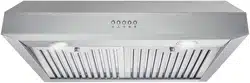
UNDER CABINET RANGE HOOD
COS-QB75 / QB90 INSTALL & USER MANUAL
QB SERIES
I N S P I R I N G T H E W O R L D ’ S K I T C H E N
2 3
THANK YOU FOR YOUR PURCHASE
Thank you for your purchase. We know that you have many brands and
products to choose from and we are honored to know that you have decided
to take one of our products into your home and hope that you enjoy it.
COSMO appliances are designed according to the strictest safety and performance
standard for the North American market. We follow the most advanced
manufacturing philosophy. Each appliance leaves the factory after thorough
quality inspection and testing. Our distributors and our service partners are
ready to answer any questions you may have regarding how to install, use and
care for your products. We hope that this manual will help you learn to use the
product in the safest and most effective manner .
If you have any questions or concerns, please contact the dealer from whom you
purchased it, or contact our Customer Support at:
1-888-784-3108.
TABLE OF CONTENTS
SAFETY INSTRUCTIONS 4
STAINLESS STEEL PERMANENT FILTERS 5
DIMENSIONS DIAGRAM: COS-QB75 6
DIMENSIONS DIAGRAM: COS-QB90 7
PARTS DIAGRAM 8
INSTALLATION REQUIREMENTS 9
PRE-INSTALLATION INSTRUCTIONS 10
INSTALLATION INSTRUCTIONS 11-12
RECIRCULATING FILTER INSTALLATION 13
OPERATING INSTRUCTIONS 14
MAINTENANCE 15
TROUBLESHOOTING 16
WARRANTY & SERVICE 18-19
4 5
IMPORTANT SAFETY INSTRUCTIONS
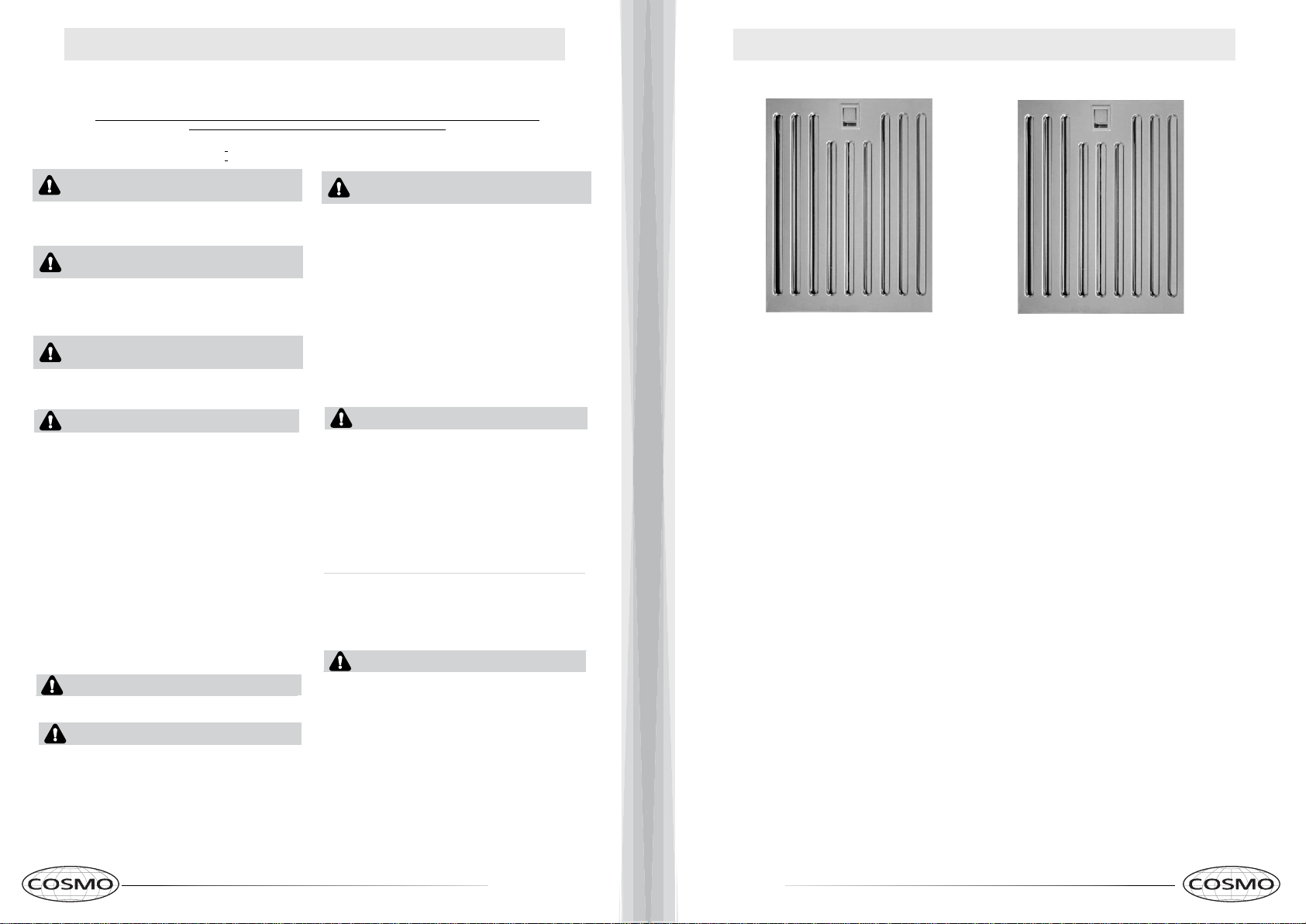
STAINLESS STEEL PERMANENT FILTERS
Read all instructions before using this appliance.
Save these instructions for future references
Approved for residential appliances. For residential use only .
Due to the weight and size of these vent hoods and to reduce the risk of personal injury or damage to the product,
TWO PEOPLE ARE REQUIRED FOR PROPER INSTALLATION.
IMPORTANT
SAFETY INSTRUCTIONS
CAUTION
FOR GENERAL VENTILATING USE ONLY. DO NOT USE
TO EXHAUST HAZARDOUS OR EXPLOSIVE MATERIALS
OR VAPORS.
WARNING
GROUNDING INSTRUCTIONS
This
appliance must be grounded. In the event of an electrical
short circuit, grounding reduces the risk of electric shock by
providing an escape wire for the electric current. This appliance
is equipped with a cord having a grounding wire with a grounding
plug. The plug must be plugged into an outlet that is properly
installed and grounded.
WARNING - IMPROPER GROUNDING CAN
RESULT IN A RISK OF ELECTRIC SHOCK.
Consult a qualified electrician if the grounding instructions are
not completely understood, or if doubt exists as to whether the
appliance is properly grounded.
Do not use an extension cord. If the power supply cord is too
short, have a qualified electrician install an outlet near the
appliance.
CAUTION
To reduce risk of fire and to properly exhaust air, do not
vent exhaust air into spaces within walls, ceilings, attics,
crawl spaces, or garages.
WARNING
TO REDUCE THE RISK OF FIRE, USE ONLY METAL
DUCT WORK. Install this hood in accordance with all
requirements specified.
WARNING
TO REDUCE THE RISK OF FIRE, ELECTRIC SHOCK, OR INJURY TO
PERSONS, OBSERVE THE FOLLOWING:
Use this unit only in the manner intended by the
manufacturer. If you have questions, contact the
manufacturer
B. Before servicing or cleaning the unit, switch power
off at service panel and lock service panel
disconnecting means to prevent
power from
being switched on accidentally. When the service disconnecting means
cannot be locked, securely fasten a prominent warning device, such as a
tag, to the service panel.
C. Installation Work and Electrical Wiring Must Be Done
By Qualied Person(s) In Accordance With all Aplicable Codes &
Standards, Including Fire-rated Construction.
exhausting of gases through the ue (Chimney) of fuel burning equipment to
prevent back- drafting. Follolow the heating equipment manufacturers
guideline and safety standards such as those published by the National Fire
Protection Association (NFPA), the American Society for Heating,
Refrigeration and Air Conditioning Engineers (ASHRAE), and the local code
authorities.
When cutting or drilling into wall or ceiling, do not
damage electrical wiring and other hidden utilities.
Ducted systems must always be vented to the outdoors.
A.
E.
F.
D. Sufcient air is needed for proper combustion and
WARNING
To
Reduce The Risk Of Fire Or Electric Shock, Do Not Use This Hood
With Any External Solid State Speed Control Device.
WARNING
WARNING
Unplug or disconnect the appliance
from the power supply
before servicing.
TO REDUCE THE RISK OF INJURY TO PERSONS, IN THE EVENT OF A
RANGE TOP GREASE FIRE, OBSERVE THE FOLLOWING:
A. SMOTHER FLAMES with a close-fitting lid, cookie sheet, or metal tray, then
turn off the burner. BE CAREFUL TO PREVENT BURNS. If the flames do not go
out immediately, EVACUATE AND CALL THE FIRE DEPARTMENT.
B. NEVER PICK UP A FLAMING PAN – You may be burned.
C. DO NOT USE WATER, including wet dishcloths or towels – a violent steam ex-
plosion will result.
D. Use an extinguisher ONLY if:
1
) You know you have a Class ABC extinguisher, and you already know how to
operate it.
2
) The fire is small and contained in the area where it started.
3) The fire department is being called.
4) You can fight the fire with your back to an exit.
Always leave safety grills and filters in place.Without these components,
operating blowers could catch onto hair, fingers and loose clothing.
The manufacturer declines all responsibility in the event of failure to observe
the instructions given here for installation,maintenance and suitable use of the
product. The manufacturer further declines all responsability for injury due to
negligence and the warranty of the unit automatically expires due to improper
maintenance.
WARNING
WARNING – TO REDUCE THE RISK OF A RANGE TOP GREASE FIRE:
A.
Never leave surface units unattended at high settings. Boilovers
cause smoking and greasy spillovers that may ignite. Heat oils slowly
on low or medium settings.
B. Always turn hood ON when cooking at high heat or when flaming food
(i.e. Crepes Suzette, Cherries Jubilee, Peppercorn Beef Flambe).
C. Clean ventilating fans frequently. Grease should not be allowed to ac-
cumulate on fan or filter.
D. Use proper pan size. Always use cookware appropriate for the size of
the surface element.
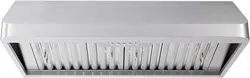
About Your New Filters
Stainless Steel Baffle Filters do not need linings or mesh inside of the filters and are
completely constructed out of stainless steel. The stainless steel construction allows
them to be used again after being cleaned or going through the dishwasher.
How do Baffle Filters Work?
They function by forcing the grease filled air to quickly and continuously change direction
as it passes through the filter. The grease is unable to change direction as fast as the air
carrying them, they end up getting caught on the metal blades and then trapped into the
filter tray.These filters are both efficient and require less maintenance.
6 7
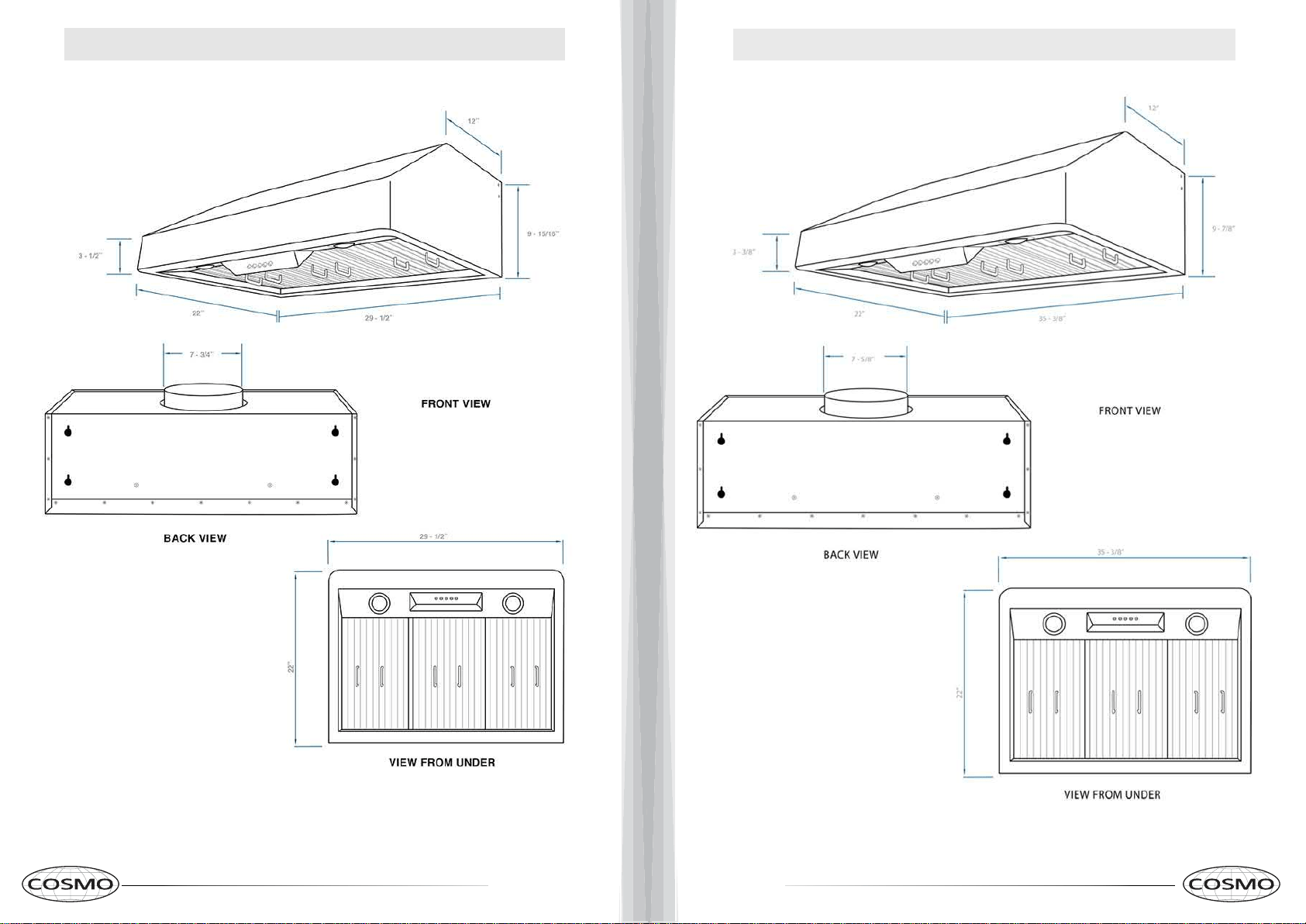
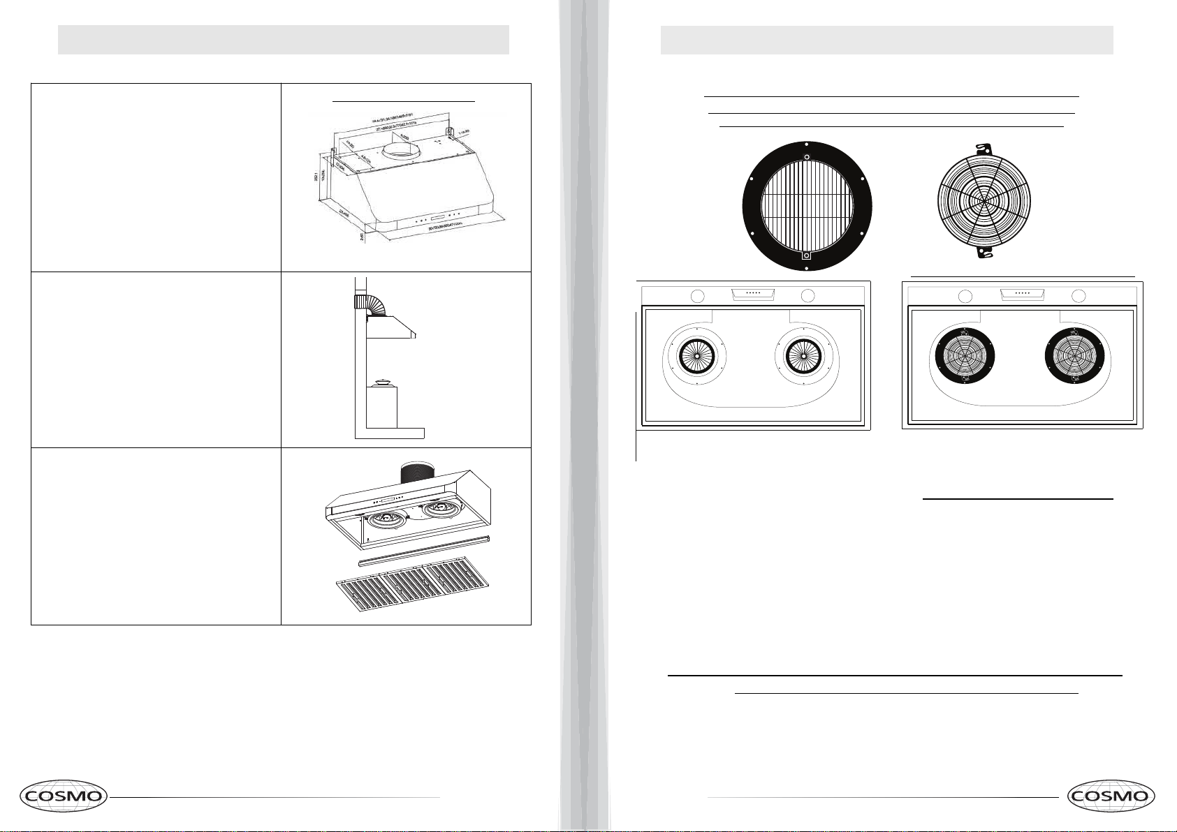
DIMENSIONS DIAGRAM: COS-QB75
DIMENSIONS DIAGRAM: COS-QB90
8 9
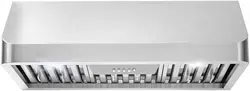
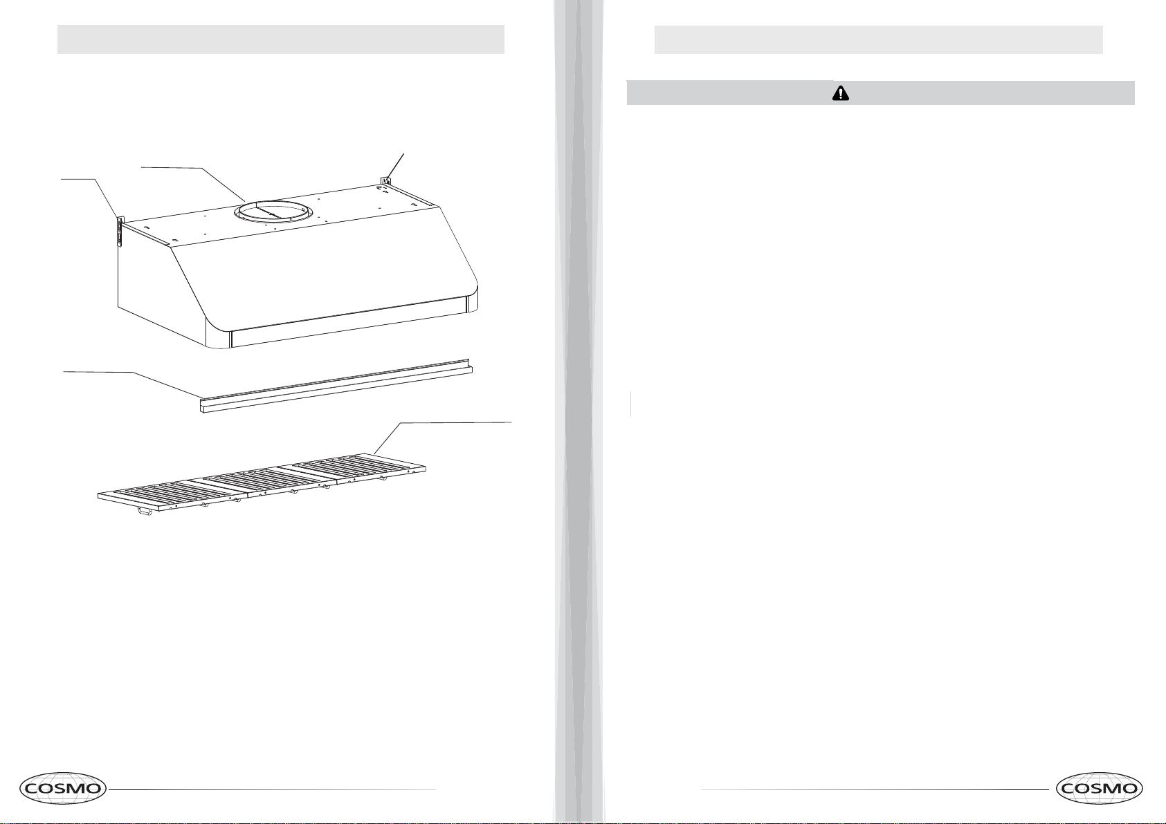
PARTS DIAGRAM
INSTALLATION REQUIREMENTS
MAIN PARTS
Baffle Filters
Damper
Mounting Bracket
Drip Tray
Mounting Bracket
Number of Filters will depend on Model /Size.
WARNING
Sufficient air is needed for proper combustion and exhausting of gases
through the chimney of fuel burning equipment to prevent back- drafting.
Follow the cooking equipment manufacturers guideline and safety stan-
dards such as those published by the National Fire Protection Association
(NFPA), the American Society for Heating, Refrigeration and Air Condi-
tioning Engineers (ASHRAE), and local code. When cutting or drilling into
wall or ceiling, do not damage electrical wiring and other hidden utilities.
Ducted systems must always be vented outdoors.
BEFORE YOU BEGIN
Read these instructions completely and carefully.
● IMPORTANT – Save these instructions for local inspector’s usage.
● Note to installer – Be sure to leave these instructions with the Con-
sumer.
● Note to Consumer – Keep these instructions for future reference.
● Skill Level – Installation of this vent hood requires basic mechani-
cal and electrical skills.
● Proper installation is the responsibility of the installer.
CAUTION:
Due to the weight and size of these vent hoods and to reduce the
risk of personal injury or damage to the product, TWO PEOPLE
ARE REQUIRED FOR PROPER INSTALLATION.
WARNING:
To reduce the risk of the fire or electrical shock, do not use this
range hood with any external solid-state speed control device.
Any such alteration from original factory wiring could result in
damage to the unit and/or create an electrical safety hazard. TO
REDUCE THE RISK OF THE FIRE, USE ONLY METAL
DUCTWORK. These vent hoods are designed to be installed
onto a wall or beneath a cabinet.
10 11
PRE-INSTALLATION REQUIREMENTS
INSTALLATION INSTRUCTIONS
DUCTWORK PLANNING
WALL FRAMING FOR ADEQUATE SUPPORT
IMPORTANT:
Plug the Unit in and Test all Functions Before Installing.
CAUTION: HOOD MAY HAVE VERY SHARP EDGES; PLEASE WEAR PROTECTIVE
GLOVES WHENEVER IT IS NECESSARY TO REMOVE ANY PARTS FOR INSTALLING,
CLEANING OR SERVICING.
• Please read the instructions carefully. Unpack the Range Hood and check
that all functions are working before installing.
• Ensure that the voltage (V) and the frequency (Hz) indicated on the sticker
match the voltage and frequency at the installation site.
• Check that the area behind the installation surface to be drilled is clear of any
electrical cables or pipes, etc.
• The stainless steel surfaces of the Range Hood are very easily damaged dur-
ing installation if scratched or bumped by tools. Please take care to protect the
surfaces during installation.
• Protect the cooktop surface below with cardboard, or the like, to prevent dam-
age occurring during installation.
• The manufacturer shall not be held liable for consumer’s failure to observe
and follow all pre-installation procedures and safety regulations.
• The vertical distance from the cooking surface to the bottom of the range
hood should be at least 24 in. to 36 in. for best performance.
• Determine if your installation will be top venting or back venting, and ensure
that the openings in the cabinet or wall are in the appropriate locations and ap-
propriate size.
• If this is a new installation, choose the venting method that suits your needs.
Cut out openings for the damper and for power access in the cabinet bottom or
exterior wall, depending on the installation method chosen.
•These vent hoods are equipped for 8" round ductwork. This hood may be
vented vertically through upper cabinet or ceiling. A duct transition piece is
supplied for vertical exhaust. You may use elbows (sold separately) to vent
horizontally through the rear wall.
•Determine the exact location of the vent hood.
•Plan the route for venting exhaust to the outdoors.
•Use the shortest and straightest duct route possible. For satisfactory per-
formance, duct run should not exceed 12.5 feet. equivalent length for any
duct configurations.
•Use metal ductwork only.
These vent hoods are heavy. Adequate structural support must be provided.
*Actual length of straight duct plus duct fitting must equivalent. Equivalent
lengths of duct pieces are based on actual tests conducted by Evaluation
Engineering and reflect requirements for good venting performance with any
ventilation hood.
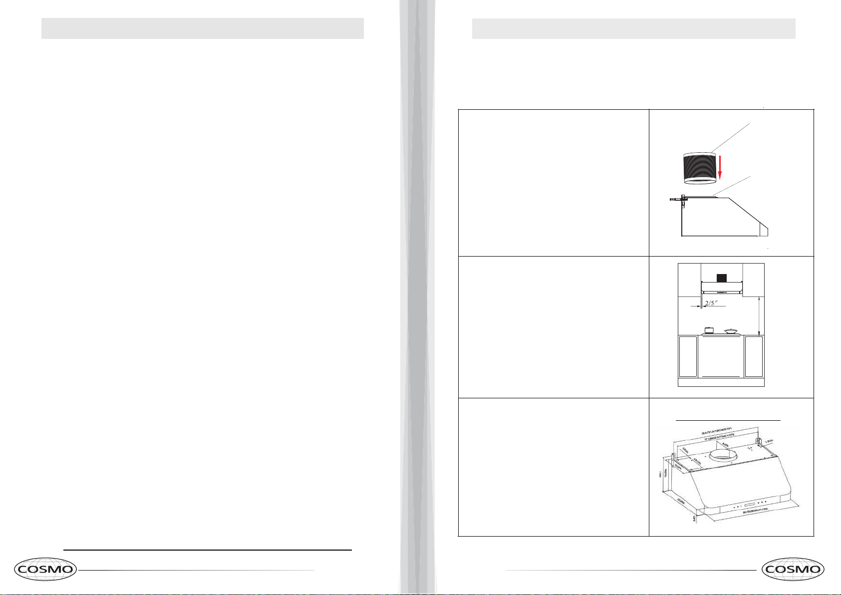
Step 2:
Clearance above stovetop
ranging from 24” to 36” is rec
ommended for optimal perfor
mance.
Please measure accordingly
before mounting this unit.
24" to 36"
Top Mounted Installation
A. Find the key holes at the top of the range hood.
Mark their locations at the installation location (Bottom
of Cabinet) with a pencil or marker.
B. Drill 5/16" (8mm) hole at each of the
marked
locations.
C.
Insert anchors into each drilled hole. Firmly
screw
them into place.
D. Hang your Range Hood into place by aligning the
anchors with the four holes in the top of the range
hood. Push in to place to lock into place
Step 1:
Connect the duct into the
damper.
Duct
Damper
Larger images on Pages 6-7
12 13
INSTALLATION INSTRUCTIONS
RECIRCULATING FILTER INSTALLATION
Step 3:
Connect installed duct to existing
ductwork. For best performance
avoid steep angles in duct work.
Step 4:
A. Install the Drip Tray inside the bottom
rear of the range hood.
B. Install the baffle filters by inserting at an
angle towards the rear of the range hood.
Push the filter up and insert front of filter
into front recess. Slightly lower the filter
then slide back until it is in proper position.
Rear Mounted Installation
A. Find the key holes in the back of the range hood.
Mark their locations at the installation location with a
pencil or marker.
B. Drill 5/16"
(8mm) hole at each of the marked
locations.
C. Insert anchors into each drilled hole. Firmly
screw them into place.
D. Hang your Range Hood into place by aligning the
anchors with the key holes in the back of the range
hood.
Larger images on Pages 6-7
Installing Recirculating Filters (For Ductless Model Only)
Skip this page if you are installing a Ducted Range Hood.
Charcoal Filters are only included with Ductless Models
B
efore installing m
ake sure the unit is powered off and unplugged.
Additional Aluminum or Baffle Filters can be purchased from
www.cosmoappliances.com
1. Remove the Baffle Filters from the Range Hood
2. Locate Fig. 1 , unscrew the 6 screws along the Motor Ring (metal circle).
Set motor ring to the side.
3. Take your Filter Ring and align the holes on the motor ring to the holes of the filter ring.
4. Screw the Filter Ring into motor ring.
5. Take the C
arbon Filter and lock into the Filter Ring by aligning the two tabs and twisting.
6. Repeat Steps 1-5 on the other side.
7. Reattach the Baffle Filters.
The carbon filter must be replaced every 4-6 months depending on use.
Figure 1
Motor Ring
Filter Ring
Carbon Filter
Motor Housing
Note: This is a top venting unit and a hole must be cut into the cabinet for proper installation.
AFTER CARBON FILTER INSTALLATION
14 15
OPERATING INSTRUCTIONS
MAINTENANCE
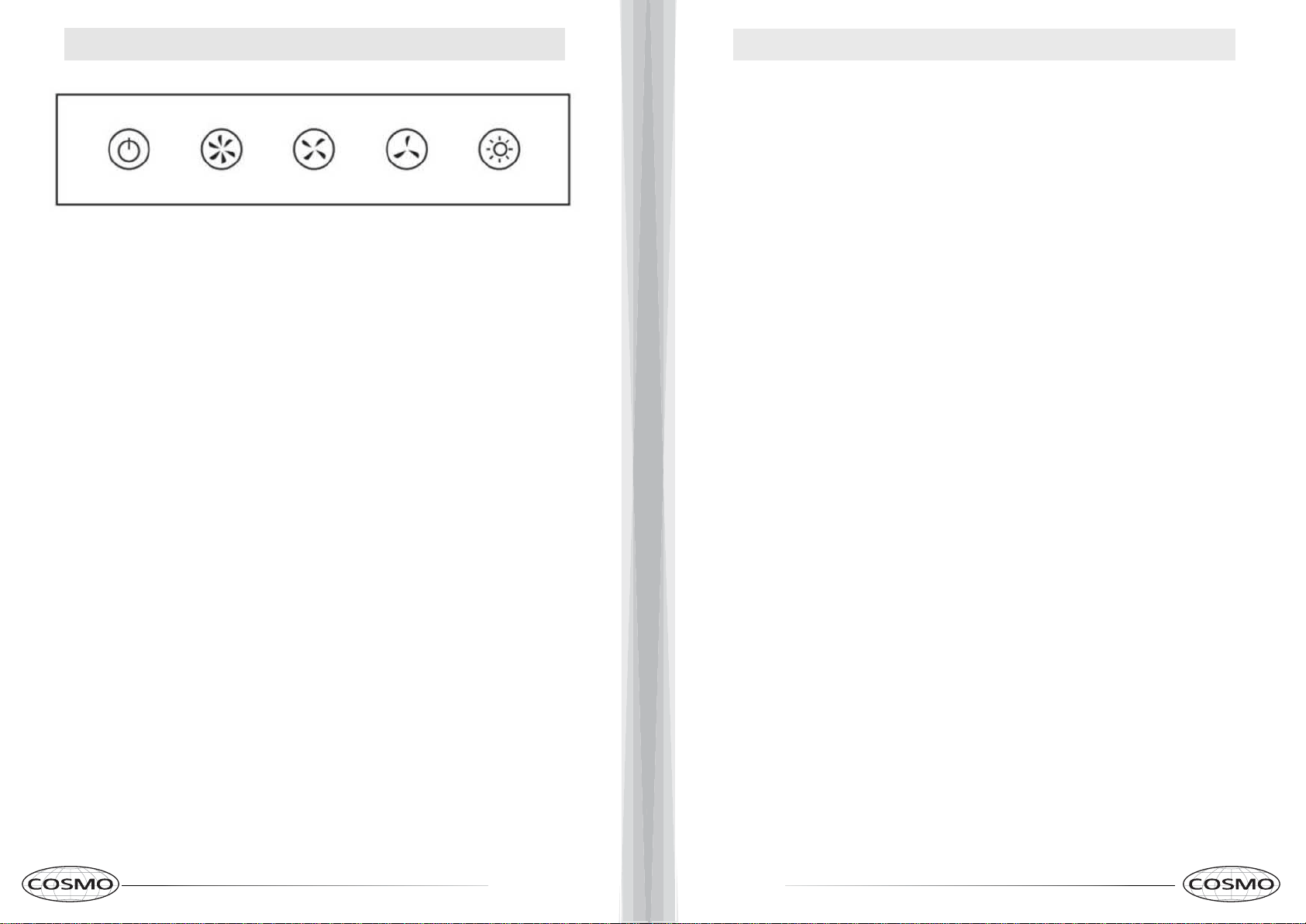
A. Power Button - Turn on/off the range hood
B. High Speed. - Press to turn fan on high speed.
C. Medium Speed - Press to turn fan on medium speed.
D
. Low Speed - Press to turn fan on low speed.
E. Light - Press to turn on light.
Push Button Controls
A
B
C D E
CAUTION: NEVER PUT YOUR HAND INSIDE OF THE UNIT WHILE ITS OPERATING.
FOR THE BEST PERFORMANCE CLEAN YOUR RANGE HOOD REGULARLY.
CLEANING
1. Use only mild soap or cleaning solutions to clean the range hoods
outer surface. Dry surfaces using a soft cloth.
2. Stainless Steel cleaner may be used on the external surface.
3. Cleaning the Baffle Filters: For daily cleaning, use hot, soapy
water and a soft cloth. Wipe dry and finish with a damp micro-fiber
cloth. Baffle filters can also be cleaned in the dishwasher.
4. Clean the Range Hood assembly once every 6 months.
5. DO NOT clean the motor or electrical components with water or any
other liquid
REPLACING LIGHT BULBS
CAUTION: LAMP UNIT MAY BE HOT! WAIT UNTIL THE UNIT IS COOL. BEFORE
ATTEMPTING TO REPLACE THE LIGHT BULBS MAKE SURE THE UNIT IS POWERED OFF AND
UNPLUGGED.
Note: Bulb Size GU10.
1. Remove the baffle filters
2. Reach behind the bulb, twist counter clockwise and push the bulb out of the panel.
3. Plug in new bulb and twist clockwise to lock into place.
5. Reinstall the baffle filters.
16 17
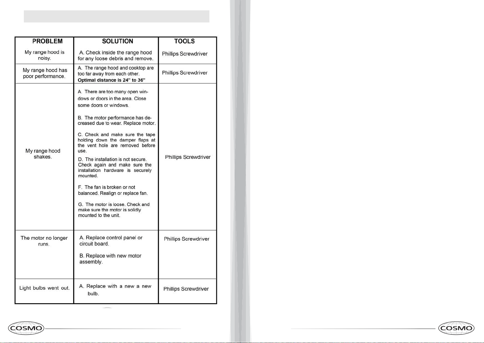
TROUBLESHOOTING
18 19
WARRANTY AND SERVICE
For full warranty details on this product please visit:
http://www.cosmoappliances.com/warranty
TO RECEIVE WARRANTY SERVICE, YOUR
PRODUCT MUST BE REGISTERED. TO REGISTER, VISIT:
WWW.COSMOAPPLIANCES.COM/WARRANTY
Correct Disposal of this product:
This marking indicates that this appliance should not
be disposed with other household wastes. To prevent
possible harm to the environment or human health
from uncontrolled waste disposal, recycle it responsibly to
promote the sustainable reuse of material resources.
IMPORTANT
Do Not Return This Product To The Store If
you have a problem with this product, please contact
Cosmo Customer Support at
+1(888)784-3108
DATED PROOF OF PURCHASE, MODEL #, AND SERIAL #
REQUIRED FOR WARRANTY SERVICE
IMPORTANT
Ne pas Réexpédier ce Produit au Magasin
Pour tout problème concernant ce produit, veuillez contacter
le service des consommateurs Cosmo Customer Support au
+1(888) 784-3108
UNE PREUVE D’ACHAT DATEE EST REQUISE POUR BENEFICIER DE
LA GARANTIE.
IMPORTANTE
No regrese este producto a la tienda
Si tiene algún problema con este producto, por favor contacte el
AYUDA AL CLIENTE COSMO al
+1(888)784-3108
(Válido solo en E.U.A).
NECESITA UNA PRUEBA DE DE COMPRA FECHADA, NÚMERO DE
MODELO Y DE SERIE PARA EL SERVICIO DE LA GARANTÍA
SCAN TO REGISTER
Electronic version of this manual is available at:
www.cosmoappliances.com
Cosmo is constantly making efforts to improve the quality and
performance of our products, so we may make changes to our
appliances without updating this manual.