INSTRUCTION MANUAL Battery Charger
PREPARING TO CHARGE
- 1. Be sure area around battery is well ventilated while battery is being charged.
- 2. Remove battery completely from boat/airplane or any confined area before charging.
- 3. If it is necessary to remove battery from a vehicle to charge, or to clean terminals, always remove the grounded terminal from the battery first. Make sure all accessories in the vehicle are turned off, so as not to cause an electrical arc.
- 4. Clean the battery terminals, taking care to avoid getting corrosive material in your eyes.
- 5. Add distilled water in each cell until battery acid reaches level specified by battery manufacturer. This helps purge excessive gas from cells. Do not overfill. For a battery without cell caps (maintenance free), carefully follow manufacturer’s charging instructions.
- 6. Study all battery manufacturer’s specific precautions, such as removing or not removing cell caps while charging, and recommended rates of charge.
- 7. Determine the voltage of the battery to be charged by referring to the vehicle manual. This unit is for charging a 12 volt battery only
Charger Location
- Locate charger as far away from battery as cables permit.
- Never place charger directly above battery being charged; gases from battery will corrode and damage charger.
- Never allow battery acid to drip on charger when reading gravity or filling battery.
- Never operate charger in a closed-in area or restrict ventilation in any way.
- Marine batteries must be removed and charged on shore.
- Do not set a battery on top of charger.
Connection Precautions
- Connect and disconnect the battery clamps only after unplugging the AC cord from the electric outlet.
- Never allow clamps to touch each other.
- Attach clamps to battery and chassis as indicated in “Battery Installed in Vehicle” steps 5 and 6, or in “Battery Outside of Vehicle” steps 2 to 5.
Follow these steps when the battery is installed in a vehicle
WARNING: A spark near the battery may cause an explosion. To reduce risk of a spark near the battery:
- Position AC and clamp cords to reduce risk of damage by hood, door, or moving engine part.
- Stay clear of fan blades, belts, pulleys, and other parts that can cause injury to persons.
- Check polarity of battery posts. POSITIVE (POS, P, +) battery post usually has larger diameter than NEGATIVE (NEG, N, –) post.
- Determine which post of battery is grounded (connected) to the chassis. If negative post is grounded to chassis (as in most vehicles), see 5. If positive post is grounded to the chassis, see 6.
- For negative-grounded vehicle, connect POSITIVE (RED) clamp from battery charger to POSITIVE (POS, P, ungrounded post of battery. Connect NEGATIVE (BLACK) clamp to vehicle chassis or engine block away from battery. Do not connect clip to carburetor, fuel lines, or sheet-metal body parts. Connect to heavy gauge metal part of the frame or engine block.
- For positive-grounded vehicle, connect NEGATIVE (BLACK) clamp from battery charger to NEGATIVE (NEG, N, –) ungrounded post of battery. Connect POSITIVE (RED) clamp to vehicle chassis or engine block away from battery. Do not connect clip to carburetor, fuel lines or sheet-metal body parts. Connect to a heavy gauge metal part of the frame or engine block.
- When disconnecting charger, disconnect AC cord, remove clamp from vehicle chassis, and then remove clamp from battery terminal.
- Do not charge the battery while the engine is operating.
- See operating instructions for length of charge information.
Follow these steps when the battery has been removed from a vehicle
WARNING: A spark near the battery may cause an explosion. To reduce risk of a spark near the battery:
- Check polarity of battery posts. The POSITIVE post (marked POS,P, +) usually has a larger diameter than the NEGATIVE battery post (marked NEG, N, –).
- Attach a 24-inch (minimum length) AWG #6 insulated battery cable to the NEGATIVE battery post (marked NEG, N, –).
- Connect the POSITIVE (RED) charger clamp to the POSITIVE battery post (marked POS, P, + or red).
- Stand as far back from the battery as possible, and do not face battery when making final connection.
- Carefully connect the NEGATIVE (BLACK) charger clamp to the free end of the battery cable connected to the NEGATIVE terminal.
- When disconnecting charger, always do so in reverse sequence of connecting procedure and break first connection while as far away from battery as practical.
Note: A marine (boat) battery must be removed and charged on shore. To charge it on board requires equipment specifically designed for marine use. This unit is NOT designed for such use.
- Check unit periodically for wear and tear. Return to manufacturer for replacement of worn or defective parts immediately.
- Read and Understand This Instruction Manual Before Using This Unit.
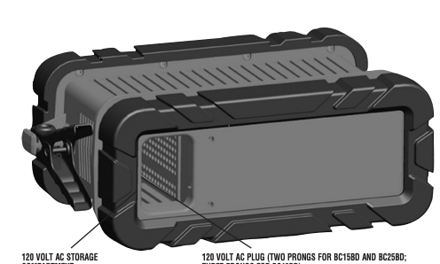
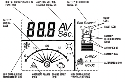
FEATURES
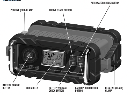
LCD Display Detail
OPERATING INSTRUCTIONS
Charging the Battery
WARNING: TO REDUCE THE RISK OF INJURY OR PROPERTY DAMAGE:
- Always disconnect the AC plug from the AC outlet first before disconnecting the charger from the battery to be charged.
- Ensure that all installation, operating instructions and safety precautions are understood and always carefully followed by the steps outlined in the “IMPORTANT SAFETY INSTRUCTION” section at the front of this manual.
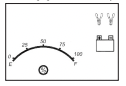
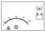
1. Plug the battery charger’s power cord into an AC outlet. The LCD screen will display the following (the clamp icon will flash, the empty battery icon and the gage without the pointer will light):
2. The charger’s battery clamps are color-coded. Red is positive; black is negative. Connect the battery clamps correctly to the corresponding connectors on the battery posts following the steps outlined in the “IMPORTANT SAFETY INSTRUCTION” section at the front of this manual.
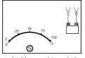
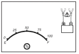
Notes: If the clamps are correctly connected with regard to polarity and the unit is properly connected to the AC outlet, the unit will be in Standby mode and the LCD screen will display the following (the clamp icons, arrow icons, the battery icon and the gage without the pointer light solid):
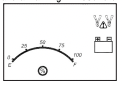
If the clamps are INCORRECTLY connected with regard to polarity, the LCD screen will display the following (the “+” and “–” inside the battery icon and the fault icon will flash and the clamp icons, the battery icon and the gage without the pointer will light) and a warning will sound until the clamps are disconnected:
Unplug the charger; then remove the clamps. Reconnect the clamps properly.
3. When the unit is properly connected, press the battery charge button on the control panel. The LCD screen will display the following:
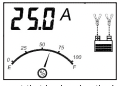
The digital display shows the output current that is charging the battery. The gauge indicates the charge status of the battery. The clamp icons and the battery icon light solid, the bars on the battery icon will change from empty to solid (bottom to top) repeatedly and the arrow icons will gradually and repeatedly move downward to the battery icon.
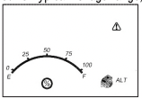
Notes: The icon will appear at the top right of the gauge section if the surrounding ambient temperature is higher than approximate 40°C. The “
  ” icon will appear at the top left of the gauge section if the surrounding ambient temperature is lower than 0°C. This is not a fault code, but indicates that the unit’s temperature compensation feature is operating. The charging process will start automatically approximately one minute after the unit is properly connected.
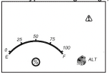
IMPORTANT: If the unit is overheated, the LCD screen will display the following (the overheat alarm icon, fault icon and the battery icon will flash; and the clamp icons, arrow icons and the gage without the pointer will light)
Disconnect the charger and allow the charger to cool for several minutes. Make sure there is adequate ventilation around the unit before attempting to charge again.
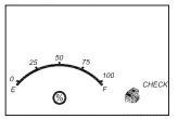
IMPORTANT: The charger will automatically detect the battery condition. If it detects a problem with the battery, the LCD screen will display the following (the fault icon and the battery icon will flash; and the clamp icons, arrow icons and the gage without the pointer will light):
Disconnect the charger. Have the battery checked by a qualified technician.
IMPORTANT: If the battery is not fully charged (the battery charge gauge does not reach 100%) after 18 hours of continuous charging, the battery may have internal damage and will not accept a charge. After 18 hours, the charging process will automatically cut-off, the LCD screen will display the following (the digital readout shows “F04”, the clamp icons, arrow icons, battery icon and the gage without the pointer will light solid):
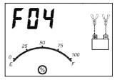
Disconnect the charger. Have the battery checked by a qualified technician.
4. When the battery is completely charged, the unit automatically goes into float charge mode and the LCD screen displays the following:
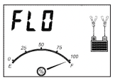
The digital display shows “FLO” to indicate that the unit is in float charge mode. The battery charge gauge points to 100%, indicating a full charge. The clamp icon and battery icon with four bars light solid, and the arrow icons will gradually and repeatedly move downward to the battery icon. In this mode, the unit monitors the battery voltage and charges as necessary to assure the battery maintains full capacity. The unit remains in float charge mode as long as the charger is connected to the battery and plugged into a functioning AC outlet.
When disconnecting charger, disconnect the AC cord, remove clamp from vehicle chassis, and then remove clamp from battery terminal.
Checking the Battery Voltage
TO CHECK THE BATTERY VOLTAGE IN STANDBY MODE
- Set up the battery charger and connect to the battery following steps 1 through 2 in the “Charging the Battery” section.
- Press the battery voltage check button. The LCD screen will display the following:
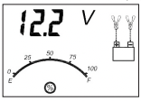
The digital display shows the current voltage of the connected battery for 10 seconds. During this period, pressing the battery voltage check button again will return the unit to standby mode. The gage without the pointer will light solid. The unit will automatically return to standby mode after 10 seconds.
TO CHECK THE BATTERY VOLTAGE IN CHARGING MODE:
Press the battery voltage check button and the LCD screen will display the following:
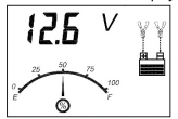
The digital display shows the current voltage of the connected battery for 10 seconds. During this period, pressing the battery voltage check button again will return the unit to charging mode. Pressing the alternator check button or the battery recondition button will have no effect. The unit will automatically return to charging mode after 10 seconds
When disconnecting charger, disconnect AC cord, remove clamp from vehicle chassis, and then remove clamp from battery terminal.
Using the Alternator Check Function
Set up the battery charger and connect to the battery following steps 1 through 2 in the “Charging the Battery” section.
PART 1
No Load (turn OFF all vehicle’s accessories): The battery must be fully charged before testing the alternator. Run the engine long enough to achieve normal idle speed and verify there is a no-load voltage.
- Press the alternator check button to start the check. The LCD screen will display the following to indicate the unit is analyzing the alternator:
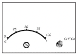
“Check” will flash, and the alternator icon and the gage without the pointer will light solid.
2. If the unit detects that the alternator is good, the LCD screen will display the following:
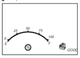
“Good”, the alternator icon and the gage without the pointer will light solid.
3. If the unit detects that the alternator is out of typical voltage range, the LCD screen will display the following:
The fault icon will flash; and the alternator icon, “ALT” and the gage without the pointer will light solid.
4. Press the alternator check button again to stop the test.
PART 2
Under Load (accessories ON): Next, load the alternator by turning on as many accessories as possible (except for A/C and Defrost).
1. Press the alternator check button to start the check. The LCD screen will display the following to indicate the unit is analyzing the alternator:
“Check” will flash, and the alternator icon and the gage without the pointer will light solid.
2. If the unit detects that the alternator is good, the LCD screen will display the following:
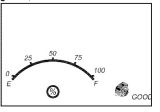
“Good”, the alternator icon and the gage without the pointer will light solid.
3. If the unit detects that the alternator is out of typical voltage range, the LCD screen will display the following:
The fault icon will flash; and the alternator icon, “ALT” and the gage without the pointer will light solid.
4. Press the alternator check button again to stop the test.
Notes: All buttons except the alternator check button are disabled in alternator check mode. The unit may detect that the alternator is out of typical voltage range because someone has added a number of accessory loads on the charging system, thereby increasing current demand from the alternator. MAKE SURE THAT THE ALTERNATOR IS RATED TO SUPPORT THE APPLICATION. This check may not be accurate for every make, manufacturer and model of vehicle. Check only 12 volt systems
When disconnecting the charger, disconnect AC cord, remove clamp from vehicle chassis, and then remove clamp from battery terminal.
Reconditioning the Battery
Periodic reconditioning is recommended to maintain a battery’s optimum performance. Battery recondition sends a series of electrical pulses to break up the crystalline form of lead sulfate and turn these chemicals into useful battery electrolytes. The process will stop automatically after 24 hours. To stop the process sooner, press the battery recondition button a second time. More than 24 hours may be needed to restore performance on some batteries. If so, repeat the process.
- 1. Set up the battery charger and connect to the battery following steps 1 through 2 in the “Charging the Battery” section.
- 2. Press the battery recondition button. The LCD screen will display the following:
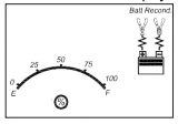
The battery recondition indicator, the clamp icons, the battery icon and the gage without the pointer will light solid, the bars on the battery icon will change from solid to empty (top to bottom) repeatedly and the battery recondition icons will flash.
- 3. To stop the reconditioning process, press the battery recondition button again. Pressing any other button during this process will have no effect.
IMPORTANT: If 5 cycles of reconditioning does not improve battery performance, discontinue and recycle the battery. The battery charger will go into charging mode after 24 hours automatically.
When disconnecting charger, disconnect AC cord, remove clamp from vehicle chassis, and then remove clamp from battery terminal.
Using the Engine Start Function
- 1. Set up the battery charger and connect to the battery following steps 1 through 2 in the “Charging the Battery” section.
- 2. Press the engine start button. The LCD screen will display the following*:
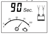
The digital display shows the countdown.* The battery charge gauge will indicate the battery’s current charge status. The engine start icon, clamp icons and battery icon light solid, and the bars on the battery icon will change from empty to solid (bottom to top) repeatedly and the arrow icons will gradually and repeatedly move downward to the battery icon. *The countdown will commence from “90” to “0”.
- 3. When “00” is reached, a beep will sound, engine start icon
 will begin flashing. The vehicle is ready to start.
- 4. Crank the engine using manufacturer’s guidelines, typically in 3 to 5 second bursts. The digital display shows “5 sec.” indicating a 5-second countdown.
- 5. After cranking, the unit will automatically adjust the charging current to 2A for 5 minutes and then revert to charging mode. To stop charging, press the charge button.
IMPORTANT: The function requires a resting/cooling period between attempts. Wait 4 to 5 minutes before a second attempt at starting the engine, if needed. When disconnecting charger, disconnect AC cord, remove clamp from vehicle chassis, and then remove clamp from battery terminal.
TROUBLESHOOTING
Unit Not Charging
- Make sure all connections are secure.
- Check that the charger is properly connected to a live 120 volt AC outlet.
- If the battery to be charged has fallen below 2 volts, the battery cannot be recharged with these chargers.
CARE AND MAINTENANCE
Storage
- Store the unit in a clean, dry, cool place when not in use.
- Clean the unit casing and cords (as necessary) with a dry (or slightly damp) cloth. Ensure that unit is completely disconnected from battery and power source before cleaning.
- To maintain the operating condition and maximize the life of the charger cords, always coil them loosely for storage. Do not wrap them around the unit or crimp them with a tight band.
ACCESSORIES
Recommended accessories for use with this unit may be available from the manufacturer. If you need assistance regarding accessories, please contact the manufacturer at 1-877-571-2391.
WARNING: The use of any accessory not recommended for use with this appliance could be hazardous.