Loading ...
Loading ...
Loading ...
Installation
14
15
Tab.3-4: suggested RCD parameter
Suggested max power input
Number of
inverter(s)/parallel Suggested RCD parameter(mA)
1
2
3
......
n
≥50×1
≥50×2
≥50×3
......
≥50×n
No load can be directly connected to the output side of the inverter.
Installation
-Each string of solar panels in series should be of same type and specification.
-Open Circuit Voltage of each string should not exceed 1000VDC
-The two string of same MPP tracker should have same number of solar panels.
Take Model.TP20KTL as example, the panel power of each MPP tracker should
not exceed 11kw, the total power of inverter should not exceed 22kw.
Recommended Voltage/Current for AC Breaker is 400V/60V.
If the inverter is equipped with “AC Breaker including the RCD”, the parameter
of the RCD refers to the following:
Danger
Warning
3.6 Electrical connection
After the inverter is correctly installed on the wall or support, the next step is the
electrical connection for the inverter. Electrical connection must be performed
according to related safety standards.
A misoperation electrical connection may cause personal injury or
death or damage the inverter irreversibly. Wiring operation must be
performed by a qualified electrical engineer.
All electrical installation must be complying with local and national
electrical standards.
Warning
Warning
The inverter cannot be connected to the grid unless approved
by the local electrical authority and all electrical connections
are completed by a qualified electrical engineer.
Please use cables of specification recommended by us,
or the system safety may be deraded.
The electrical connection for an inverter covers electrical cable connection and
communication cable connection.
3.6.1 Electric and electrical system structure
The electric and electrical connection for the whole solar energy power
generation system is shown as below:
Fig.3-10
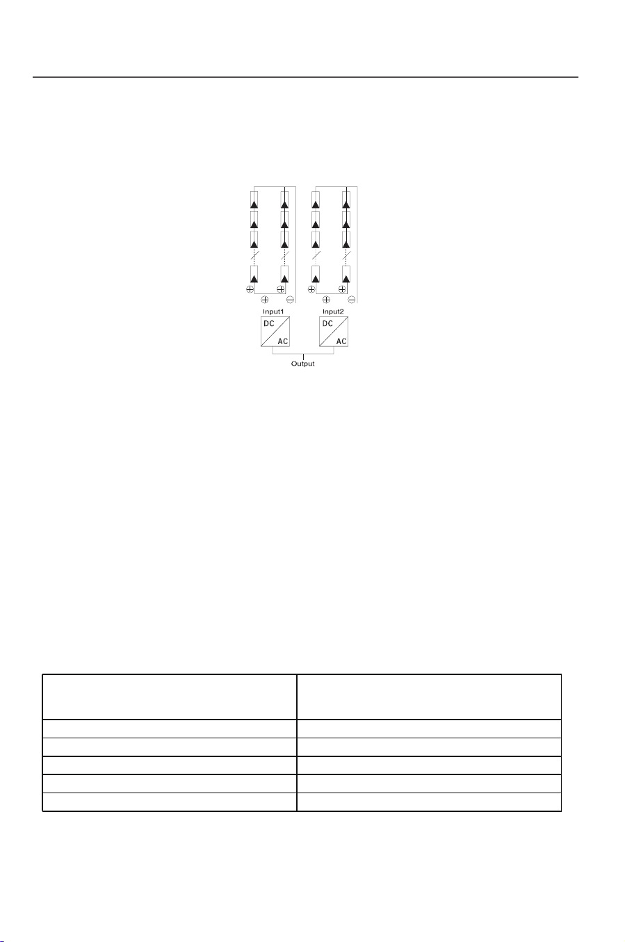
There are two independent MPP trackers in inverter, each MPP tracker has two
pairs of DC input terminals. The connection type refers to Fig.3-11. Keep DCt:
switch in an “OFF” state and make sure that:
Fig.3-11
Loading ...
Loading ...
Loading ...