Loading ...
Loading ...
Loading ...
10
*5
3
/4"
(146 mm)
1
1
/2"
(38 mm)
3/8" NPT dryer gas pipe
GAS SUPPLY CONNECTION REQUIREMENTS
■ Use an elbow and a 3/8" are x 3/8" NPT adapter tting
between the exible gas connector and the dryer gas
pipe, as needed to avoid kinking.
■ Use only pipe-joint compound. Do not use TEFLON
®
tape.
■ This dryer must be connected to the gas supply line with a
listed exible gas connector that complies with the standard
for connectors for gas appliances, ANSI Z21.24 or CSA 6.10.
BURNER INPUT REQUIREMENTS
Elevations above 2,000 ft. (610 m):
■ When installed above 2,000 ft. (610 m) a 4% reduction of the
burner Btu rating shown on the model/serial number plate is
required for each 1,000 ft. (305 m) increase in elevation.
Gas supply pressure testing
■ The dryer must be disconnected from the gas supply
piping system during pressure testing at pressures greater
than 1/2 psi.
DRYER GAS PIPE
■ The gas pipe that comes out through the rear of your dryer has
a 3/8" male pipe thread.
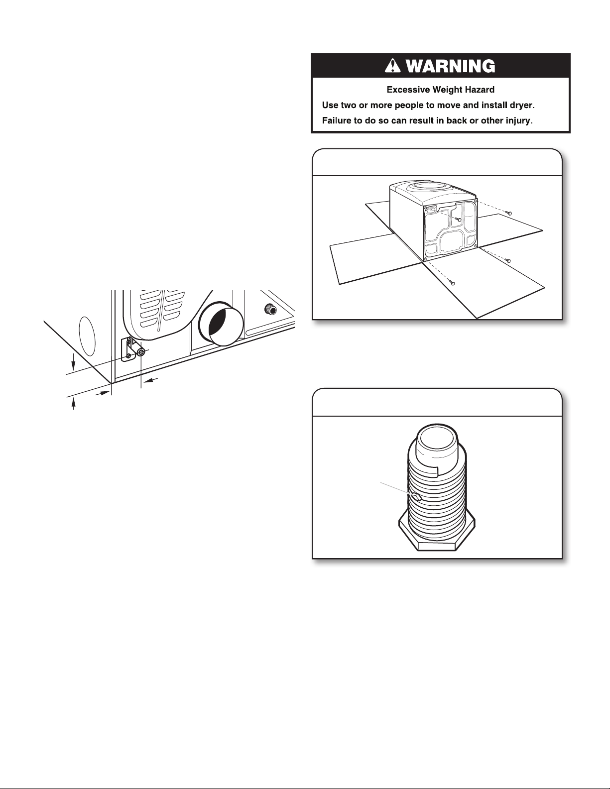
INSTALL LEVELING LEGS
To avoid damaging oor, use a large at piece of cardboard
from dryer carton; place under entire back edge of dryer.
Firmly grasp dryer body (not console panel) and gently lay
dryer down on cardboard.
Examine leveling legs and locate the diamond marking.
Screw legs into leg holes by hand – use a wrench to nish
turning legs until diamond marking is no longer visible.
Place a carton corner post from dryer packaging under each
of the two dryer back corners. Stand the dryer up. Slide the
dryer on the corner posts until it is close to its nal location.
Leave enough room to connect the exhaust vent.
1. Prepare dryer for leveling legs
2. Screw in leveling legs
diamond
marking
* NOTE: If the dryer is mounted on a pedestal, the gas
pipe height must be an additional 10" (254 mm) or
15.5" (394 mm) from the oor, depending on the pedestal
model. For a garage installation, the gas pipe height must
be an additional 18" (460 mm) from the oor.
Diamond
marking
Loading ...
Loading ...
Loading ...