1
INTRODUCTION
T
hank you for choosing BRK Brands, Inc. for your Smoke and Carbon
Monoxide Alarm needs. You have purchased a state-of-the-art Smoke &
C
O Alarm designed to provide you with early warning of a fire or Carbon
M
onoxide.
K
ey features include:
S
moke & Carbon Monoxide Combination Alarm.
O
ne alarm protects
a
gainst two deadly household threats.
I
ntelligent Sensing Technology
d
esigned to help reduce unwanted or
nuisance alarms.
Smart Interconnect can be interconnected to BRK Smoke Alarms.
O
ne interconnect wire carries both smoke and CO alarm signals.
S
ingle Button Test/Silence
e
liminates confusion. Depending on what
m
ode the alarm is in, pushing the button provides different functions
such as testing the alarm, silencing the alarm, re-testing the alarm
w
hen in silence and clearing the Latching feature.
L
atching Alarm Indicator
e
asily identifies initiating alarm even after the
a
larm condition has subsided.
Perfect Mount System includes a gasketless base for easy installation
a
nd a new mounting bracket that keeps the alarm secure over a wide
r
otation range to allow for perfect alignment.
D
ust Cover
i
s included to keep the alarm clean during construction.
E
asy Installation/Maintenance
f
eatures include a large opening in
the mounting bracket for easy access to wiring. A battery pull tab that
k
eeps the battery fresh until the home is occupied. A Side Load Battery
D
rawer allows for easy battery replacement without removing the alarm
from the ceiling or wall.
Improved UV Resistance keeps the alarm from discoloring over time.
A
ll BRK
®
a
nd
F
irst Alert
®
S
moke Alarms conform to regulatory
requirements, including UL217 and are designed to detect particles
of combustion. Smoke particles of varying number and size are
produced in all fires.
I
onization technology is generally more sensitive than photo-
electric technology at detecting small particles, which tend to be
p
roduced in greater amounts by flaming fires, which consume
c
ombustible materials rapidly and spread quickly.
Sources of these
fires may include paper burning in a wastebasket, or a grease fire in
the kitchen.
Photoelectric technology is generally more sensitive than ionization
technology at detecting large particles, which tend to be produced
in greater amounts by smoldering fires, which may smolder for
hours before bursting into flame. Sources of these fires may include
cigarettes burning in couches or bedding.
For maximum protection, use both types of Smoke Alarms on
each level and in every bedroom of your home.
USER’S MANUAL
Smoke & Carbon
Monoxide Alarm
AACC PPoowweerreedd SSmmookkee &&
CCaarrbboonn MMoonnooxxiiddee AAllaarrmm
wwiitthh BBaatttteerryy BBaacckk--uupp,,
SSiilleennccee FFeeaattuurree aanndd
LLaattcchhiinngg AAllaarrmm
Model SC9120B
I
nput: 120V AC
~
6
0 Hz, 0.09A
I
I
M
M
P
P
O
O
R
R
T
T
A
A
N
N
T
T
!
!
P
P
L
L
E
E
A
A
S
S
E
E
R
R
E
E
A
A
D
D
C
C
A
A
R
R
E
E
F
F
U
U
L
L
L
L
Y
Y
A
A
N
N
D
D
S
S
A
A
V
V
E
E
This user’s manual contains important information about your Alarm’s
operation. If you are installing the Alarm for use by others, you must leave
this manual — or a copy of it — with the end user.
Model
S
C9120B
P
rinted in Mexico
M08-0094-006
K1 08/08
TABLE OF CONTENTS
Introduction . . . . . . . . . . . . . . . . . . . . . . . . . . . . . . . . . . . . . . . . . . . . . . .1
Fire Safety Tips . . . . . . . . . . . . . . . . . . . . . . . . . . . . . . . . . . . . . . . . . .1-2
Installation . . . . . . . . . . . . . . . . . . . . . . . . . . . . . . . . . . . . . . . . . . . . .2-4
Where To Install This Alarm . . . . . . . . . . . . . . . . . . . . . . . . . . . . . . . .2
Where This Alarm Should Not Be Installed . . . . . . . . . . . . . . . . . . . .2
Before You Begin Installation . . . . . . . . . . . . . . . . . . . . . . . . . . . . . . .3
How To Install This Smoke/CO Alarm . . . . . . . . . . . . . . . . . . . . . .3-4
Using the Optional Locking Features . . . . . . . . . . . . . . . . . . . . . . . . .5
How Your Smoke/CO Alarm Works . . . . . . . . . . . . . . . . . . . . . . . . . .6
Understanding the Light and Horn Patterns . . . . . . . . . . . . . . . . . . .6
If Your Smoke/CO Alarm Sounds . . . . . . . . . . . . . . . . . . . . . . . . . .6-7
What To Do First–Identify the Type of Alarm . . . . . . . . . . . . . . . . . . .6
What To Do if CO is Detected . . . . . . . . . . . . . . . . . . . . . . . . . . . . . .6
What To Do if Smoke is Detected . . . . . . . . . . . . . . . . . . . . . . . . .6-7
“Smart Interconnect” Feature . . . . . . . . . . . . . . . . . . . . . . . . . . . . . .7
Using the Silence Feature . . . . . . . . . . . . . . . . . . . . . . . . . . . . . . . . .7
The “Latching Alarm” Indicator . . . . . . . . . . . . . . . . . . . . . . . . . . . . .7
Weekly Testing . . . . . . . . . . . . . . . . . . . . . . . . . . . . . . . . . . . . . . . . . . .7
Regular Maintenance . . . . . . . . . . . . . . . . . . . . . . . . . . . . . . . . . . . . . .7
What You Need To Know About CO . . . . . . . . . . . . . . . . . . . . . . . . . . .8
What is CO? . . . . . . . . . . . . . . . . . . . . . . . . . . . . . . . . . . . . . . . . . . . .8
Symptoms of CO Poisoning . . . . . . . . . . . . . . . . . . . . . . . . . . . . . . .
8
Finding the Source of CO After an Alarm . . . . . . . . . . . . . . . . . . . . .8
Potential Sources of CO in the Home . . . . . . . . . . . . . . . . . . . . . . . .8
How Can I Protect My Family From CO Poisoning? . . . . . . . . . . . . .8
Regulator
y Infor
mation For Smoke/CO Alar
ms
. . . . . . . . . . . . . . .8-9
Regulatory Information for CO Alarms . . . . . . . . . . . . . . . . . . . . . . .8
Regulatory Information for Smoke Alarms . . . . . . . . . . . . . . . . . . . .9
About Smoke Alarms
. . . . . . . . . . . . . . . . . . . . . . . . . . . . . . . . . . . . .9
Special Compliance Considerations . . . . . . . . . . . . . . . . . . . . . . . .9
General Limitations Of Smoke/CO Alarms . . . . . . . . . . . . . . . . . . .10
Troubleshooting Guide . . . . . . . . . . . . . . . . . . . . . . . . . . . . . . . . . . . .10
Limited Warranty . . . . . . . . . . . . . . . . . . . . . . . . . . . . . . . . . . . . . . . .11
© 2008 BRK Brands, Inc. All rights reserved.
Distributed by BRK Brands, Inc.
3901 Liberty Street Road, Aurora, IL 60504-8122
Consumer Affairs: (800) 323-9005
www.brkelectronics.com • www.firstalert.com
FIRE SAFETY TIPS
Follow safety rules and prevent hazardous situations: 1) Use smoking
materials properly. Never smoke in bed. 2) Keep matches or lighters
away from children; 3) Store flammable materials in proper containers;
4) Keep electrical appliances in good condition and don’t overload elec-
trical circuits; 5) Keep stoves, barbecue grills, fireplaces and chimneys
grease- and debris-free; 6) Never leave anything cooking on the stove
unattended; 7) Keep portable heaters and open flames, like candles,
away from flammable materials; 8) Don’t let rubbish accumulate.
Keep alarms clean, and test them weekly. Replace alarms immediately
if they are not working properly. Smoke Alarms that do not work cannot
alert you to a fire. Keep at least one working fire extinguisher on every
floor
, and an additional one in the kitchen. Have fire escape ladders or
other reliable means of escape from an upper floor in case stairs are
blocked.
BASIC SAFETY INFORMATION
• Dangers, Warnings, and Cautions alert you to important
operating instructions or to potentially hazardous situations.
Pay special attention to these items.
• This Smoke/CO Alarm is approved for use in single-family
residences. It is NOT designed for marine or RV use.
•
This combination Smoke/Carbon Monoxide Alarm has two
separate alar
ms. The CO Alar
m is not designed to detect fire
or any other gas. It will only indicate the pr
esence of carbon
monoxide gas at the sensor. Carbon monoxide gas may be
pr
esent in other ar
eas. The Smoke Alarm will only indicate the
presence of smoke that reaches the sensor. The Smoke Alarm
is not designed to sense gas, heat or flames.
Continued...
LISTED TO
UL 217 and
UL 2034
STANDARDS
2
INSTALLATION
WHERE TO INSTALL THIS ALARM
Minimum coverage for Smoke Alarms, as recommended by the
National Fire Protection Association (NFPA), is one Smoke Alarm on
every floor, in every sleeping area, and in every bedroom (See
“Regulatory Information For Smoke Alarms” for details on the NFPA
recommendations).
For CO Alar
ms,
the National Fir
e Pr
otection Association (NFPA)
recommends that a CO Alarm should be centrally located outside of
each separate sleeping area in the immediate vicinity of the bedr
ooms.
For added protection, install additional CO Alarms in each separate
bedroom, and on every level of your home.
In general, install combination Smoke and Carbon Monoxide
Alarms:
• On every level of your home, including finished attics and basements.
• Inside every bedroom, especially if people sleep with the door partly
or completely closed.
•
In the hall near every sleeping area. If your home has multiple
sleeping ar
eas, install a unit in each. If a hall is mor
e than 40 feet
(12 meters) long, install a unit at each end.
• At the top of first-to-second floor stairs.
• At the bottom of the basement stairs.
•
For additional coverage, install Alarms in all r
ooms, halls, and storage
areas, where temperatures normally remain between 40˚ F and
100˚ F (4˚ C and 38˚ C).
Recommended Placement
• When installing on the wall, the top edge of Smoke Alarms should
be placed between 4 inches (102 mm) and 12 inches (305 mm)
f
rom the wall/ceiling line.
•
When installing on the ceiling, place the alarm as close to the
center as possible.
• In either case, install at least 4 inches (102 mm) from where the
w
all and ceiling meet. See “Avoiding Dead Air Spaces” for more
information.
NOTE: For any location, make sure no door or other obstruction could
k
eep carbon monoxide or smoke from reaching the Alarm.
I
nstalling Smoke/CO Alarms in Mobile Homes
F
or minimum security install one Smoke/CO Alarm as close to each
sleeping area as possible. For more security, put one unit in each room.
M
any older mobile homes (especially those built before 1978) have little
or no insulation. If your mobile home is not well insulated, or if you are
unsure of the amount of insulation, it is important to install units on
i
nside walls only.
WHERE THIS ALARM SHOULD NOT BE INSTALLED
Do NOT locate this Smoke/CO Alarm:
• In garages, kitchens, furnace rooms, crawl spaces and unfinished
attics. Avoid extremely dusty, dirty or greasy areas.
• Where combustion particles are produced. Combustion particles
form when something burns. Areas to avoid include poorly ventilated
kitchens, garages, and furnace rooms. Keep units at least 20 feet
(6 meters) from the sources of combustion particles (stove, furnace,
water heater, space heater) if possible. In areas where a 20-foot
(6 meter) distance is not possible – in modular, mobile, or smaller
homes, for example – it is recommended the Smoke/CO Alarm be
placed as far from these fuel-burning sources as possible. The
placement recommendations are intended to keep these Alarms at
a reasonable distance from a fuel-burning source, and thus reduce
“unwanted” alarms. Unwanted alarms can occur if a Smoke/CO
Alarm is placed directly next to a fuel-burning source. Ventilate
these areas as much as possible.
• Within 5 feet (1.5 meters) of any cooking appliance. In air streams
near kitchens. Air currents can draw cooking smoke into the smoke
sensor and cause unwanted alarms.
•
In extremely humid areas. This Alarm should be at least 10 feet
(3 meters) from a shower, sauna, humidifier, vaporizer, dishwasher,
laundry r
oom, utility r
oom, or other source of high humidity.
• In direct sunlight.
• In turbulent air, like near ceiling fans or open windows. Blowing air
may prevent CO or smoke from reaching the sensors.
•
In ar
eas where temperature is colder than 40˚ F (4˚ C) or hotter than
100˚ F (38˚C). These areas include non-airconditioned crawl spaces,
unfinished attics, uninsulated or poorly insulated ceilings, porches,
and garages.
•
In insect infested ar
eas. Insects can clog the openings to the
sensing chamber.
• Less than 12 inches (305 mm) away from fluorescent lights.
Electrical “noise” can interfer
e with the sensor
.
•
In “dead air” spaces. See “A
voiding Dead Air Spaces”.
AVOIDING DEAD AIR SPACES
“Dead air” spaces may pr
event smoke fr
om reaching the Smoke/CO
Alarm. To avoid dead air spaces, follow installation recommendations
below
.
On ceilings, install Smoke/CO Alarms as close to the center of the
ceiling as possible. If this is not possible, install the Smoke/CO Alarm
at least 4 inches (102 mm) from the wall or corner.
For wall mounting (if allowed by building codes), the top edge of
Smoke/CO Alarms should be placed between 4 inches (102 mm) and
12 inches (305 mm) from the wall/ceiling line.
On a peaked, gabled, or cathedral ceiling, install the first Smoke/CO
Alarm within 3 feet (0.9 meters) of the peak of the ceiling, measured
horizontally. Additional Smoke/CO Alarms may be required depending
on the length, angle, etc. of the ceiling's slope. Refer to NFPA 72 for
details on requirements for sloped or peaked ceilings.
Continued...
• Connect this unit ONLY to other compatible units. See “How
To Install This Smoke/CO Alarm” for details. Do not connect
it to any other type of alarm or auxiliary device. Connecting
anything else to this unit may damage it or prevent it from
operating properly.
• The battery compartment resists closing unless a battery is
installed. This warns you the unit will not operate under DC
power without a battery.
• Do not stand too close to the unit when the alarm is sounding.
It is loud to wake you in an emergency. Exposure to the horn
at close range may harm your hearing.
• Do not paint over the unit. Paint may clog the openings to the
sensing chambers and prevent the unit from operating properly.
E
LECTRICAL SHOCK HAZARD. Turn off the power to the area
where the Smoke/CO Alarm is installed before removing it from
t
he mounting bracket. Failure to turn off the power first may
r
esult in serious electrical shock, injury or death.
•
This unit will not alert hearing impaired residents. It is
r
ecommended that you install special units which use devices
like flashing strobe lights to alert hearing impaired residents.
• Installation of this unit must conform to the electrical codes
in your area; Articles 210 and 300.3 (B) of NFPA 70 (NEC),
N
FPA 72, NFPA 101; ICC; SBC (SBCCI); UBC (ICBO);
NBC (BOCA); OTFDC (CABO), and any other local or building
codes that may apply. Wiring and installation must be
p
erformed by a licensed electrician. Failure to follow these
g
uidelines may result in injury or property damage.
•
This unit must be powered by a 24-hour, 120V AC pure sine
wave 60 Hz circuit. Be sure the circuit cannot be turned off
b
y a switch, dimmer, or ground fault circuit interrupter.
F
ailure to connect this unit to a 24-hour circuit may prevent it
from providing constant protection.
Unit may be connected to
a
n arc fault circuit interrupter.
•
This Smoke/CO Alarm must have AC or battery power to
o
perate. If AC power fails and the battery is dead or missing,
the alarm cannot operate.
•
Never disconnect the power from an AC powered unit to
stop an unwanted alarm. Doing so will disable the unit and
r
e
move your protection. In the case of a true unwanted
alarm, use the Silence Feature (if equipped), open a window
or fan the smoke away from the unit. The alarm will reset
a
utomatically when it returns to normal operation. Never
remove the batteries from a battery operated unit to stop an
u
nwanted alarm (caused by cooking smoke, etc.). Instead
o
pen a window or fan the smoke away from the unit. The
alarm will reset automatically.
S
UGGESTED AREAS FOR INSTALLING
S
MOKE ALARMS, CO ALARMS, AND COMBO UNITS
SMOKE ALARM WITH
SILENCE FEATURE
CO ALARMS
BOTH, OR COMBINATION
SMOKE/CO ALARMS
SMOKE ALARMS
K
EY:
Suggested locations are based on
NFPA recommendations (NFPA 72
for Smoke Alarms and NFPA 720 for
Carbon Monoxide Alarms). Always
refer to national and local codes
before beginning any installation.
I
n new construction AC and AC/DC smoke alarms MUST
b
e interconnected to meet NFPA recommendations.
BASIC SAFETY INFORMATION, Continued
BEFORE YOU BEGIN INSTALLATION
This unit is designed to be mounted on any standard wiring junction
b
ox up to a 4-inch (10 cm) size, on either the ceiling or wall. Read
“
Where to Install This Alarm” and “Where This Alarm Should Not Be
Installed ” before you begin installation.
•
Make sure the alarm is not receiving excessively noisy power.
E
xamples of noisy power could be major appliances on the
same circuit, power from a generator or solar power, light dim-
m
er on the same circuit or mounted near fluorescent lighting.
E
xcessively noisy power may cause damage to your Alarm.
F
ind the pair of self-adhesive labels included with this Smoke/CO Alarm.
•
On each label write in the phone number of your emergency
responder (like 911) and a qualified appliance technician.
•
Place one label near the Smoke/CO Alarm, and the other label in
the “fresh air” location you plan to go if the alarm sounds.
N
OTE:
A
qualified appliance technician is defined as “a person, firm,
corporation, or company that either in person or through a representa-
tive, is engaged in and responsible for the installation, testing, servicing,
o
r replacement of heating, ventilation, air conditioning (HVAC) equipment,
combustion appliances and equipment, and/or gas fireplaces or other
decorative combustion equipment.”
Tools you will need: Standard Flathead screwdriver, wire strippers.
ELECTRICAL SHOCK HAZARD. Turn off power to the area where you
will install this unit at the circuit breaker or fuse box before beginning
installation. Failure to turn off the power before installation may
result in serious electrical shock, injury or death.
T
o install this unit:
1.
Remove the mounting bracket from the base. Position the screw
slots on the mounting bracket over the screws in the junction box.
Tighten the screws.
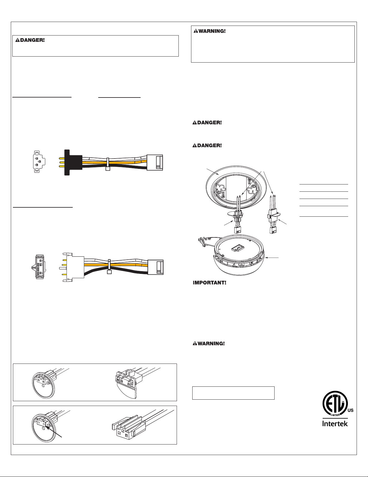
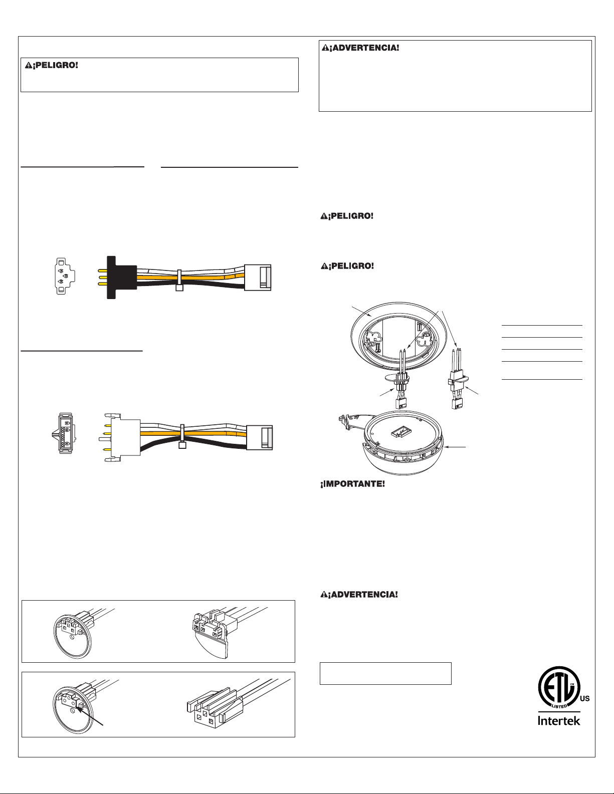
Improper wiring of the power connector or the wiring leading to
the power connector will cause damage to the Alar
m and may lead
to a non-functioning Alar
m.
2. Using wire nuts, connect the power connector to the AC power.
STAND ALONE ALARM ONLY:
•
Connect the white wire on the power connector to the neutral
wire in the junction box.
•
Connect the black wire on the power connector to the hot wire
i
n the junction box.
•
Tuck the orange wire inside the junction box.
I
t is used for
i
nterconnect only.
I
NTERCONNECTED ALARMS ONLY:
S
trip off about 1/2” of the plastic coating on the orange
i
nterconnect wire on the power connector.
• Connect the white wire on the power connector to the neutral
w
ire (usually white) in the junction box.
• Connect the black wire on the power connector to the hot wire
(
usually black) in the junction box.
• Connect the orange wire on the power connector to the inter-
c
onnect wire in the junction box. Repeat for each unit you are
i
nterconnecting. Never connect the hot or neutral wires in the
junction box to the orange interconnect wire. Never cross hot
a
nd neutral wires between interconnected Alarms.
6.
Make sure the Smoke/CO Alarm is receiving AC power. Under normal
operation, the green indicator light will shine continuously.
If the green
power indicator light does not light, TURN OFF POWER TO THE
JUNCTION BOX and recheck all connections. If all connections are
correct and the green power indicator still does not light when you
restore the power, the unit should be replaced immediately.
7.
ACTIVATING THE BATTERY BACK-UP
Activate the battery back-up by removing the “Pull to Activate
Battery Back-Up” tab. You do not need to open the battery
compartment and reposition the battery during installation.
DO NOT
remove the battery activation tab until AC power is turned on to
conserve battery power.
8. Single Station Alar
ms:
T
est each Alarm. Pr
ess and hold the
Test/Silence button until you hear the acknowledge “chirp” or the
unit alarms.
Interconnected Alarms: Press and hold the Test/Silence button
until the unit alarms. All interconnected Alarms should sound. The
other Alarms sounding only tests the interconnect signal between
Alarms. It does not test each Alarm’s operation. You must test each
Alarm individually to check if the Alarm is functioning properly.
If any unit in the series does not alarm during testing, TURN OFF POWER,
REMOVE BA
TTERIES, and r
echeck connections. If it does not alarm when
you restore power, replace it immediately.
STAND ALONE ALARM ONLY:
• If you are only installing one unit, restore power to the junction box.
INTERCONNECTED ALARMS ONLY:
• If you are interconnecting multiple Smoke/CO Alarms, repeat
Step 1-5 for each Smoke/CO Alarm in the series. When you are
finished, restore power to the junction box.
ELECTRICAL SHOCK HAZARD. Do not restore power until all
Alarms are completely installed. Restoring power before installation
is complete may result in serious electrical shock, injury or death.
HOW TO INSTALL THIS SMOKE/CO ALARM
I
NSTALLATION, Continued
3
3
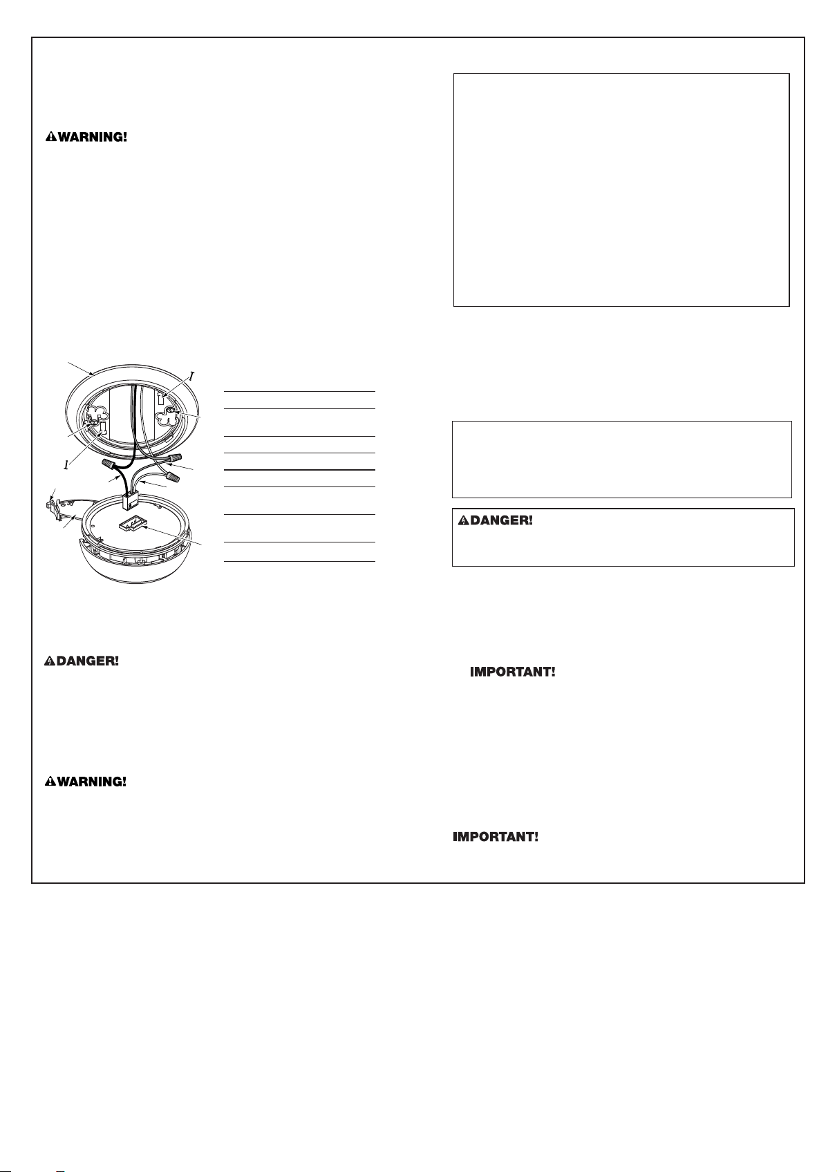
. Plug the power connector into the back of the Smoke/CO Alarm.
4.
Position the base of the Smoke/CO Alarm over the mounting bracket
a
nd turn. The Alarm will remain secure over a wide rotation range to
allow for perfect alignment. When wall mounting, this will allow fine-
t
uning on the positioning to compensate for out of aligned wall studs
a
nd to keep the wording level. The Alarm can be positioned over the
bracket every 120°. Rotate the Alarm until aligned properly.
5. Check all connections.
1
2
3
5
6
4
2
3
9
7
8
1 Mounting Bracket
2 Mounting Slot and Screw*
3 Locking Pins (break out of
bracket)
4 Hot (Black) AC Wire
5 N
eutral (White) AC Wire
6 Interc
onnect Wire (Orange)
7 Lever to Open Battery
Compartment
8 Swing-Out Battery
Compartment
9 Quick-Connect Power
*Not Included
PARTS OF THIS SMOKE/CO ALARM
SPECIAL REQUIREMENTS FOR INTERCONNECTED ALARMS
•
F
ailure to meet any of the above requirements could damage
the units and cause them to malfunction, removing your
p
rotection.
• AC and AC/DC Smoke/CO Alarms can be interconnected.
U
nder AC power, all units will alarm when one senses smoke
or CO. When power is interrupted, only the AC/DC units in
the series will continue to send and receive signals.
A
C powered Smoke/CO Alarms will not operate. See “Smart
Interconnect” Feature.
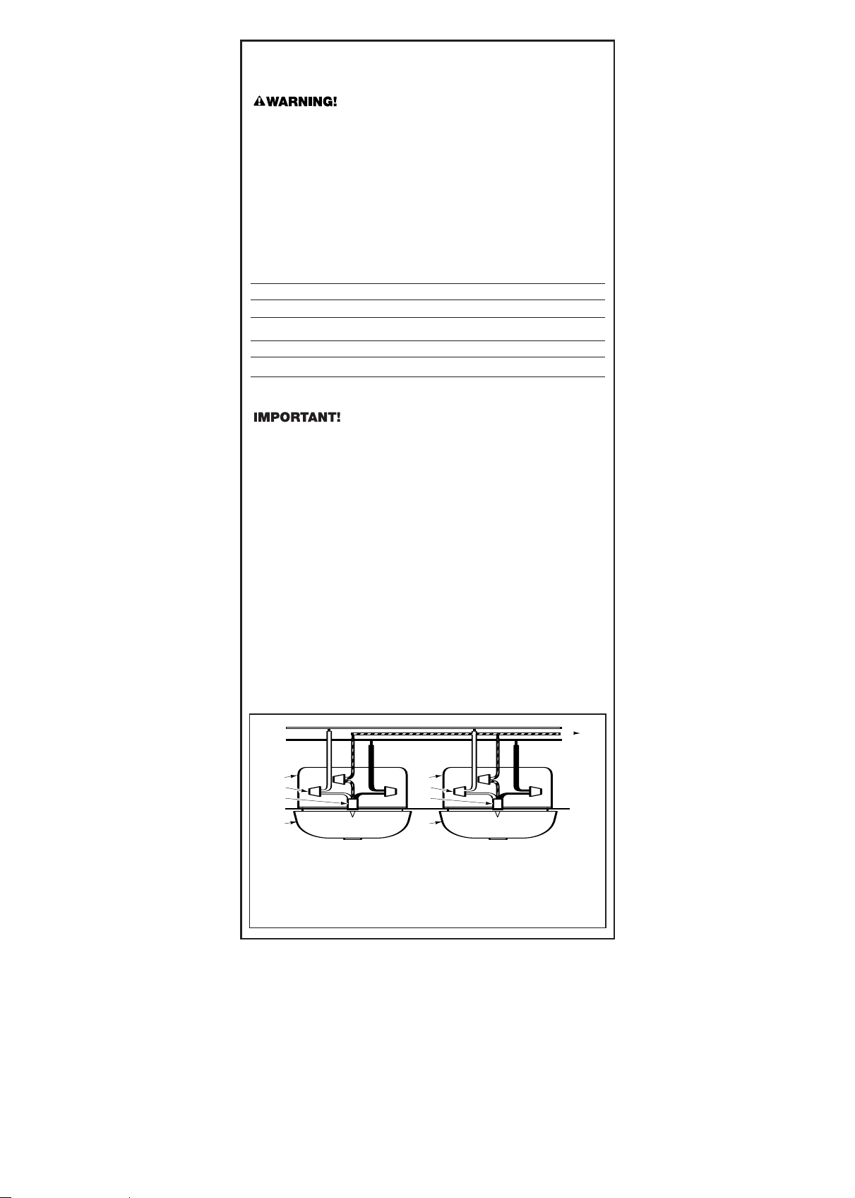
Interconnected units can provide earlier warning of a Smoke/CO problem
t
han stand-alone units, especially if the problem starts in a remote area of
the dwelling. If any unit in the series senses Smoke/CO, all units will alarm.
T
o determine which Smoke/CO Alarm initiated an alarm, refer to the table.
During an Alarm:
O
n Initiating Alarm(s) – Red LED(s) flashes (flash) rapidly
O
n All Other Alarms – Red LED is Off
After an Alarm (Latching):
O
n Initiating Alarm(s) – Green LED(s) On, Red LED(s) flash once every 5 seconds
On All Other Alarms – Green LED(s) On, Red LED(s) is Off
Compatible Interconnected Units
Interconnect units within a single family residence only. Otherwise all
households will experience unwanted alarms when you test any unit in the
series. Interconnected units will only work if they are wired to compatible
units and all requirements are met. This unit is designed to be compatible
with:
BRK Electronics
®
Smoke Alarm Models 9120, 9120B, 7010, 7010B,
7020B, 4120, 4120B, 4120SB, 4919, 2002RAC, 100S, 5919, 5919TH;
BRK Electronics
®
Heat Alarm Models HD6135F, HD6135FB; BRK
Electronics
®
CO Alarm Models CO5120BN, CO5120PDBN; Smoke/CO
Alarm Model SC6120B, SC9120B; and
First Alert
®
Smoke Alarm Models
SA4120, SA4120B, SA4121B, SA4919B, SA100B, SC7010B, SC7010BV;
Accessory devices models RM3, RM4, SL177.
Interconnected units must meet ALL of the following requirements:
• A maximum of 18 compatible BRK Electronics
®
Smoke, Heat or CO
Alarms may be interconnected. No more than 12 of the 18 can be
Smoke Alarms per NFPA 72.
• The same fuse or circuit breaker must power all interconnected units.
• The total length of wire interconnecting the units should be less
than 1000 feet (300 meters). This type of wire is commonly available
at Hardware and Electrical Supply stores.
• All wiring must conform to all local electrical codes and NFPA 70 of
the National Electrical Code. Refer to NFPA 72, NFPA 101, and/or
your local building code for further connection requirements.
6
7
8
4
3
1
5
4
3
1
5
2
A
B
}
}
A. Unswitched 120VAC B. To Additional Alarms,
60 Hz source Maximum = 18 Alarms
1. Smoke/CO Alarm
2. Ceiling or Wall
3. Power Connector
4. Wire Nut
5. Junction Box
6. Neutral Wire (White)
7. Interconnect Wire
(Orange)
8. Hot Wire (Black)
INSTALLATION, Continued
4
T
he optional locking features are designed to discourage unauthorized
removal of the battery or alarm. It is not necessary to activate the locks
i
n single-family households where unauthorized battery or alarm
r
emoval is not a concern.
These Smoke/CO Alarms have two separate locking features: one locks
the battery compartment, and the other locks the Smoke/CO Alarm to the
m
ounting bracket. You can choose to use either feature independently, or
use them both.
Tools you will need: • Needle-nose pliers or utility knife
• Standard/Flathead screwdriver.
USING THE OPTIONAL LOCKING FEATURES
T
HE BATTERY COMPARTMENT LOCK
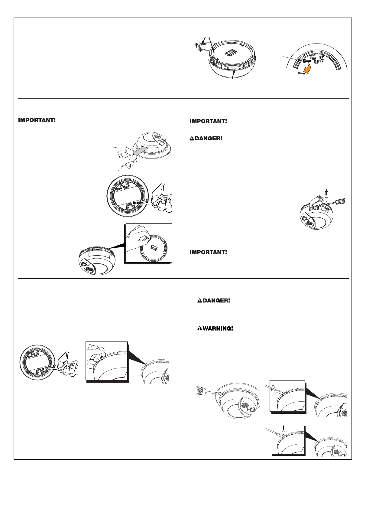
TO LOCK THE BATTERY COMPARTMENT:
D
o not lock the battery compartment until you have activated the battery
a
nd tested the battery back-up.
1. Activate the battery back-up by removing
the “Pull to Activate Battery Back-Up”
t
ab. Push and hold the test button on the
Smoke/CO Alarm’s cover until the alarm
sounds: 4 beeps, pause, 4 beeps, pause,
3
beeps, pause, 3 beeps, pause.
I
f the unit does not alarm during
testing, DO NOT lock the battery
compar
tment! Install a new battery
a
nd test again. If it still does not
a
larm, replace the Smoke/CO
Alarm immediately.
2. Using needle-nose pliers or a utility
knife, detach one locking pin from
t
he mounting bracket.
3. Push the locking pin through the
black dot on the label on the back
of the Smoke/CO Alarm.
TO DEACTIVATE THE BRACKET LOCK:
ELECTRICAL SHOCK HAZARD. Turn off the power to the area
where the Smoke/CO Alarm is installed before removing it from the
mounting bracket. Failure to turn off the power first may result in
serious electrical shock, injury or death.
Always discharge the branch circuit before servicing an AC or
AC/DC Smoke/CO Alarm. First, tur
n off the AC power at the circuit
breaker or fuse box. Next, remove the battery from Smoke/CO
Alar
ms with battery back-up. Finally, press and hold the test button.
1.
Insert a flathead screwdriver between the mounting bracket pin and
the mounting bracket.
2. Pry the Smoke/CO Alarm away from the bracket by turning both
the screwdriver and the Smoke/CO Alarm counterclockwise (left)
at the same time.
TO PERMANENTL
Y REMOVE
THE BRACKET LOCK:
Insert the flathead scr
ewdriver
between the locking pin and the
lock, and pry the pin out of the
lock.
THE MOUNTING BRACKET LOCK
TO ACTIVATE THE BRACKET LOCK:
1. Using needle-nose pliers, detach one locking pin from the mounting
bracket.
2. Insert the locking pin into the lock located on the base as shown in
the diagram.
3. When you attach the Smoke/CO Alarm to the mounting bracket,
the locking pin’s head will fit into a notch on the bracket.
TO UNLOCK THE BATTERY COMPARTMENT:
O
nce the Smoke/CO Alarm is installed, you must disconnect it from the AC
p
ower before unlocking the battery compartment.
ELECTRICAL SHOCK HAZARD. Turn off the power to the area where
t
he Smoke/CO Alarm is installed before removing it from the mounting
bracket. Failure to turn off the power first may result in serious electrical
shock, injury or death.
1
. Remove the Smoke/CO Alarm from the mounting bracket. If the unit is
locked to the bracket, see the section “To Deactivate the Locking
Feature.”
2.
Disconnect the power connector by gently prying it away from the back
o
f the Smoke/CO Alarm.
3. Insert a flathead screwdriver under the head of the
locking pin, and gently pry it out of the battery
c
ompartment lock. (If you plan to re-lock the
battery compartment, save the locking pin.)
4. To re
-lock the battery compartment, close the
battery door and reinsert the locking pin in the
lock.
5. Reconnect the power connector to the back of the Smoke/CO Alarm,
reattach the Smoke/CO Alarm to the mounting bracket, and restore the
power.
When replacing the battery, always test the Smoke/CO Alarm before
re-locking the battery compartment.
Mounting Bracket Lock
Battery Drawer Lock
L
ocking Pin
Both locking features use locking pins, molded into the mounting bracket. Using needle nose pliers or a utility knife, remove one or both pins, depending on
w
hich locking features you use.
5
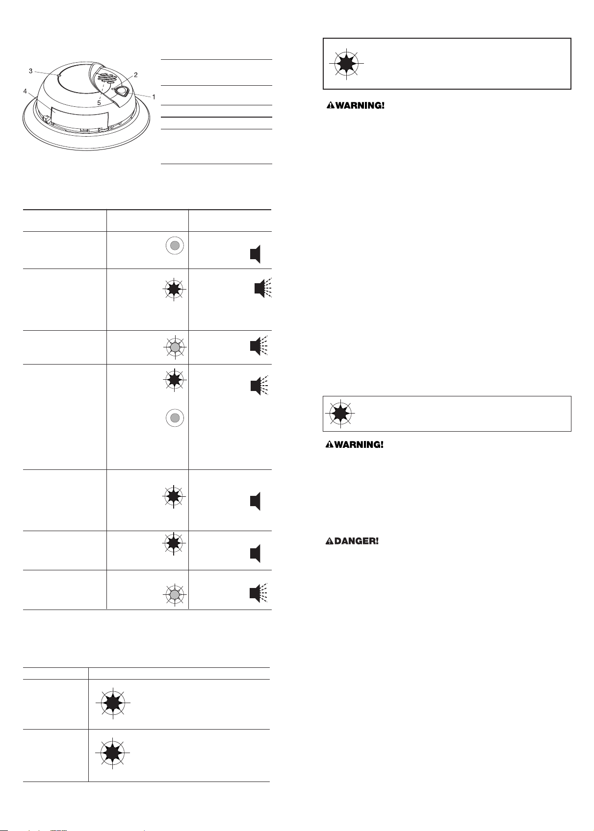
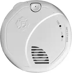
1
. Test/Silence Button: Press
and hold to activate test,
o
r to silence the alarm.
2
. POWER Light (GREEN)/
SMOKE ALARM Light (RED)
3
. CO ALARM Light (RED)
4. Battery Drawer
5
. (Behind the Cover) Alarm
Horn: 85dB audible alarm
f
or test, alarm, and unit
m
alfunction warning.
6
HOW YOUR SMOKE/CO ALARM WORKS
THE COVER OF YOUR SMOKE/CO ALARM
UNDERSTANDING THE LIGHT
AND HORN PATTERNS
Condition LED (Red or Green
L
ights)
Horn
P
OWER UP
Green LED
f
lashes ON
once, then
shines continuously
Horn remains silent
DURING TESTING
S
moke & CO
Red LEDs flash
o
nce every
s
econd during
t
heir respective
r
epetitive horn
pattern
s
H
orn pattern:
(Smoke) 3 beeps,
p
ause, 3 beeps,
p
ause;
(
CO) 4 beeps, pause,
4
beeps, pause
LOW OR MISSING
BATTERY
G
reen LED
flashes
(with horn)
H
orn “chirps”
about once a
minute
A
LARM CONDITION
Interconnected Series
of Smoke/CO Alarms
Smoke or CO
Red LED
flashes rapidly
on the unit that
triggered the alarm.
LEDs on the
other alarms in
an interconnected
series will not flash.
Horn pattern:
(CO) 4 beeps,
pause, 4 beeps,
pause repeating
on all CO Alarms and
“Smart Interconnect”
Alarms;
(Smoke) 3 beeps,
pause, 3 beeps,
pause repeating on all
Smoke, Heat, and
“Smart Interconnect”
Alarms
IN ALARM SILENCE
MODE
Red Smoke or CO
LED flashes
once every
second on
initiating unit
Horn remains silent:
CO for 4 minutes;
Smoke for up
to 15 minutes.
Horn will sound
if Smoke or CO
levels increase.
“LATCHING” ALARM
INDICATOR
Red Smoke
and/or CO
LED flashes
once every 5 seconds
Horn remains silent
MALFUNCTION
Gr
een LED flashes 3
times synchro-
nized with 3
rapid chirps
Hor
n sounds 3
consecutive
rapid chirps
every minute
W
HAT TO DO IF CARBON MONOXIDE IS DETECTED
I
F THE CO ALARM SOUNDS:
1. Operate the Test/Silence button.
2. Call your emergency services, fire department or 911. Write down
the number of your local emergency service here:
_____________________________________________________________
3. Immediately move to fresh air—outdoors or by an open door or
window. Do a head count to check that all persons are accounted
f
or. Do not re-enter the premises, or move away from the open door
or window until the emergency services responder has arrived, the
p
remises have been aired out, and your Smoke/CO Alarm remains
i
n its normal condition.
4
. After following steps 1-3, if your Smoke/CO Alarm reactivates within
a 24-hour period, repeat steps 1-3 and call a qualified appliance
t
echnician to investigate for sources of CO from fuel-burning
e
quipment and appliances, and inspect for proper operation of
this equipment. If problems are identified during this inspection
h
ave the equipment serviced immediately. Note any combustion
e
quipment not inspected by the technician, and consult the
m
anufacturers’ instructions, or contact the manufacturers directly,
for more information about CO safety and this equipment. Make
s
ure that motor vehicles are not, and have not, been operating in
a
n attached garage or adjacent to the residence. Wr
ite down the
number of a qualified appliance technician here:
_____________________________________________________________
WHAT TO DO IF SMOKE IS DETECTED
• If the unit alarms and you are not testing the unit, it is warning
you of a potentially dangerous situation that requires your
immediate attention. NEVER ignore any alarm. Ignoring the
alarm may result in injury or death.
• Never disconnect the AC power to quiet an unwanted alarm.
Disconnecting the power disables the Alarm so it cannot
sense smoke. This will remove your protection. Instead, open
a window or fan the smoke away from the unit. The Alarm will
reset automatically.
• If the unit alar
ms get ever
yone out of the house immediately.
•
ELECTRICAL SHOCK HAZARD: Attempting to disconnect the
power connector from the unit when the power is on may result
in electrical shock, serious injury or death.
When an interconnected system of AC powered units is in alarm,
the alarm indicator light on the unit(s) that initiated the alarm will blink
rapidly. It will remain OFF on any remaining units.
If the unit alarms, get everyone out of the dwelling immediately.
If the unit alarms and you are certain that the source of smoke is not a
fire—cooking smoke or an extremely dusty furnace, for example—open a
nearby window or
door and fan the smoke away fr
om the unit. Use the
Silence Feature to silence the Alarm. This will silence the alarm, and
once the smoke clears the unit will reset itself automatically.
If you hear the alarm horn sound 3 beeps, pause, 3 beeps,
pause and the RED SMOKE light is flashing, smoke has
been detected. Evacuate everyone from the building.
Actuation of your CO Alarm indicates the presence of carbon
m
onoxide (CO) which can kill you. In other words, when your CO
A
larm sounds, you must not ignore it!
“ALARM-MOVE TO FRESH AIR”
If you hear the alarm horn sound 4 beeps, pause,
4
beeps, pause, and the RED CO light is flashing,
m
ove everyone to a source of fresh air.
IF YOUR SMOKE/CO ALARM SOUNDS
WHAT TO DO FIRST–IDENTIFY THE TYPE OF ALARM
Type of Alarm What You See and Hear
Carbon Monoxide CO Light:
(CO) Flashing RED
Horn: 4 beeps,
pause, 4 beeps,
pause
Smoke Smoke Light:
Flashing RED
Horn: 3 beeps,
pause, 3 beeps,
pause

7
WEEKLY TESTING
•
NEVER use an open flame of any kind to test this unit. You
m
ight accidentally damage or set fire to the unit or to your
h
ome. The built-in test switch accurately tests the unit’s
o
peration as required by Underwriters Laboratories, Inc.
(
UL). NEVER use vehicle exhaust! Exhaust may cause per-
manent damage and voids your warranty.
•
DO NOT stand close to the Alarm when the horn is sounding.
E
xposure at close range may be harmful to your hearing.
When testing, step away when horn starts sounding.
It is important to test this unit every week to make sure it is working
properly. Using the test button is the recommended way to test this
S
moke/CO Alarm.
1
. Push and hold the Test/Silence button on the cover until you hear a
“chirp.” The “chirp” marks the start of the self-test sequence.
2
. During testing, you will hear a loud, repeating horn pattern: 3 beeps,
p
ause, 3 beeps, pause, while the red smoke LED flashes. Then you
will hear a loud, repeating horn pattern: 4 beeps, pause, 4 beeps,
p
ause, while the red CO LED flashes.
3
. When testing a series of interconnected units you must test each
unit individually. Make sure all units alarm when each one is tested.
If the Smoke/CO Alarm does not test properly:
1
. Make sure the AC power is applied and battery is fresh and
i
nstalled correctly.
2. Be sure the alarm is clean and dust-free.
3
. Test the unit again.
I
f the Smoke/CO Alarm is still not working pro
perly, replace it immediately.
Refer to the “Limited Warranty” at the end of this manual.
I
f there is still a problem, do not try to fix the Alarm yourself.
T
his will void your warranty!
REGULAR MAINTENANCE
Use only the replacement batteries listed below. The unit may not
operate properly with other batteries. Never use rechargeable
batteries since they may not provide a constant charge.
This unit has been designed to be as maintenance-free as possible, but
there are a few simple things you must do to keep it working properly:
• Test it at least once a week.
• Clean the Smoke/CO Alarm at least once a month; gently vacuum
the outside of the Smoke/CO Alarm using your household vacuum’s
soft brush attachment. Test the Smoke/CO Alarm. Never use water,
cleaners or solvents since they may damage the unit.
• If the Smoke/CO Alarm becomes contaminated by excessive dirt,
dust and/or grime, and cannot be cleaned to avoid unwanted
alarms, replace the unit immediately.
• Relocate the unit if it sounds frequent unwanted alarms. See “Where
This Alarm Should Not Be Installed” for details.
• When the battery back-up becomes weak, the Alarm will “chirp”
about once a minute (the low battery warning). This warning should
last 7 days, but you should replace the battery immediately to
continue your protection.
This Alarm must have AC or battery
power to operate. If AC power fails, and the battery is dead
or missing, the Alarm cannot operate.
DO NOT spray cleaning chemicals or insect sprays dir
ectly on or near
the Alarm. DO NOT paint over the Alarm. Doing so may permanently
damage the Alarm.
CHOOSING A REPLACEMENT BATTERY:
Y
our Smoke/CO Alarm requires one standard 9V battery. The following
batteries are acceptable as replacements: Duracell #MN1604, (Ultra)
#MX1604; Eveready (Energizer) #522. These batteries are available
at many local retail stores.
Actual battery service life depends on the Smoke/CO Alarm and the
environment in which it is installed. All the batteries specified above
ar
e acceptable r
eplacement batteries for this unit. Regar
dless of the
manufactur
er’
s suggested battery life, you MUST replace the battery
immediately once the unit starts “chirping” (the “low battery warning”).
W
HAT TO DO IN CASE OF FIRE
•
Don’t panic; stay calm. Follow your family escape plan.
•
Get out of the house as quickly as possible. Don’t stop to get
dressed or collect anything.
•
Feel doors with the back of your hand before opening them.
If a door is cool, open it slowly. Don’t open a hot door. Keep doors
a
nd windows closed, unless you must escape through them.
•
Cover your nose and mouth with a cloth (preferably damp).
Take short, shallow breaths.
• Meet at your planned meeting place outside your home,
a
nd do a head count to make sure everybody got out safely.
•
Call the Fire Department as soon as possible from outside.
Give your address, then your name.
• Never go back inside a burning building for any reason.
• Contact your Fire Department for ideas on making your home safer.
Alarms have various limitations. See "General Limitations of
S
moke/CO Alarms" for details.
“
SMART INTERCONNECT” FEATURE
This Alarm includes "Smart Interconnect" which enables the Alarm to be
i
nterconnected with other BRK Smoke, Heat, and "Smart Interconnect"
C
O Alarms. When smoke is detected, all Alarms will sound the smoke
horn pattern. When CO is detected, "Smart Interconnect" Alarms will
s
ound the CO horn pattern. Alarms that do not have the "Smart
I
nterconnect" Feature will remain silent during a CO alarm.
USING THE SILENCE FEATURE
N
E
VER disconnect the power to your Smoke/CO Alarm to silence the
hor
n—use the Silence Feature. Disconnecting the Smoke/CO Alarm
r
emoves your protection! If the unit will not silence or if it stays in
s
ilence mode continuously, it should be replaced immediately.
• The Silence Feature is intended to temporarily silence the horn
while you identify and correct the problem. Do not use the
Silence Feature in emergency situations. It will not correct a CO
problem or extinguish a fire.
• To use the Silence Feature, press the Test/Silence button until
y
ou hear the acknowledge “chirp” or until the horn is silent.
• If the Test/Silence button is pressed while the Smoke/CO Alarm
is in the silence mode, the alarm will start sounding again.
To silence Alarms in an interconnected series:
To silence an interconnected series of Smoke/CO Alarms, you must
press the Test/Silence button on the initiating alarm (The unit with the
flashing red light; the red light will be off on all other Alarms.). If you
press the Test/Silence on any other Alarm, it will only silence that unit,
not the whole interconnected series.
WHEN THE SMOKE ALARM IS SILENCED...
The Smoke Alarm will remain silent for up to 15 minutes and then return
to normal operation. If the smoke has not cleared within the silence
period or if smoke increases to a critical level during the silence period,
the unit will go back into alarm.
Use the Silence Feature only if you are certain of the source of
smoke. If you are not certain of the source or a fire starts while
you are clearing smoke, evacuate the house immediately. Not
responding to an alarm can result in property loss, injury, or death.
WHEN THE CO ALARM IS SILENCED...
The CO Alarm will r
emain silent for 4 minutes. While the Alarm is
silenced, it will continue to monitor the air for CO. After 4 minutes, if CO
levels remain potentially dangerous the horn will start sounding again.
The Silence Feature is intended to temporarily silence the Alarm horn.
It will not corr
ect a CO pr
oblem.
LOW BATTERY SILENCE FEATURE
This Silence Feature can temporarily quiet the low battery warning
“chirp” for up to 8 hours if AC
power is pr
esent. Pr
ess the Test/Silence
button on the Alarm cover until you hear the acknowledge “chirp”.
Once the low battery warning “chirp” silence feature is activated, the
unit continues to flash the gr
een light once a minute for 8 hours. After
8 hours, the low battery “chirp” will r
esume.
The Alarm will continue to
operate as long as AC power is supplied. However, replace the battery
as soon as possible, to maintain protection in event of a power outage.
THE “LATCHING ALARM” INDICATOR:
The Latching Alarm Indicator is activated after an Alarm is exposed
to alarm levels of smoke or carbon monoxide. This feature will only
work with AC power
. After smoke or CO levels dr
op below alarm levels,
the red smoke or CO LED will begin to flash once every 5 seconds.
It will continue to flash or “latch” until you clear it by testing the alarm.
This featur
e helps emer
gency r
esponders, investigators, or service
technicians identify which unit(s) in your home were exposed to alarm
levels of smoke or carbon monoxide. This can help investigators
pinpoint the source of smoke or CO.
Interconnected Alarms. Latching Alarm Indicator shows which Alarm(s)
in the series were exposed to alarm levels of smoke or carbon monoxide.
The Latching Alarm Indicator stays ON until you clear it, so it can alert
you to an alarm that occurr
ed while you were away from home, even
though smoke or CO present in the air has dropped below alarm levels.
8
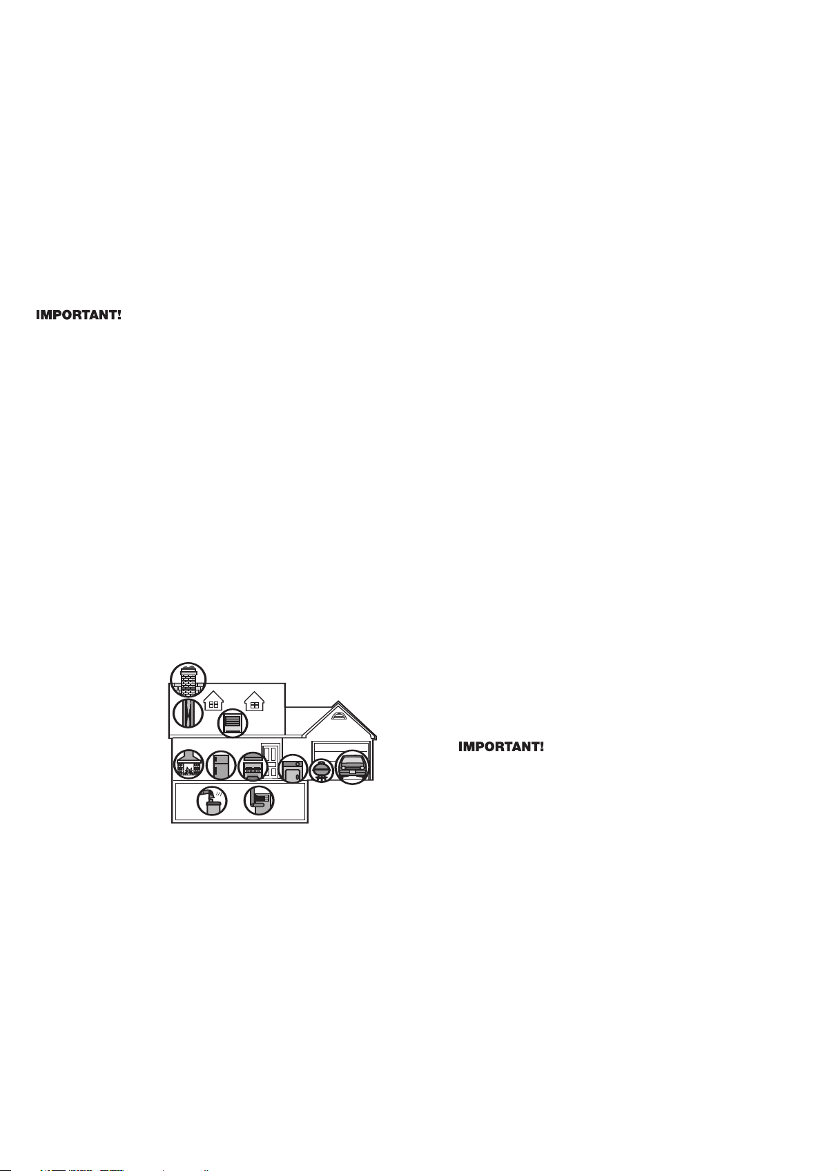
POTENTIAL SOURCES OF CO IN THE HOME
Fuel-burning appliances
like: portable heater,
gas or wood burning
fireplace, gas kitchen
range or cooktop, gas
clothes dryer.
Damaged or insufficient
venting:
corroded or
disconnected water
heater vent pipe, leaking
chimney pipe or flue, or
cracked heat exchanger,
blocked or clogged
chimney opening.
Improper use of appliance/device: operating a barbecue grill or
vehicle in an enclosed ar
ea (like a garage or scr
eened por
ch).
Transient CO Problems: “transient” or on-again-off-again CO problems
can be caused by outdoor conditions and other special cir
cumstances.
The following conditions can result in transient CO situations:
1. Excessive spillage or reverse venting of fuel appliances caused by
outdoor conditions such as:
• Wind direction and/or velocity, including high, gusty winds. Heavy
air in the vent pipes (cold/humid air with extended periods
between cycles).
•
Negative pressure differential resulting from the use of exhaust
fans.
• Several appliances running at the same time competing for limited
fr
esh air
.
• Vent pipe connections vibrating loose from clothes dryers,
fur
naces, or water heaters.
• Obstructions in or unconventional vent pipe designs which can
amplify the above situations.
2.
Extended operation of unvented fuel bur
ning devices (range, oven,
fireplace).
3. Temperature inversions, which can trap exhaust close to the ground.
4. Car idling in an open or closed attached garage, or near a home.
These conditions are dangerous because they can trap exhaust in your
home. Since these conditions can come and go, they are also hard to
r
ecr
eate during a CO investigation.
H
OW CAN I PROTECT MY FAMILY FROM CO
POISONING?
A
CO Alarm is an excellent means of protection. It monitors the air
and sounds a loud alarm before Carbon Monoxide levels become
t
hreatening for average, healthy adults.
A
CO Alarm is not a substitute for proper maintenance of home
appliances.
T
o help prevent CO problems and reduce the risk of CO poisoning:
•
Clean chimneys and flues yearly. Keep them free of debris, leaves,
and nests for proper air flow. Also, have a professional check for
r
ust and corrosion, cracks, or separations. These conditions can
p
revent proper air movement and cause backdrafting. Never “cap”
or cover a chimney in any way that would block air flow.
•
Test and maintain all fuel-burning equipment annually. Many local
gas or oil companies and HVAC companies offer appliance
inspections for a nominal fee.
•
Make regular visual inspections of all fuel-burning appliances.
Check appliances for excessive rust and scaling. Also check the
flame on the burner and pilot lights. The flame should be blue.
A
yellow flame means fuel is not being burned completely and
CO may be present. Keep the blower door on the furnace closed.
Use vents or fans when they are available on all fuel-burning
a
ppliances. Make sure appliances are vented to the outside. Do
not grill or barbecue indoors, or in garages or on screen porches.
• Check for exhaust backflow from CO sources. Check the draft
h
ood on an operating furnace for a backdraft. Look for cracks on
furnace heat exchangers.
• Check the house or garage on the other side of shared wall.
•
Keep windows and doors open slightly. If you suspect that CO
i
s escaping into your home, open a window or a door. Opening
windows and doors can significantly decrease CO levels.
I
n addition, familiarize yourself with all enclosed materials. Read
this manual in its entirety, and make sure you understand what to
d
o if your CO Alarm sounds.
REGULATORY INFORMATION FOR
SMOKE/CO ALARMS
REGULATORY
INFORMATION FOR CO ALARMS
WHAT LEVELS OF CO CAUSE AN ALARM?
Underwriters Laboratories Inc. Standard UL2034 requires residential CO
Alarms to sound when exposed to levels of CO and exposure times as
described below. They are measured in parts per million (ppm) of CO
over time (in minutes).
UL2034 Required Alarm Points*:
• If the alarm is exposed to 400 ppm of CO, IT MUST ALARM
BETWEEN 4 and 15 MINUTES.
• If the alarm is exposed to 150 ppm of CO, IT MUST ALARM
BETWEEN 10 and 50 MINUTES.
• If the alarm is exposed to 70 ppm if CO, IT MUST ALARM
BETWEEN 60 and 240 MINUTES.
* Approximately 10% COHb exposure at levels of 10% to 95% Relative
Humidity (RH).
The unit is designed not to alarm when exposed to a constant level
of 30 ppm for 30 days.
CO Alarms are designed to alarm before there is an immediate life threat.
Since you cannot see or smell CO, never assume it’
s not pr
esent.
• An exposure to 100 ppm of CO for 20 minutes may not affect
average, healthy adults, but after 4 hours the same level may
cause headaches.
• An exposure to 400 ppm of CO may cause headaches in average,
healthy adults after 35 minutes, but can cause death after 2 hours.
Standar
ds:
Underwriters Laboratories Inc. Single and Multiple Station
carbon monoxide alarms UL2034.
According to Underwriters Laboratories Inc. UL2034, Section 1-1.2:
“Carbon monoxide alarms covered by these requirements are intended
to respond to the presence of carbon monoxide from sources such as,
but not limited to, exhaust fr
om inter
nal-combustion engines, abnormal
operation of fuel-fired appliances, and fireplaces. CO Alarms are
intended to alarm at carbon monoxide levels below those that could
cause a loss of ability to react to the dangers of Carbon Monoxide
exposur
e.” This CO Alarm monitors the air at the Alarm, and is
designed to alarm befor
e CO levels become life thr
eatening. This
allows you precious time to leave the house and correct the problem.
This is only possible if Alarms are located, installed, and maintained as
described in this manual.
Gas Detection at T
ypical T
emperatur
e and Humidity Ranges:
The CO
Alarm is not formulated to detect CO levels below 30 ppm typically
.
Audible Alar
m:
85dB minimum at 10 feet (3 meters).
WHAT YOU NEED TO KNOW ABOUT CO
WHAT IS CO?
C
O is an invisible, odorless, tasteless gas produced when fossil fuels
do not burn completely, or are exposed to heat (usually fire). Electrical
a
ppliances typically do not produce CO.
T
hese fuels include:
W
ood, coal, charcoal, oil, natural gas, gasoline,
kerosene, and propane.
Common appliances are often sources of CO. If they are not properly
m
aintained, are improperly ventilated, or malfunction, CO levels can rise
q
uickly. CO is a real danger now that homes are more energy efficient.
“Air-tight” homes with added insulation, sealed windows, and other
w
eatherproofing can “trap” CO inside.
SYMPTOMS OF CO POISONING
T
hese symptoms are related to CO POISONING and should be
discussed with ALL household members.
Mild Exposure: Slight headache, nausea, vomiting, fatigue (“flu-like”
s
ymptoms).
M
edium Exposure:
T
hrobbing headache, drowsiness, confusion, fast
h
eart rate.
Extreme Exposure: Convulsions, unconsciousness, heart and lung
f
ailure. Exposure to Carbon Monoxide can cause brain damage, death.
This CO Alarm measures exposure to CO over time. It alarms if CO
levels are extremely high in a short period of time, or if CO levels reach
a
certain minimum over a long period of time. The CO Alarm generally
sounds an alarm before the onset of symptoms in average, healthy
adults.
W
hy is this important? Because you need to be warned of a potential
C
O problem while you can still react in time. In many reported cases of
CO exposure, victims may be aware that they are not feeling well, but
b
ecome disoriented and can no longer react well enough to exit the
b
uilding or get help. Also, young children and pets may be the first
a
ffected. The average healthy adult might not feel any symptoms when
t
he CO Alarm sounds. However, people with cardiac or re
spiratory
pro
blems, infants, unborn babies, pregnant mothers, or elderly people
c
an be more quickly and severely affected by CO. If you experience
e
ven mild symptoms of CO poisoning, consult your doctor immediately!
FINDING THE SOURCE OF CO AFTER AN ALARM
Carbon monoxide is an odorless, invisible gas, which often makes it
difficult to locate the source of CO after an alarm. These are a few of
the factors that can make it difficult to locate sources of CO:
• House well ventilated before the investigator arrives.
• Problem caused by “backdrafting.”
• Transient CO problem caused by special circumstances.
Because CO may dissipate by the time an investigator arrives, it may
be difficult to locate the source of CO.
BRK Brands, Inc. shall not be
obligated to pay for any carbon monoxide investigation or service
call.
R
EGULATORY INFORMATION FOR SMOKE ALARMS
R
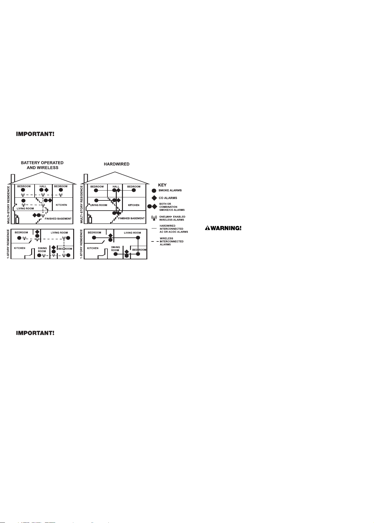
ECOMMENDED LOCATIONS FOR SMOKE ALARMS
I
nstalling Smoke Alarms in Single-Family Residences
T
he National Fire Protection Association (NFPA), recommends one
Smoke Alarm on every floor, in every sleeping area, and in every bed-
r
oom. In new construction, the Smoke Alarms must be AC powered and
i
nterconnected. See “Agency Placement Recommendations” for details.
For additional coverage, it is recommended that you install a Smoke
A
larm in all rooms, halls, storage areas, finished attics, and basements,
w
here temperatures normally remain between 40˚ F (4˚ C) and 100˚ F
(38˚ C). Make sure no door or other obstruction could keep smoke from
r
eaching the Smoke Alarms.
M
ore specifically, install Smoke Alarms:
•
On every level of your home, including finished attics and basements.
• Inside every bedroom, especially if people sleep with the door partly
o
r completely closed.
•
In the hall near every sleeping area. If your home has multiple
s
leeping areas, install a unit in each. If a hall is more than 40 feet
long (12 meters), install a unit at each end.
• At the top of the first-to-second floor stairway, and at the bottom of
t
he basement stairway.
S
pecific requirements for Smoke Alarm installation vary from state to
s
tate and from region to region. Check with your local Fire Department
for current requirements in your area.
It is recommended AC or AC/DC
u
nits be interconnected for added protection.
9
INST
ALLING SMOKE ALARMS IN MOBILE HOMES &
RVS
For minimum security install one Smoke Alarm as close to each sleeping
area as possible. For more security, put one unit in each room. Many
older mobile homes (especially those built before 1978) have little or no
insulation. If your mobile home is not well insulated, or if you are unsure
of the amount of insulation, it is important to install units on inside walls
only. Smoke Alarms should be installed where temperatures normally
remain between 40˚ F (4˚ C) and 100˚ F (38˚ C).
WARNING: Test units
used in RVs after the vehicle has been in storage, before every trip,
and once a week while in use. Failure to test units used in RVs as
described may remove your protection.
This equipment should be installed in accordance with NFPA (National
Fire Protection Association) 72 and 101. National Fire Protection
Association, One Batterymarch Park, Quincy
, MA 02269-9101.
Additional
local building and regulatory codes may apply in your area. Always
check compliance requirements before beginning any installation.
AGENCY PLACEMENT RECOMMENDATIONS
NFP
A 72 (National Fire Code)
Smoke Alarms shall be installed in each separate sleeping r
oom, outside
each sleeping area in the immediate vicinity of the bedrooms and on each
additional story of the family living unit, including basements and excluding
crawl spaces and unfinished attics.
In new construction, Alarms shall be so arranged that operation of any
one Alarm shall cause the operation of all Alarms within the dwelling.
Smoke Detection-Ar
e Mor
e Smoke Alar
ms Desirable?
The r
equir
ed
number of Smoke Alarms might not provide reliable early warning
pr
otection for those ar
eas separated by a door fr
om the areas protected
by the required Smoke Alarms. For this reason, it is recommended that
the householder consider the use of additional Smoke Alarms for those
ar
eas for incr
eased pr
otection. The additional ar
eas include the base
-
ment, bedr
ooms, dining room, furnace room, utility room, and hallways
not protected by the required Smoke Alarms. The installation of Smoke
Alarms in kitchens, attics (finished or unfinished), or garages is not
normally r
ecommended, as these locations occasionally experience
conditions that can result in improper operation.
California State Fire Marshal (CSFM)
Early warning detection is best achieved by the installation of fire detection
equipment in all rooms and areas of the household as follows: A Smoke
Alarm installed in each separate sleeping area (in the vicinity, but outside
bedr
ooms), and Heat or Smoke Alarms in the living r
ooms, dining r
ooms,
bedrooms, kitchens, hallways, finished attics, furnace rooms, closets, utility
and storage r
ooms, basements, and attached garages.
A
BOUT SMOKE ALARMS
Battery (DC) operated Smoke Alarms: Provide protection even when
e
lectricity fails, provided the batteries are fresh and correctly installed.
U
nits are easy to install, and do not require professional installation.
However, they do not provide interconnected functionality.
AC powered Smoke Alarms: Can be interconnected so if one unit
s
enses smoke, all units alarm. They do not operate if electricity fails.
A
C with battery (DC) back-up:
w
ill operate if electricity fails, provided
the batteries are fresh and correctly installed. AC and AC/DC units
m
ust be installed by a qualified electrician.
Wireless Interconnected Alarms: Offer the same interconnected
functionality as with hardwired alarms, without wires. Units are easy
t
o install and do not require professional installation. They provide
protection even when electricity fails, provided the batteries are fresh
and correctly installed.
S
moke Alarms for Solar or Wind Energy users and battery backup
power systems:
AC powered Smoke Alarms should only be operated
w
ith true or pure sine wave inverters. Operating this Smoke Alarm with
m
ost battery-powered UPS (uninterruptible power supply) products or
square wave or “quasi sine wave” inverters
will damage the Alarm.
I
f you are not sure about your inverter or UPS type, please consult with
t
he manufacturer to verify.
S
moke Alarms for the hearing impaired:
S
pecial purpose Smoke
Alarms should be installed for the hearing impaired. They include a
v
isual alarm and an audible alarm horn, and meet the requirements of
t
he Americans With Disabilities Act. These units can be interconnected
so if one unit senses smoke, all units alarm.
S
moke alarms are not to be used with detector guards
u
nless the
c
ombination has been evaluated and found suitable for that purpose.
All these Smoke Alarms are designed to provide early warning of fires if
l
ocated, installed and cared for as described in the user’s manual, and if
s
moke re
aches the Alarm. If you are unsure which type of unit to install,
refer to NFPA (National Fire Protection Association) 72 (National Fire
A
larm Code) and NFPA 101 (Life Safety Code). National Fire Protection
A
ssociation, One Batterymarch Park, Quincy, MA 02269-9101.
L
ocal
building codes may also require specific units in new construction
or in different areas of the home.
SPECIAL COMPLIANCE CONSIDERATIONS
This unit alone is not a suitable substitute for complete fire
detection systems in places housing many people—like apartment
buildings, condominiums, hotels, motels, dormitories, hospitals,
long-term health care facilities, nursing homes, day care facilities,
or group homes of any kind—even if they were once single-family
homes. It is not a suitable substitute for complete fire detection
systems in warehouses, industrial facilities, commercial buildings,
and special-purpose non-residential buildings which require special
fire detection and alarm systems. Depending on the building codes
in your area, this unit may be used to provide additional protection
in these facilities.
The following information applies to all four types of buildings listed
below:
In new construction, most building codes require the use of AC or
AC/DC powered Smoke Alarms only. AC, AC/DC, or DC powered
Smoke Alarms can be used in existing construction as specified by
local building codes. Refer to NFPA 72 (National Fire Alarm Code) and
NFPA 101 (Life Safety Code), local building codes, or consult your Fire
Department for detailed fire protection requirements in buildings not
defined as “households.”
1. Single-Family Residence:
Single family home, townhouse. It is recommended this unit be installed
on every level of the home, in every bedroom, and in each bedroom
hallway.
2. Multi-Family or Mixed Occupant Residence:
Apartment building, condominium. This unit is suitable for use in individual
apartments or condos, provided a primary fire detection system already
exists to meet fire detection requirements in common areas like lobbies,
hallways, or por
ches.
Using this unit in common ar
eas may not pr
ovide
sufficient warning to all residents or meet local fire protection ordinances/
regulations.
3. Institutions:
Hospitals, day car
e facilities, long-term health care facilities. This unit is
suitable for use in individual patient sleeping/r
esident r
ooms, pr
ovided
a primary fire detection system already exists to meet fire detection
requirements in common areas like lobbies, hallways, or porches.
Using this unit in common areas may not provide sufficient warning to
all r
esidents or meet local fir
e protection ordinances/regulations.
4. Hotels and Motels:
Also boarding houses and dormitories. This unit is suitable for use
inside individual sleeping/resident rooms, provided a primary fire
detection system alr
eady exists to meet fir
e detection r
equir
ements
in common areas like lobbies, hallways, or porches. Using this unit in
common areas may not provide sufficient warning to all residents or
meet local fire protection ordinances/regulations.

GENERAL LIMITATIONS OF SMOKE/CO ALARMS
This Smoke/CO Alarm is intended for residential use. It is not intended
f
or use in industrial applications where Occupational Safety and Health
A
dministration (OSHA) requirements for Carbon Monoxide Alarms must
be met. The Smoke Alarm portion of this device is not intended to alert
h
earing impaired residents. Special purpose Smoke Alarms should be
i
nstalled for hearing impaired residents (CO Alarms are not yet available
for the hearing impaired).
Smoke/CO Alarms may not waken all individuals. Practice the
e
scape plan at least twice a year, making sure that everyone is involved
–
from kids to grandparents. Allow children to master fire escape
planning and practice before holding a fire drill at night when they are
s
leeping. If children or others do not readily waken to the sound of the
S
moke/CO Alarm, or if there are infants or family members with mobility
limitations, make sure that someone is assigned to assist them in fire
d
rill and in the event of an emergency. It is recommended that you hold
a
fire drill while family members are sleeping in order to determine their
response to the sound of the Smoke/CO Alarm while sleeping and
t
o determine whether they may need assistance in the event of an
e
mergency.
S
moke
/
CO
A
larms cannot work without power.
B
attery operated units
cannot work if the batteries are missing, disconnected or dead, if the wrong
t
ype of batteries are used, or if the batteries are not installed correctly.
AC units cannot work if the AC power is cut off for any reason (open fuse
or circuit breaker, failure along a power line or at a power station, electrical
f
ire that burns the electrical wires, etc.). If you are concerned about the
limitations of battery or AC power, install both types of units.
This Smoke/CO Alarm will not sense smoke or CO that does not
reach the sensors.
It will only sense smoke or CO at the sensor. Smoke
o
r CO may be present in other areas. Doors or other obstructions may
affect the rate at which CO or smoke reaches the sensors. If bedroom
doors are usually closed at night, we recommend you install an alarm
d
evice (Combination CO and Smoke Alarm, or separate CO Alarms and
Smoke Alarms) in each bedroom and in the hallway between them.
This Smoke/CO Alarm may not sense smoke or CO on another
level of the home.
Example: This alarm device, installed on the second
floor,
may not sense smoke or CO in the basement. For this reason,
one alarm device may not give adequate early warning. Recommended
m
inimum protection is one alarm device in every sleeping area, every
b
edroom, and on every level of your home. Some experts recommend
battery powered Smoke and CO Alarms be used in conjunction with
i
nterconnected AC powered Smoke Alarms. For details, see “About
S
moke Alarms” for details.
S
moke/CO Alarms may not be heard.
T
he alarm horn loudness
meets or exceeds current UL standards of 85 dB at 10 feet (3 meters).
H
owever, if the Smoke/CO Alarm is installed outside the bedroom, it
m
ay not wake up a sound sleeper or one who has recently used drugs
or has been drinking alcoholic beverages. This is especially true if the
d
oor is closed or only partly open. Even persons who are awake may
n
ot hear the alarm horn if the sound is blocked by distance or closed
doors. Noise from traffic, stereo, radio, television, air conditioner, or
o
ther appliances may also prevent alert persons from hearing the alarm
h
orn. This Smoke/CO Alarm is not intended for people who are hearing
impaired.
The Alarm may not have time to alarm before the fire itself causes
d
amage, injury, or death, since smoke from some fires may not
reach the unit immediately. Examples of this include persons
smoking in bed, children playing with matches, or fires caused
b
y violent explosions resulting from escaping gas.
T
his Smoke/CO Alarm is not a substitute for life insurance.
Though this Smoke/CO Alarm warns against increasing CO levels or
the presence of smoke, BRK Brands, Inc. does not warrant or imply in
a
ny way that they will protect lives. Homeowners and renters must still
insure their lives.
This Smoke/CO Alarm has a limited life. Although this Smoke/CO
Alarm and all of its parts have passed many stringent tests and are
d
esigned to be as reliable as possible, any of these parts could fail at
any time. Therefore, you must test this device weekly. The unit should
be replaced immediately if it is not operating properly.
This Smoke/CO Alarm is not foolproof. Like all other electronic
d
evices, this Smoke/CO Alarm has limitations. It can only detect smoke
or CO that reaches the sensors. It may not give early warning of the
s
ource of smoke or CO is in a remote part of the home, away from the
a
larm device.
Once a minute, the alarm sounds 3 quick
“chirps”, and the green light flashes quickly
thr
ee times.
MALFUNCTION SIGNAL. Unit needs to be
replaced. Based on self-diagnostic tests, the
unit has detected a fault.
Units under warranty should be r
eturned to
manufacturer for replacement. See “Limited
W
arranty” for details.
Once a minute, the Green light flashes and the
horn “chirps”.
Low battery warning. Battery is low or missing. Replace the battery, avoid interrupting AC
power.
If your Alarm does this... It means... You should...
Green light is OFF. Unit will not alarm when you
press the Test/Silence button.
Unit may not be receiving any power.
Check the AC power supply. Make sure the
power connector is securely attached to the
alarm. Make sure a fresh 9V battery is installed
to power the battery back-up
*.
Green light flashes ON, once a minute (horn is
silent).
Alarm is not receiving AC power.
Unit is operating on battery back-up.
Check the AC power supply.
TROUBLESHOOTING GUIDE
Alarm goes back into alarm after you pressed
the T
est/Silence button to silence an alarm.
Smoke and/or CO levels are still potentially
danger
ous.
Refer to “If Your Smoke/CO Alarm Sounds” for
details on how to r
espond to an alarm. If anyone
is feeling ill, EVACUATE your home immediately
and call 911.
If you have any questions that cannot be answered by reading this manual, call Consumer Affairs: 1-800-323-9005.
*For a list of acceptable replacement batteries, see “Regular Maintenance.”
Alarm sounds frequently even though no high
levels of smoke or CO are revealed in an
investigation.
The Alarm may be improperly located. Refer to
“Where to Install This Alarm.”
Relocate your alarm. If frequent alarms continue,
have home rechecked for potential problems.
You may be experiencing an intermittent smoke
or CO problem.
ELECTRICAL SHOCK HAZARD. Turn off the power to the area where the Alarm is installed BEFORE removing it from the mounting bracket or
checking any electrical connections! Failure to turn off the power first may result in serious electrical shock, injury or death.
10

Printed in Mexico M08-0094-006 K1 08/08
BRK Electronics
®
is a registered trademark of BRK Brands, Inc.
First Alert
®
is a r
egistered trademark of the First Alert Trust.
11
LIMITED WARRANTY
B
RK Brands, Inc., ("BRK") the maker of BRK
®
b
rand and First Alert
®
b
rand products, warrants that for a period of five years from the date of purchase,
this product will be free from defects in material and workmanship. BRK, at its option, will repair or replace this product or any component of the product
f
ound to be defective during the warranty period. Replacement will be made with a new or remanufactured product or component. If the product is no
l
onger available, replacement may be made with a similar product of equal or greater value. This is your exclusive warranty.
T
his warranty is valid for the original retail purchaser from the date of initial retail purchase and is not transferable. Keep the original sales receipt.
Proof of purchase is required to obtain warranty performance. BRK dealers, service centers, or retail stores selling BRK products do not have the right to
a
lter, modify or any way change the terms and conditions of this warranty.
T
his warranty does not cover normal wear of parts or damage resulting from any of the following: negligent use or misuse of the product, use on improper
v
oltage or current, use contrary to the operating instructions, disassembly, repair or alteration by anyone other than BRK or an authorized service center.
Further, the warranty does not cover Acts of God, such as fire, flood, hurricanes and tornadoes or any batteries that are included with this unit.
BRK shall not be liable for any incidental or consequential damages caused by the breach of any express or implied warranty. Except to the extent
p
rohibited by applicable law, any implied warranty of merchantability or fitness for a particular purpose is limited in duration to the duration of the above
w
arranty. Some states, provinces or jurisdictions do not allow the exclusion or limitation of incidental or consequential damages or limitations on how long
an implied warranty lasts, so the above limitations or exclusion may not apply to you. This warranty gives you specific legal rights, and you may also have
o
ther rights that vary from state to state or province to province.
H
ow to Obtain Warranty Service
S
ervice:
I
f service is required, do not return the product to your retailer. In order to obtain warranty service, contact the Consumer Affairs Division at
1-800-323-9005, 7:30 AM - 5:00 PM Central Standard Time, Monday through Friday. To assist us in serving you, please have the model number and
date of purchase available when calling.
F
or Warranty Service return to:
B
RK Brands, Inc., 25 Spur Drive, El Paso, TX 79906
B
attery:
B
RK Brands, Inc. make no warranty, express or implied, written or oral, including that of merchantability or fitness for any particular purpose
with respect to battery.
F
or your records, please record:
D
ate Purchased: _______________________________
Where Purchased: __________________________________________
Date Installed: ____________/____________Month/Year
Replacement date is five years after installation: ________/______
Month/Year
NOTE: End of Life Signal — Once the unit reaches the end of its
lifecycle, the MALFUNCTION SIGNAL will sound once a minute
to indicate the need to immediately replace the Alarm.