Loading ...
Loading ...
Types 912H, N, Y200H, N, and R922N
3
All the regulators have an internal relief valve
that opens when downstream pressure reaches
approximately 13 psig (0,90 bar) on regulators set at
10 psig (0,70 bar) or approximately 1 psig (0,07 bar)
on regulators set at 11-inches w.c. (0,03 mbar). When
the internal relief valve opens, gas escapes to the
atmosphere through the regulator’s vent. The internal
relief valve gives overpressure protection against
excessive build- up resulting from seat leakage due to
worn parts or chips of foreign material on the orice.
Some type of external overpressure protection must
be provided if inlet pressure will be high enough to
damage downstream equipment on nal-state service.
Common methods of external overpressure protection
include relief valves and series regulation.
installation precautions apply to vent assemblies as the
integral regulator vents covered previously.
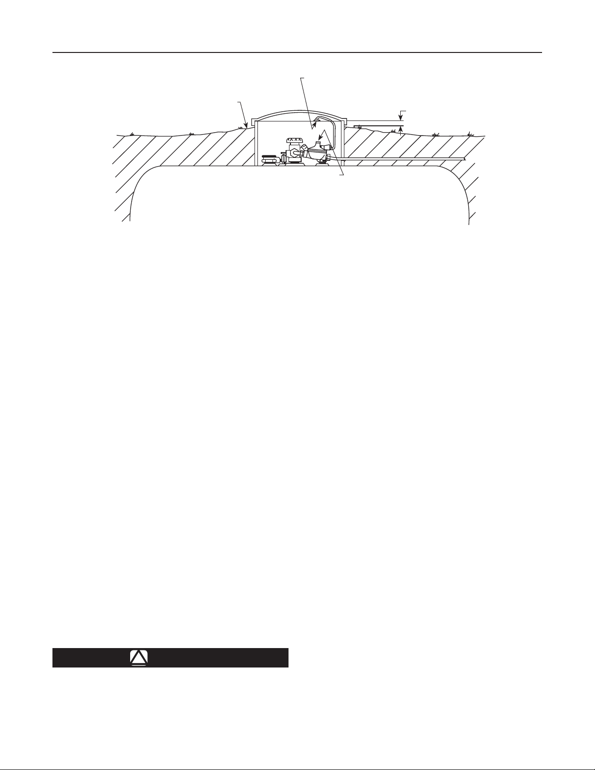
Underground container systems require a vent tube to
prevent water from entering the regulator spring case,
see Figure 3. Only the Types R922N and some 912s
can be used on underground installations because of the
need to use a vent tube. Remove the vent screen and
install the vent tube, such as a Fisher
®
Type P203. The
vent tube must be run from the regulator vent to above
the maximum water tube. The vent tube opening must
terminate at the extreme top inside of the dome cover.
Make sure the regulator’s closing cap is on tightly, and
maintain drainage away from the dome at all times.
For further information on underground installations,
write for a copy of “Underground LP-Gas Systems:
Suggested Installation, Inspection,” available from the
National LP-Gas Association, 1301 W. 22nd St., Oak
Brook, IL 60521.
Each regulator’s outlet pressure is factory-set. If
it becomes necessary to increase outlet pressure,
remove the closing cap, Figure 1, and turn the
adjusting screw clockwise. Turn the adjusting screw
counterclockwise to decrease the outlet pressure.
A pressure gauge is needed to determine the
regulator’s outlet setting after adjustment. Always
replace the closing cap after adjustment.
Figure 3. Regulators Installed on Underground Installations
Require a Vent Tube
!
Loading ...