Loading ...
Loading ...
Loading ...
Installation
Installation Steps
Installation
Installation Steps
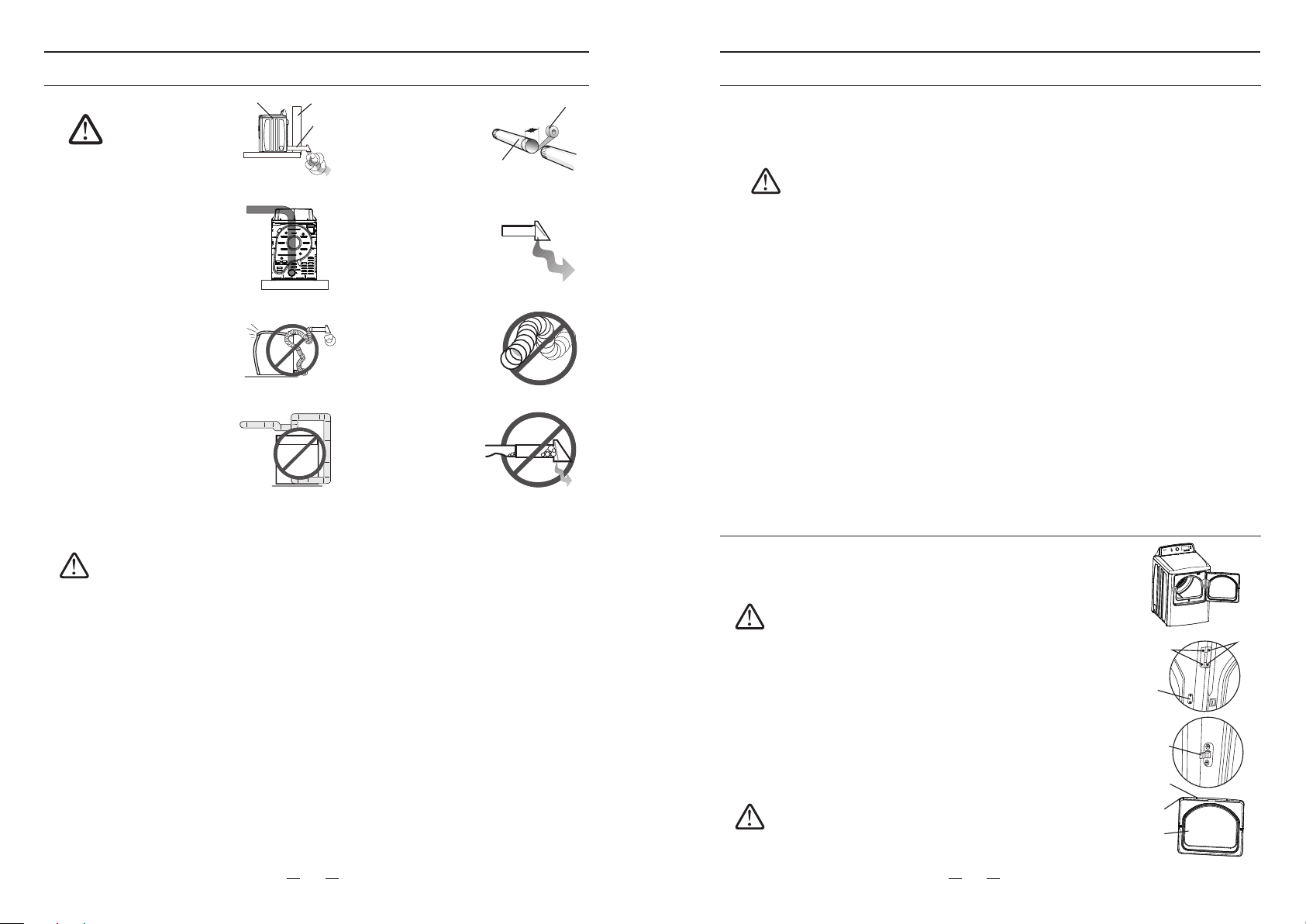
Dryer
Wall
Duct
exhaust
Make sure your
dryer is installed
properly so it
exhausts air
easily.
4"
Duct
Tape
Use a 4 inch. (10.2cm)
diameter rigid metal
duct. Tape all joints,
including at the dryer.
Never use lint-trapping
screws.
Keep ducts as
straight as
possible.
Clean all old ducts
before installing your
new dryer. Be sure the
vent flap opens and
closes freely. Inspect
and clean the exhaust
system annually.
WARNING
DO NOT
restrict your
dryer with a poor
exhaust system.
DO NOT use a plastic,
thin foil, or non-metal
flexible duct.
DO NOT
use
unnecessarily
long ducts that
have many
elbows.
DO NOT use
dented or clogged
ducts and vent.
5. Review the “Electric requirements” section on page 11.
BEFORE OPERATING OR TESTING, follow the grounding instructions in the
“Grounding” section on page 13.
U.S. Models:
Risk Of Electric Shock - All U.S. models are produced for a 3-WIRE SYSTEM
CONNECTION.
The dryer frame is grounded to the neutral conductor at the terminal block.
A 4-WIRE SYSTEM CONNECTION is required for new or remodeled construction,
mobile homes, or if local codes do not permit grounding through neutral conductor.
If the 4-wire system is used, the dryer frame cannot be grounded to the neutral
conductor at the terminal block. Refer to the “Electric requirements” section on
page 11 for 3-WIRE or 4-WIRE SYSTEM CONNECTIONS.
WARNING
Remove the terminal block cover plate.
Insert the power cord with a UL-listed strain relief through the hose provided in the
cabinet near the terminal block.
- A strain relief must be used.
Do not loosen the nuts already installed on the terminal block. Be sure they are tight.
Use a 3/8" (1cm) deep well socket.
6. [GAS MODELS ONLY]
Review the “Gas requirements” section on page 11. Remove the pipe thread
protective cap. Apply a pipe joint compound or about 1 ½” wraps of teflon tape over all
threaded connections.
- The pipe joint compound must be resistant to the actions of any liquefied petroleum
gas.
Connect the gas supply to your dryer. An additional fitting is required to connect the
3/4" (1.9cm) female thread end of a flexible connector to the 3/8" (1cm) male threaded
end on the dryer.
Securely tighten the gas line fitting over the threads.
Turn on the gas supply.
Check all gas connections for leaks using a soap solution.
If bubbles appear, tighten the connections and recheck. DO NOT use an open
flame to check for gas leaks.
WARNING
Your dryer is built to open from left to right. You can reverse
the direction (right to left) by following steps.
1. Unplug the power cord.
2. Remove the four screws connecting the body and hinges.
Door Reversal
7. Using a level, check your dryer and make the necessary adjustments to the leveling
legs.
8. Make sure all gas connections (Gas Models only), exhaust and electrical connections
are complete. Plug in your dryer.
9. [GAS MODELS ONLY]
The burner may not ignite initially due to air in the gas line. Allowing your dryer to
operate on a heat setting will purge the line. If the gas does not ignite within 5 minutes,
turn your dryer off and wait 5 minutes. Be sure the gas supply to your dryer has been
turned on. In order to confirm the gas ignition, check the exhaust for heat.
10. Final Installation Check
- Make sure the dryer is plugged into an electrical outlet and is properly grounded.
- The exhaust ductwork is hooked up and the joints are taped.
- A plastic flexible duct in NOT used.
- Use rigid or stiff-walled flexible metal vent material.
- The dryer is leveled and is sitting firmly on the floor.
- Gas models - the gas is turned on with no gas leakage.
- Start your dryer to confirm that it runs, heats, and shuts off.
Take care the door when removing and installing the
screws in case it drops and hurts you.
CAUTION
Screws for
hinge and
body
Screws for
hinge and
door
Locker
cover
3. Put the door aside. Remove the screws for locker cover on the
right body and screws for the locker on the left body.
4. Install the locker onto the right body with screws. Install the
locker cover onto the left body.
5. Remove all screws around the door.
6. Disassemble the inside door board from the outside door board.
o
7. Turn the inside door board 180 then install it with the outside
door board.
8. Fix the screws back onto the door sides except the hinges.
9. Install the hinges onto the body left with screws.
10. Install the door onto the unit body with handles right.
Locker
Screw
Outside
door
board
Inside
door
board
Take care the hinges and screws for door and body.
There are two different screws. Screws with flat head
are for hinges and door.
CAUTION
15
16
Loading ...
Loading ...
Loading ...