CFCH Electronic Control Panel
08/19425/2 (UK) Issue 2
The product complies with the European Safety Standards EN60335-2-30 and the European Standard Electromagnetic Compatibility (EMC) EN55014,
EN60555-2 and EN60555-3. These cover the essential requirements of EEC Directives 2006/95/EC and 2004/108/EC
1
54
6
7 8 9
2 3
a
b
c
d
e
f
61mm PCD
120mm
160mm
IMPORTANT SAFETY ADVICE
Always disconnect the supply before working on the Heater.
This product should be mounted safely onto a suitable wall.
The Control Panel may only be operated when mounted
horizontally on a wall.
The Control Panel should not be installed in a toilet or
washroom.
The Control Panel is not suitable for ceiling mounting.
Ensure that cables are of adequate current carrying capacity.
WARNING: Isolate electrical supply to ALL modular linked
units when carrying out maintenance.
General
The CFCH control panel is an electronic controller for use with the
electronic range of Dimplex Heaters. This control panel has a number of
integrated features such as, heat selection, timer, programming and frost
protection. Connectivity between heater and control panel is achieved
using LAN (Local Area Network) cable i.e. CAT5, CAT5E or CAT6, pin
configuration is straight through 1 to 1. This eases installation and
improves reliability considerably.
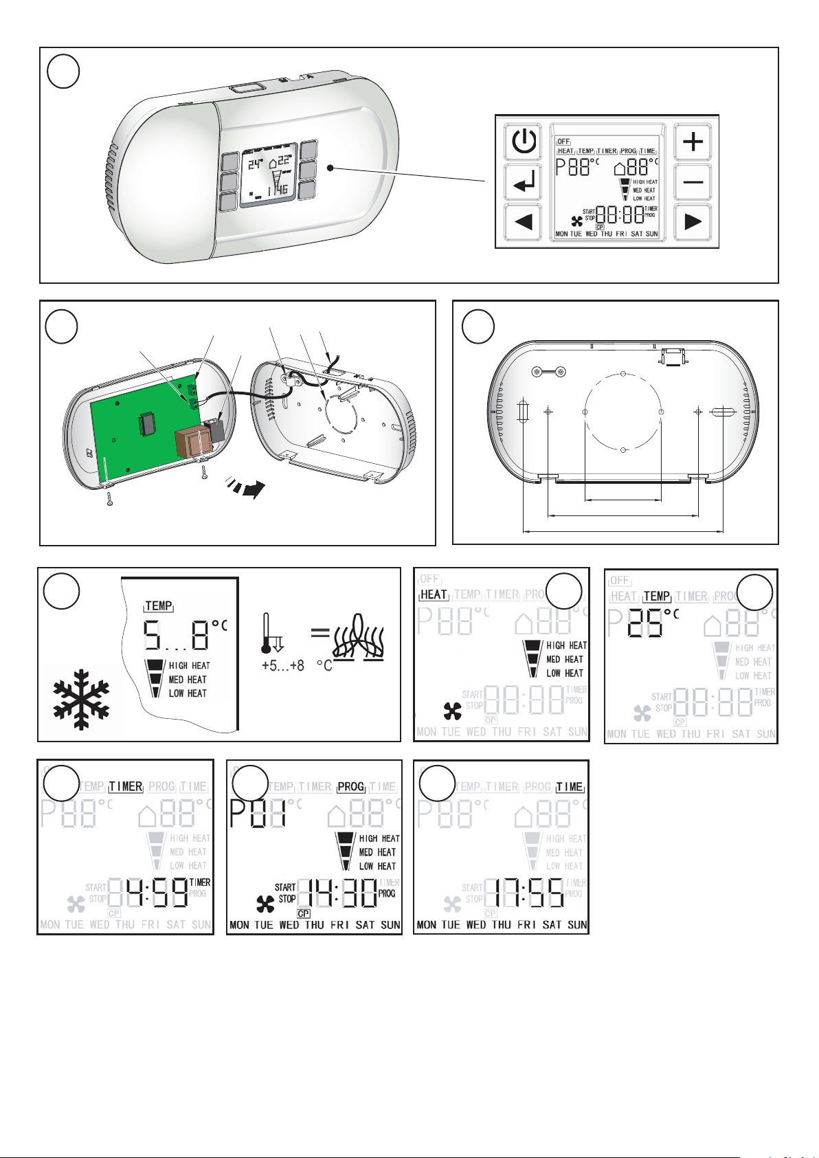
Electrical Connection - see Fig. 2.
The control panel must be supplied at terminal block ‘a’ with a ~230-240V
supply. The cable clamp ‘d’ is provided to ensure the mains cable ’f’ (at
least 2G x 0.75mm²) is secure. The LAN cable connecting the heater to
the control panel is fed to socket ‘c’ in a similar way to the power cable.
Note: The control panel should be protected by a suitable fuse.
Installation
The control panel should be mounted in a convenient location away from
direct sun light or draughty areas.
Surface Mounting
The control panel can be directly mounted onto a suitable wall. This is
done by removing the back cover and using it as a guide to mark off the
holes - see Fig. 3. Drill and plug the holes with suitable wall plugs.
Remove one of the knockouts on either the top or the bottom to allow
entry for the supply cables via surface trunking. Mount the back cover to
the wall and feed supply cables through the trunking and into the back
cover. Make the appropriate electrical and control connections to the
PCB as discussed in the Electrical Connection section. Clip the front
cover on and secure with the two screws provided in the direction
shown in Fig. 2. Turn on the supply and check the control functions.
Surface Mounting to a Recessed Box
The control panel can also be mounted onto standard single gang and
double gang backing boxes. The backing box (not supplied) should be
already recessed into the wall. Remove the large knock-out in the back
cover (see ‘e’ in Fig. 2) and secure it onto the backing box using the
holes provided - see Fig. 3. Feed the supply cables through the recessed
conduit into the recessed box and out into the back cover. Make the
appropriate electrical and control connections as discussed in the
Electrical Connection section. Clip the front cover on and secure with the
two screws provided in the direction shown in Fig. 2. Turn on the supply
and check the control functions.
Control Panel Power-up
When the controller is powered up for the first time, it will check if there
are heaters connected and that they are operational. When this check is
completed, an LED will light beside the screen (see Fig. 1) to show that
the system is functioning. If the LED does not light, check the following;
(1) The control panel is supplied with electrical power.
(2) The heater is supplied with electrical power.
(3) The LAN connection between the controller and the heater is
working.
NOTE : The controller will also perform this check after a power cut.
CFCH Control Functions - see Fig. 1.
The LCD display shows the following functions:
Main menu points: OFF, HEAT, TEMP, TIMER, PROG, and TIME.
Desired room temperature in °C (thermostat function)· Actual ambient
room temperature in °C.
Selectable heat settings COLD ( Fan only), LOW HEAT, MEDIUM
HEAT and HIGH HEAT.
Time display in format hh:mm – shown as 24h
Weekdays MON, TUE, WED, THU, FRI, SAT, SUN
Stand-by mode: the display shows time, day and room temperature.
Note: If the control panel is connected to a heater with only two heat
settings, LOW HEAT and MEDIUM heat will give the same output.
Short description of Menu functions
OFF: switching into stand-by mode.
HEAT: setting the desired heat position from cold ‘ ’ to max heat setting.
TEMP: pre selection of the desired room temperature from 5°C to 35°C.
TIMER: selection of the run back timer function (from 1 minute to 4 hours
59 minutes). When the selected time is over the unit will be in
stand-by mode.
PROG: selection of the programming mode. 32 individual programs can
be entered. This is a weekly timer where all functions of the unit
can be input and viewed.
TIME: setting the time and the weekdays.
Operation
With the unit plugged in, the heater can be switched on or into stand-by
mode by pressing the ‘stand-by’ button - see Fig. 1 for Controls
layout.
Heat settings (HEAT) - see Fig. 5.
Navigate the cursor to HEAT with the buttons. Press to
change the heat setting between , LOW HEAT, MEDIUM HEAT and
HIGH HEAT.
Thermostat (TEMP) - see Fig. 6.
Navigate the cursor to TEMP with the buttons. Press to set
the desired ambient temperature between 5°C and 35°C and press the
enter button . When the actual ambient temperature is higher than the
set temperature, the heater switches into stand-by mode automatically
until the actual room temperature falls below the thermostat setting.
Note: In order to switch off the heater, press the ‘stand-by’ button.
Runback timer (TIMER) - see Fig. 7.
Navigate the cursor to TIMER with the buttons.
Set the hours (0 to 4) with and press the enter button .
Then set the minutes (0 to 59) with and press the enter button .
The cursor must be positioned under the TIMER symbol (see Fig. 7) for
the runback timer to operate using the pre-set heat setting (see heat
settings). The heater will be switched into stand-by mode automatically
when the pre-set time is over.
Please Note : The heater only operates as long as the desired room
temperature is higher than the actual ambient temperature (see
Thermostat). The runback timer continues working even if the heater
has stopped heating up the room.
Program mode (PROG) - see Fig. 8
1. Navigate the cursor to PROG with the buttons and press
enter . Choose a program number between 1 and 32 with the
buttons and press enter .
2. Set the days with choosing either Single days, Monday until
Friday, Saturday and Sunday or Monday until Sunday. Press the enter
button to accept.
3. Set the program start time with and confirm the hours and
minutes with the enter button .
4. Set the program stop time with and confirm the hours and
minutes with the enter button .
Dimplex Industrial Fan Heater
Electronic Control Panel : CFCH
IMPORTANT: THESE INSTRUCTIONS SHOULD BE READ CAREFULLY AND RETAINED FOR FUTURE REFERENCE

Note: Always set start time before setting the stop time.
5. Set the desired ambient room temperature (thermostat setting) with
and confirm with the enter button .
6. Set the heat setting between (fan only) / LOW HEAT/ MEDIUM
HEAT and HIGH HEAT with the buttons and confirm with the
enter button .
7. All settings for the first program are now done. Enter a new program
according to the steps 1-6 or activate the already entered program by
leaving this menu with the button.
8. In order to continuously run the entered program the cursor must be
positioned under the PROG symbol. The heater will operate according
to the entered information. When a program is running, the program
number will appear with the pre-set and ambient temperatures
alternating.
9. An entered program can be checked, edited or deleted just by navigating
into the PROG menu and pressing the enter button. With the
buttons the different program numbers can be selected. When a
program number is selected (flashing) the start/stop time will alternate
according to any pre-entered information. To delete one program
number, press the button. The CP symbol (clear program) appears
and by pressing the enter button this program will be deleted.
leaves the menu without deleting the program.
Time setting (TIME) - see Fig. 9.
Navigate the cursor to TIME with the buttons. Press the enter
button to adjust the weekday with the buttons. Confirm with the
enter button and set the hours and minutes with . Press the enter
button or to leave the time menu.
Frost protection - see Fig. 4.
Choose a heat setting and set the desired ambient temperature between
5°C and 8°C (see ‘Operation’).
When the temperature falls below +5 °C…+8 °C, the heater switches on
automatically.
Cleaning
WARNING : ALWAYS DISCONNECT FROM THE POWER SUPPLY
BEFORE CLEANING THE HEATER
Do not use detergents, abrasive cleaning powders or polish of any kind
on the Controller.
Wipe with a dry cloth to remove dust and a damp cloth (not wet) to clean
off stains. Be careful not to allow moisture into the Controller.
Use a vacuum cleaner to remove any fluff which accumulates on top of
the Controller.
Care must be taken to avoid any moisture ingress into the product.
Recycling
For electrical products sold within the European Community.
At the end of the electrical products useful life it should not
be disposed of with household waste. Please recycle
where facilities exist. Check with your Local Authority or
retailer for recycling advice in your country.
After Sales Service
Your product is guaranteed for one year from the date of purchase.
Within this period, we undertake to repair or exchange this product free
of charge (excluding element & subject to availability) provided it has
been installed and operated in accordance with these instructions.
Your rights under this guarantee are additional to your statutory rights,
which in turn are not affected by this guarantee.
Should you require after sales information or assistance with this product
please go to www.dimplex.co.uk where you will find our self help
guide by clicking on “After Sales” or ring our helpdesk on 0845 600
5111 (UK) or 01 842 4833 (R.O.I.) .
Spare parts are also available on the website
www.dimplex.co.uk
Please retain your receipt as proof of purchase.
www.dimplex.co.uk
Republic of Ireland Tel. 01 8424833
Dimplex UK Ltd.
Millbrook House
Grange Drive
Hedge End
Southampton
Hampshire. SO30 2DF
[c] Dimplex UK Limited
All rights reserved. Material contained in this publication may not be reproduced in whole or in part, without prior permission in writing of Dimplex UK Limited.