Loading ...
Loading ...
Loading ...
English | 15
Bosch Power Tools 1 609 92A 1M8 | (11.1.17)
Operation
Sawing
Preparing for Operation
The saw station must be assembled depending on the respec-
tive sawing application:
– Sawing Panels (e. g. laminate flooring panels)
– Sawing Profiles (e. g. baseboards)
The use of screws/bolts is not required.
Panel (cross section) (see figures A1 – A3)
Mount the support extensions 6 left and right to the base unit
1.
Depending on the workpiece size, mount the additional sup-
ports 7 to the inner or outer guide of the support extensions.
Loosen the locking knob 3 a few turns.
Turn the locking lever 10 of the guide rail leftward and fold the
guide rail 4 upward.
Mark the desired cutting line on the workpiece.
Place down the workpiece with the visible side flat against the
stop of the base unit 1.
Fold the guide rail downward and align the workpiece to the
cutting line of mark 11.
Lock the guide rail 4 with locking lever 10.
Tighten the locking knob 3.
Panel (mitre cuts) (see figure B)
The mitre angle can be set in the range from 45° (left side) to
45° (right side).
Loosen locking knob 12.
Turn the guide rail 4 left or right until the angle indicator 13 in-
dicates the requested mitre angle.
Tighten the locking knob 12 again.
For swift and precise adjustment of standard mitre angles,
the guide rail engages at 0° and 45°.
For additional worksteps, see “Panel (cross section)” on
page 15.
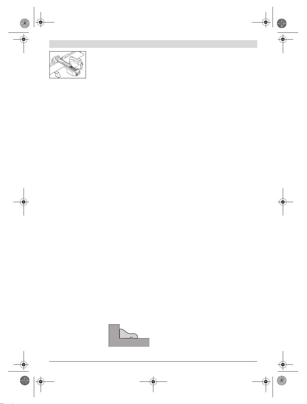
Profile(bevel cuts) (seefiguresC1–C3)
Mount the support extensions 6 left and right at the front po-
sition of the bridge 8.
Fold the red end stop 9 by 180° to the rear.
Loosen the locking knob 3 a few turns.
Turn the locking lever 10 of the guide rail leftward and fold the
guide rail 4 upward.
Mark the desired cutting line on the workpiece.
Place down the workpiece flat
against the stop of the support ex-
tensions 6.
Fold the guide rail downward and
align the workpiece to the cutting
line of mark 11.
Lock the guide rail 4 with locking lever 10.
Tighten the locking knob 3.
Adjust the base plate of the jigsaw accordingly to the desired
angle.
Notes on the adjustment are given in the operating instruc-
tions of the jigsaw.
Note: The folded back red end stop 9 is used as the stop for
the base plate of the power tool.
Panel (lengthway cuts, recesses) (see figure D)
Loosen the locking knob 3 a few turns.
Remove the guide rail 4 and the bridge 8 from the base unit 1.
Mount the support extensions 6 left and right to the base unit
1.
Depending on the workpiece length, mount the additional
supports 7 reversed (see figure D) into the inner or outer
guide of the support extensions.
Take care that the cutting line in the notched area is be-
tween the additional supports, to ensure that you do
not saw into the saw station.
Note: When sawing lengthway cuts, the saw station is used
only as a supporting surface. The workpiece cannot be
clamped. Therefore, hold it tightly while sawing.
Working Advice
Only use the saw blades recommended by Bosch (see
page 127). When using saw blades that are too thin, dan-
ger is given that the cut runs out of centre.
The base plate of the jigsaw must always be in the front posi-
tion.
The thickness of the material to be cut depends on the sawing
capacity of the respective jigsaw.
For further information, see the operating instructions of your
jigsaw.
To ensure optimal operational safety, the workpiece must al-
ways be affixed.
Sawing
Position the base plate of the power tool in such a manner on
the guide rail 4 that you always saw in the direction of locking
knob 3.
Switch on the machine.
Saw through the workpiece applying uniform feed.
Switch off the machine and wait until the saw blade has come
to a complete stop.
Remove the power tool from the the guide rail and release the
workpiece.
Transport
Remove the power tool before transporting.
OBJ_BUCH-1219-003.book Page 15 Wednesday, January 11, 2017 1:29 PM
Loading ...
Loading ...
Loading ...