Loading ...
Loading ...
Loading ...
22 En
Connections
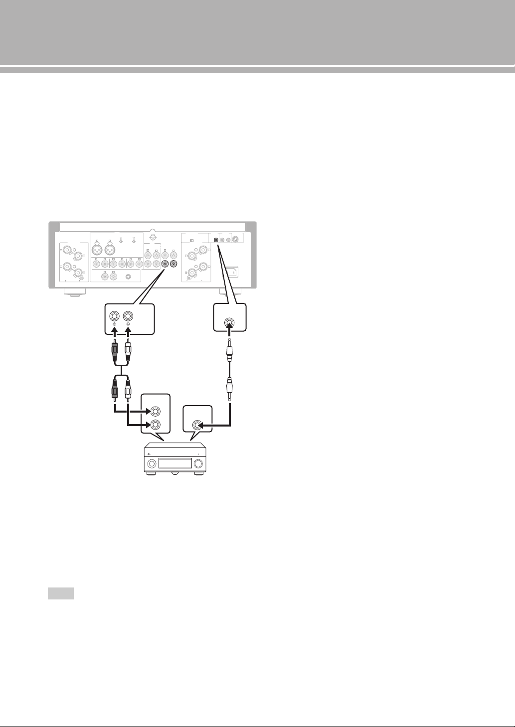
■ Connecting a component supporting
the trigger function such as a Yamaha
AV receiver
The operations of this unit can be controlled in
synchronization with the operations of the connected
component, such as a Yamaha AV receiver (power ON/
STANDBY or MAIN DIRECT input selection).
Connect the PRE OUT jacks and the TRIGGER OUT jack
of the Yamaha AV receiver to this unit as illustrated
below:
When the power of the connected component is turned on,
this unit turns on and the input is set to MAIN DIRECT
automatically.
When MAIN DIRECT is selected as the input source, this
unit enters STANDBY mode if the power of the connected
component is turned off.
To enable synchronization, turn off this unit before connecting
the component to the MAIN IN jacks. The synchronization
cannot be activated when the STANDBY/ON, OFF switch of the
unit has been set to OFF.
Note
GND
PHONO
LINE 1
CD
BAL
(-6dB)
ATT. IN V.
BYPASS NORMAL
PHASE
ATTENUATOR
INPUT
SPEAKERS R CH
A
B
+
+
A OR B:4 MIN. /SPEAKER
A+B:8 MIN. /SPEAKER
R L
R R
R
L
TUNER
LINE2
REC
PB
MAIN IN
L
L
L
R
R R
L
L
PRE OUT
AUTO POWER STANDBY
ON
OFF
SPEAKERS L CH
A
B
+
+
TRIGGER
REMOTE
SYSTEM CONNECTOR
IN IN OUT
AC IN
A OR B:4 MIN. /SPEAKER R
A+B:8 MIN. /SPEAKE
NORMAL (EIA)
+ HOT
- COLD
GND
12
3
TRIGGER
OUT
PRE OUT
TRIGGER
IN
MAIN IN
Rear panel of A-S2100
Yamaha AV receiver, etc.
with PRE OUT and
TRIGGER OUT jacks
RCA stereo
cable
Monaural mini-plug
cable
Loading ...
Loading ...
Loading ...