© 2014 Yamaha Corporation
U
Printed in Malaysia VAA8450
Integrated Amplifier
Amplificateur Intégré
OWNER’S MANUAL
MODE D’EMPLOI

2 En
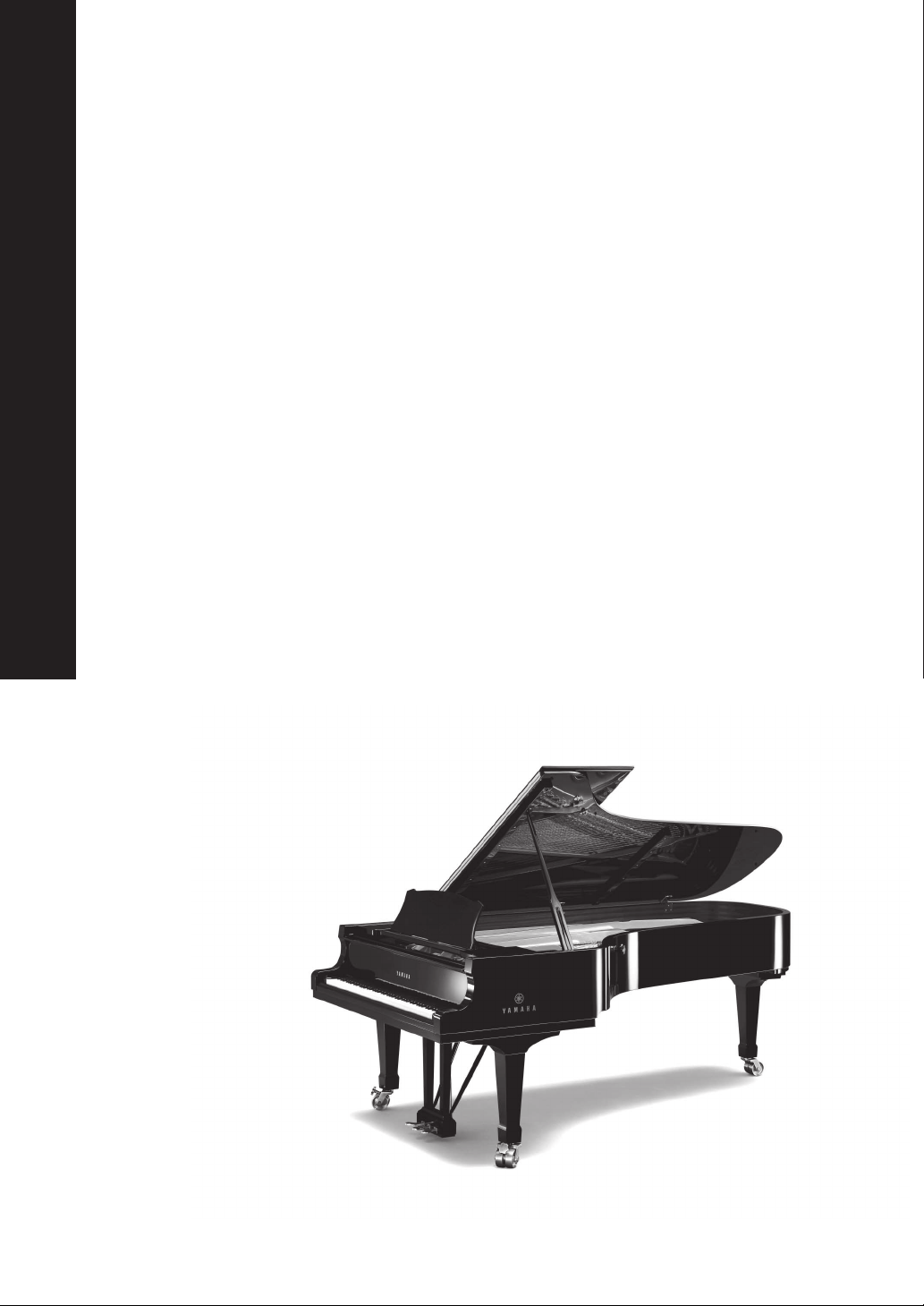
A Living Tradition in Sound
A piano comes into this world through the perfect synergy of advanced technical
skill and artistry. Such a piano can create sound that truly reflects the player’s
feelings.
The final stage in piano production is called “voicing”. It is here that the
instrument is given its soul.
A highly skilled expert concentrates his mind and sensitivity on the sound of each
key, finely adjusting the dynamic feel of the hammers, bringing the tone and
vibrancy of all 88 keys together perfectly; a truly stunning achievement.
It is a quality of sound that can only be determined by an astute, sensitive ear. We
apply this very same concept to the manufacture of our audio products. The
technician performs exhaustive listening tests and every component is considered,
in order to finally achieve the ideal sound.
Yamaha’s tradition of audio quality stretches back over 125 years, and continues to
live on in all Yamaha products today.
3 En
NP-S2000
Soavo-1
NS-10M
A-S3000
CD-S3000
NS-20
CA-1000
NS-690
B-1
PX-2
C-2
NS-1000M
A-1
B-6
B-2x
MX-10000
CX-10000
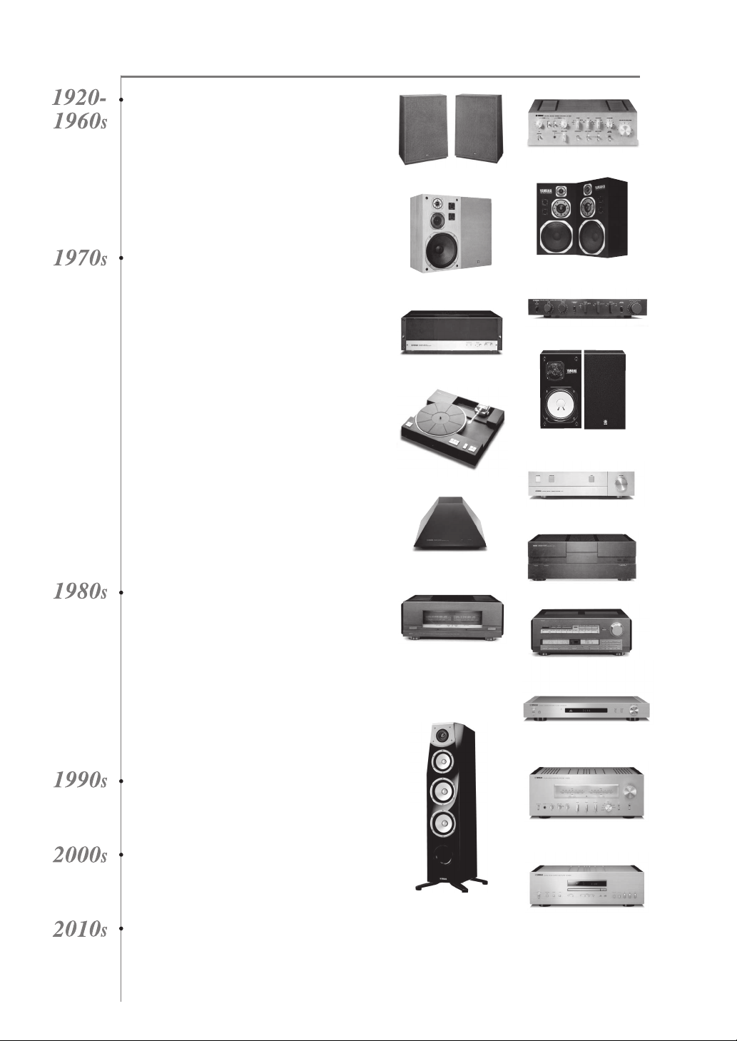
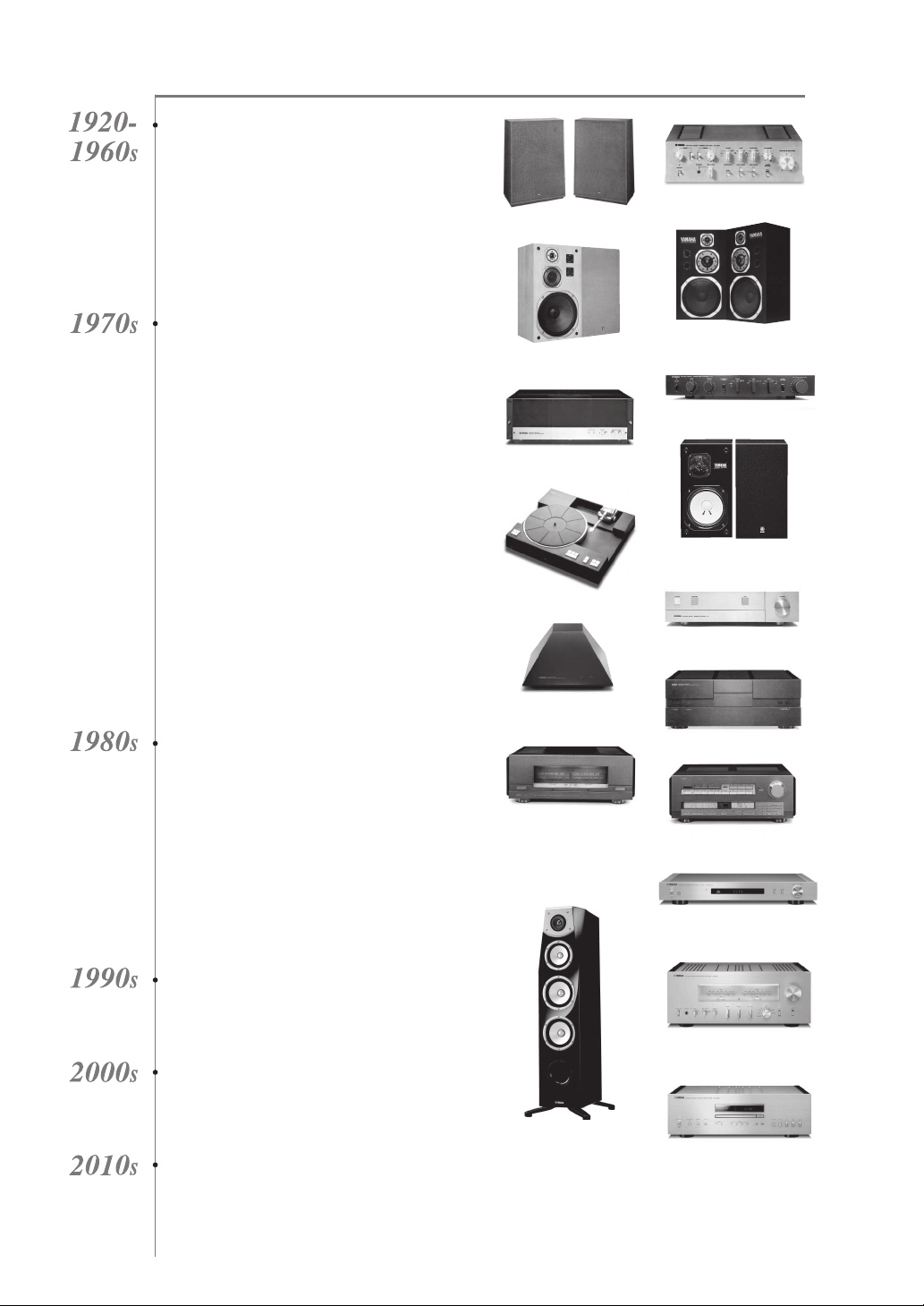
Excellence in Audio Achievement
First HiFi System introduced in 1920
We introduced numerous HiFi components
(turntables, FM/AM tuners, integrated
amplifiers, preamplifiers, power amplifiers
and speakers) in 1955 - 1965.
Natural Sound Speaker Series introduced
in 1967
NS-20 Monitor Speaker
CA-1000 Integrated Amplifier
Featuring A-Class operation, the CA-1000 set
the standard for integrated amplifiers.
NS-690 Natural Sound Speaker
NS-1000M Monitor Speaker
A truly legendary speaker still revered by HiFi
enthusiasts.
B-1 Power Amplifier
An innovative power amp that used vertical FETs in all
stages.
C-2 Control Amplifier
Received top prize at the Milan International Music
and HiFi Show.
NS-10M Studio Monitor Speaker
Became of the most popular studio monitors
in the world.
A-1 Integrated Amplifier
PX-2 Turntable
Yamaha’s first straight arm turntable.
B-6 Power Amplifier
Pyramid-shaped power amplifier.
GT-2000/L Turntable
First CD Player (CD-1) introduced in 1983
B-2x Power Amplifier
MX-10000 Power Amplifier and
CX-10000 Control Amplifier
Redefined the capabilities of separate components.
AX-1 Integrated Amplifier
GT-CD1 CD Player
MX-1 Power Amplifier and
CX-1 Preamplifier
Soavo-1 and Soavo-2 Natural Sound
Speaker Systems
A-S2000 Integrated Amplifier and
CD-S2000 CD Player
NP-S2000 Network Player
A-S3000 Integrated Amplifier and
CD-S3000 CD Player

4 En
◆ Full floating and balanced circuit design achieves the full potential of
analogue amplification
An entirely new floating and balanced power amplifier achieves complete symmetry and permits full balanced
transmission (amplification) from the input jack to just before the speaker jack.
◆ Full-stage balanced signal transmission
The integrated amplifier offers full stage balanced transmission, combining high power output with good sound texture
and outstanding S/N performance.
◆ Parallel volume and tone control
◆ Large power supply with four separate circuits
◆ Left-right symmetrical design with rigid, stable construction
◆ Discrete phono amplifier
◆ High-quality headphone amplifier with low-impedance drive
■ Supplied accessories
Please check that you have received all of the following parts.
• Remote control
• Batteries (AAA, R03, UM-4) (×2)
• Power cable
• SAFETY BROCHURE
■ About this manual
• y indicates a tip for your operation.
• Photographs and illustrations are for explanatory purposes, and may differ from the actual unit.
• Read the “SAFETY BROCHURE” before using this unit.
Contents
Controls and functions.......................................................................................................................................... 6
Connections.......................................................................................................................................................... 16
Specifications. ...................................................................................................................................................... 24
Troubleshooting................................................................................................................................................... 28
5 En
Controls and
functions
In this chapter, you will learn the controls and functions of A-S2100.

CONTROLS AND FUNCTIONS
6 En
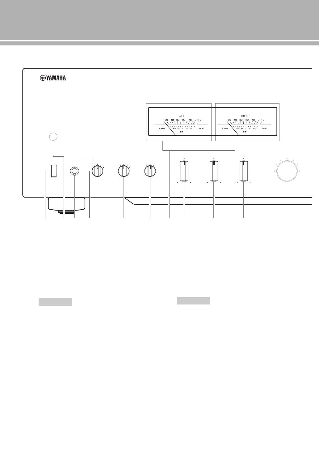
Controls and functions
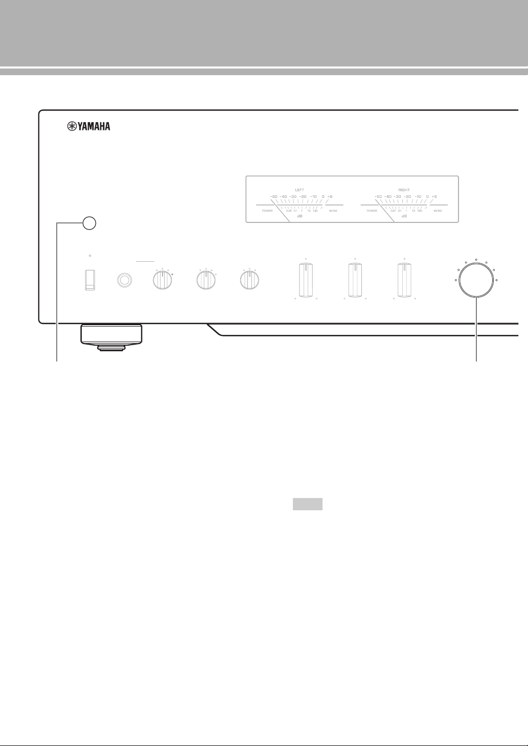
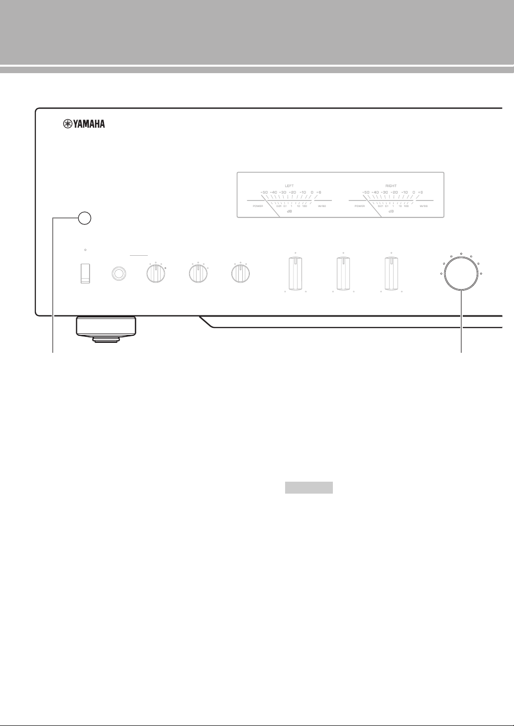
■ Front panel (pages 6 to 9)
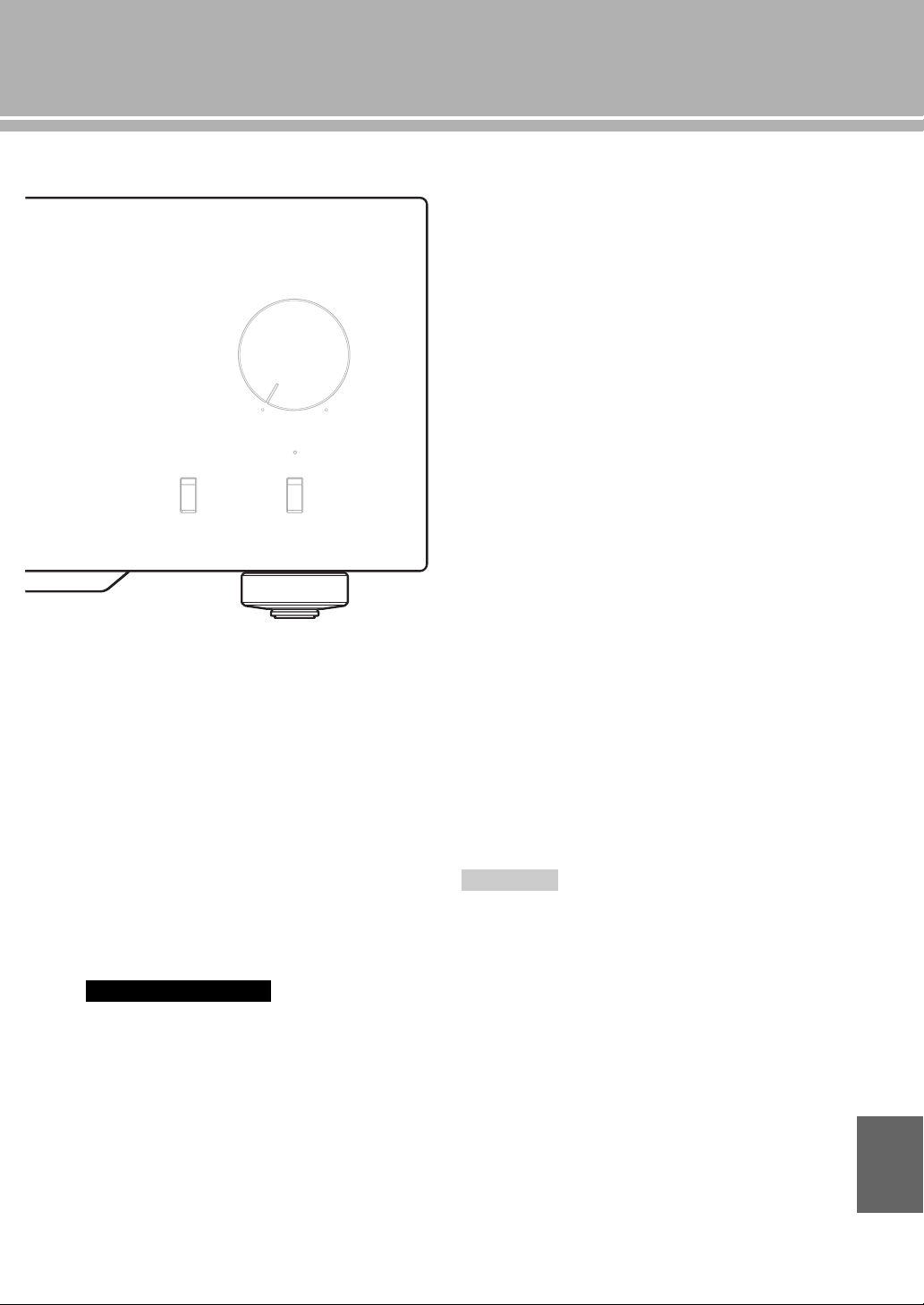
1 STANDBY/ON, OFF switch
Turns on or off this unit.
STANDBY/ON (upper position): In this position,
you can select STANDBY or ON,
using the p AMP key on the remote control.
OFF (lower position): The power of this unit is
turned off.
• When you turn on this unit, it will take a few seconds
before this unit can reproduce sound.
• If you disconnect the power cable from the AC outlet and
connect it again when this unit is in STANDBY mode, the
power of the unit is turned on. If the unit is not to be
operated for a long time, set the STANDBY/ON, OFF
switch to OFF.
2 STANDBY/ON indicator
Lit brightly: Shows that the power of the unit is ON.
In this condition, you can switch the unit to
STANDBY mode by pressing the p AMP key on
the remote control.
Lit dimly: Shows that the unit is in STANDBY mode.
In this condition, you can switch the unit on by
pressing the p AMP key on the remote control.
Off: Shows that the power of the unit is OFF. In this
condition, you can turn the power on only by
pressing the STANDBY/ON, OFF switch on the
front panel.
3 PHONES jack
Outputs audio for private listening with headphones.
• When headphones are plugged in:
– Both speaker sets connected to the SPEAKERS L/R CH
terminals are turned off.
– No signals are output at the PRE OUT jacks.
– You cannot select MAIN DIRECT as the input source.
• If headphones are plugged into the PHONES jack while
MAIN DIRECT is selected as the input source, no audio is
output at the PHONES jack.
METER
PEAK
OFF
VU
INPUT
BAL
CD
TUNER
LINE 1
PHONO
LINE 2
MAIN DIRECT
BASS
–+
TREBLE
–+
BALANCE
LR
STANDBY/ON PHONES TRIM
0
-6 +6
+12
SPEAKERS
A
OFF B
A+B
BI-WIRING
dB
OFF
1 2 3 4
5 6 7 8 9 :
Notes
Notes
7 En
4 TRIM selector
Adjusts the volume level when headphones are
plugged in to avoid sudden changes in volume.
Choices: –6 dB, 0 dB, +6 dB, +12 dB
5 SPEAKERS selector
Turns on or off the sets of speakers connected to the
SPEAKERS L/R CH A and/or B terminals on the rear
panel, as follows.
OFF: Both sets of speakers are off.
A/B: The set of speakers connected to the A or B
terminals is on.
A+B BI-WIRING: Both sets of speakers are on.
If you use two sets (A and B), the impedance of each speaker
must be 8 Ω or higher.
6 METER selector
Switches the display of the meter to OFF, PEAK or
VU.
OFF: Turns off the meter and the illumination.
PEAK: Switches the meter to a peak level meter. The
peak level meter shows a momentarily highest
audio output level.
VU: Switches the meter to a VU (Volume Unit) level
meter. The VU level meter shows an effective
audio output value that is similar to human senses.
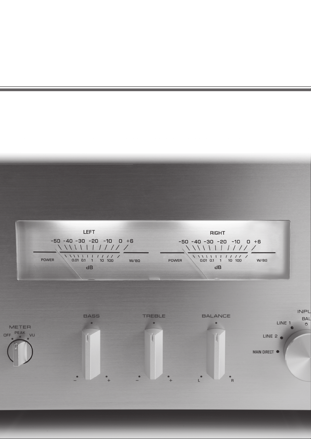
7 Meter displays (LEFT/RIGHT)
Show the audio output level of the left (LEFT) and
right (RIGHT) channels in VU or PEAK meter mode.
The VU or PEAK meter can be selected by the
METER selector.
8 BASS control
Increases or decreases the low frequency response.
The 0 position produces a flat response.
Control range: –10 dB to +10 dB
9 TREBLE control
Increases or decreases the high frequency response.
The 0 position produces a flat response.
Control range: –10 dB to +10 dB
0 BALANCE control
Adjusts the audio output balance of the left and right
speakers to compensate for sound imbalances caused
by speaker locations or listening room conditions.
• When both the BASS and TREBLE controls are set to the 0
position, audio signal bypasses the tone control circuitry.
• The BASS, TREBLE and BALANCE controls do not affect the
signals input at the MAIN IN jacks and signals output at the
LINE 2 REC jacks.
Caution
AUDIO MUTE
VOLUME
PHONO
MM
MC
Notes
English
8 En
Controls and functions
■ Front panel (pages 6 to 9)
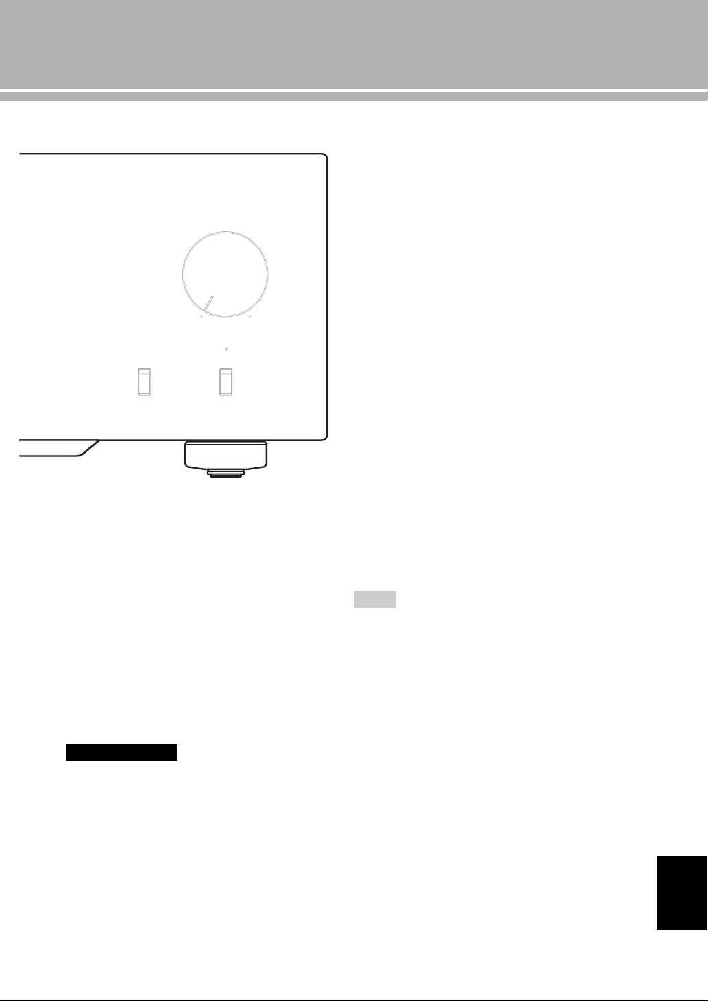
A Remote control sensor
Receives signals from the remote control.
B INPUT selector/indicator
Selects the input source to be played back. The
indicator of the input source selected with the INPUT
selector lights.
The audio signals of the selected input source are also
output at the LINE 2 REC jacks.
MAIN DIRECT: Selects the component connected to
the MAIN IN jacks.
When MAIN DIRECT is selected as the input
source, the audio signals are not output at the PRE
OUT, LINE 2 REC and PHONES jacks.
LINE 1/LINE 2: Selects the component connected to
the LINE 1 or LINE 2 jacks.
BAL: Selects the component connected to the BAL
jacks (balanced XLR jacks).
CD: Selects the CD player connected to the CD jacks
(unbalanced RCA jacks).
TUNER: Selects the tuner connected to the TUNER
jacks.
PHONO: Selects the turntable connected to the
PHONO jacks.
When LINE 2 is selected, the audio signals are not output at
the LINE 2 REC jacks.
METER
PEAK
OFF
VU
INPUT
BAL
CD
TUNER
LINE 1
PHONO
LINE 2
MAIN DIRECT
BASS
–+
TREBLE
–+
BALANCE
LR
STANDBY/ON PHONES TRIM
0
-6 +6
+12
SPEAKERS
A
OFF B
A+B
BI-WIRING
dB
OFF
A B
Note

9 En
C PHONO switch
Selects the type of cartridge of the turntable connected
to the PHONO jacks on the rear panel.
MM: Choose this setting if the connected turntable
uses an moving magnet (MM) cartridge.
MC: Choose this setting if the connected turntable
uses an moving coil (MC) cartridge.
y
When you replace the cartridge, be sure to turn off this unit.
D AUDIO MUTE switch
Press downward to reduce the current volume level by
approximately 20 dB. Press again to restore the audio
output to the previous volume level.
y
You can also rotate the VOLUME control on the front panel
or press the VOLUME + or – key on the remote control to
resume the audio output.
E AUDIO MUTE indicator
Lights when the mute function is turned on with the
AUDIO MUTE switch.
F VOLUME control
Controls the volume level. This does not affect the
output level at the LINE 2 REC jacks.
The VOLUME control does not affect when you select
MAIN DIRECT as the input source. Adjust the volume level
using the volume control on the external amplifier connected
to the MAIN IN jacks.
AUDIO MUTE
VOLUME
PHONO
MM
MC
C
D E
F
Note
English

10 En
Controls and functions
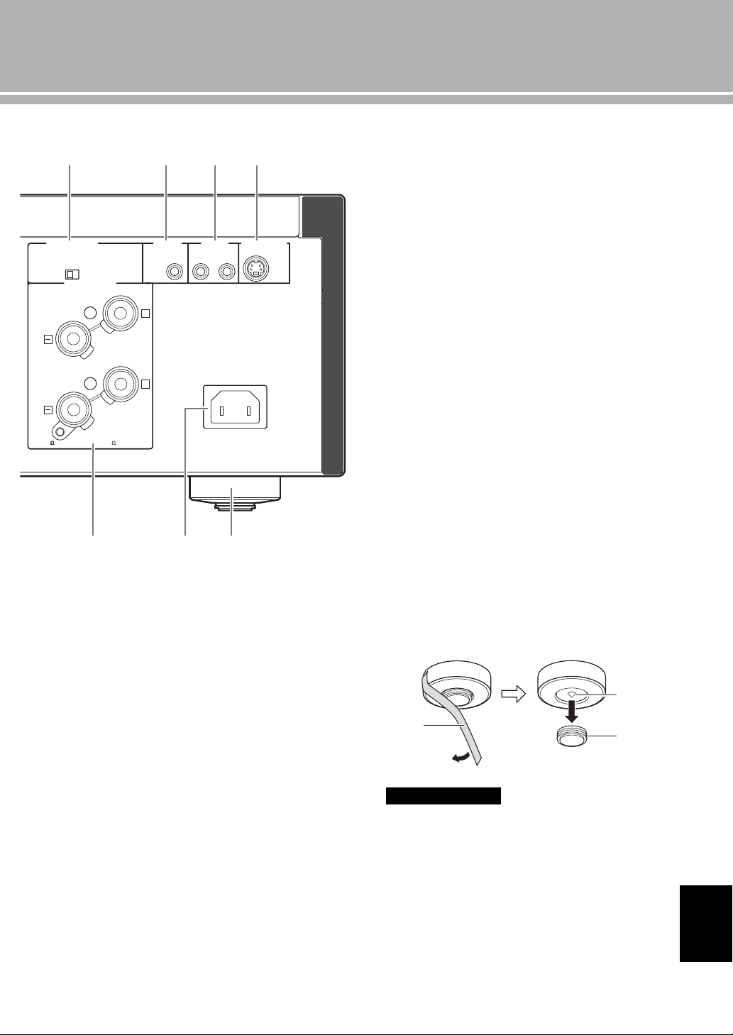
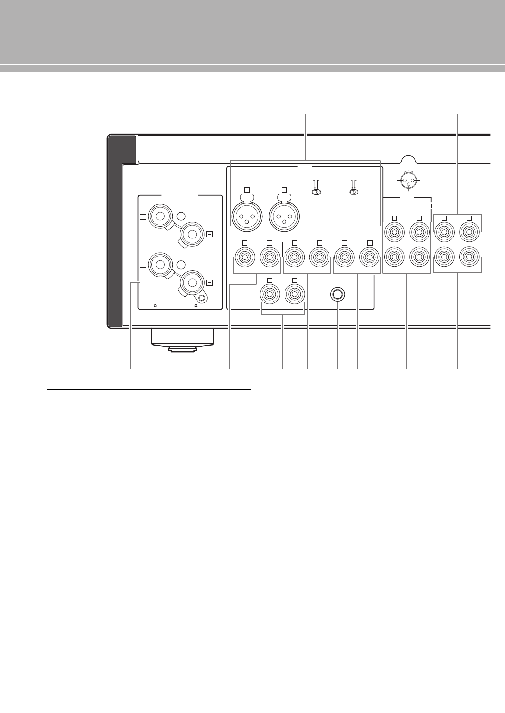
■ Rear panel
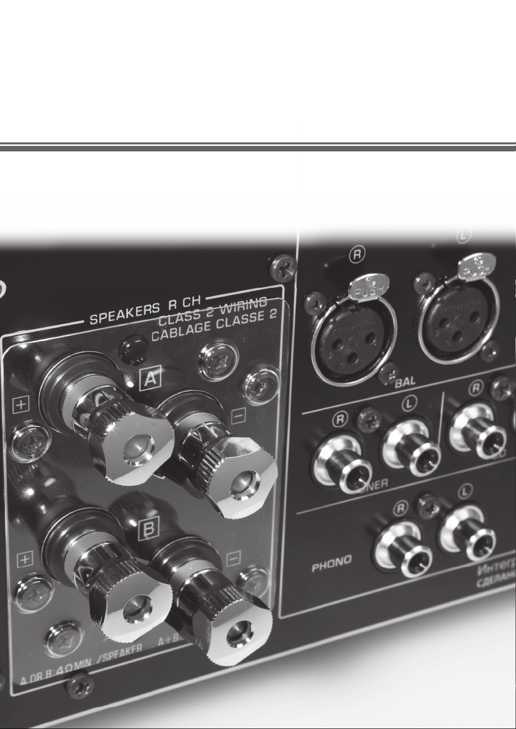
1 BAL (balanced) input jacks
One set of balanced input jacks is provided.
Set the ATTENUATOR selector and PHASE selector
appropriately for the playback component that is
connected. For details on these switches, refer to page 20.
2 PRE OUT jacks
y
• The PRE OUT jacks output the same channel signal as the
SPEAKERS L/R CH terminals.
• When you connect a stereo cable to the PRE OUT jacks to
drive the speakers using an external amplifier, it is not
necessary to use the SPEAKERS L/R CH terminals.
• The signal output at the PRE OUT jacks are affected by the
BASS and TREBLE control settings.
3 SPEAKERS L/R CH terminals
4 TUNER input jacks
5 PHONO input jacks
6 CD input jacks
7 GND (Ground) terminal
8 LINE 1 input jacks
9 LINE 2 jacks
PB (playback) input jacks and REC (recording) output
jacks are provided.
0 MAIN IN jacks
Use these jacks to connect an external component
equipped with a volume control.
y
When you select MAIN DIRECT as the input source, the
volume level is fixed.
Adjust the volume level using the volume control on the
external amplifier connected to the MAIN IN jacks when you
select MAIN DIRECT as the input source.
For the connection to the
MAIN IN
jacks, see pages 16 and 17.
GND
PHONO
LINE 1
CD
BAL
(-6dB)
ATT. INV.
BYPASS NORMAL
PHASE
ATTENUATOR
INPUT
SPEAKERS R CH
A
B
+
+
A OR B:4 MIN. /SPEAKER
A+B:8 MIN. /SPEAKER
R L
R R
R
L
TUNER
LINE2
REC
PB
MAIN IN
L
L
L
R
R R
L
L
PRE OUT
NORMAL (EIA)
+ HOT
- COLD
GND
12
3
1 2
3 4
5 6 7 8 9 0
See page 16 for connection information.
11 En
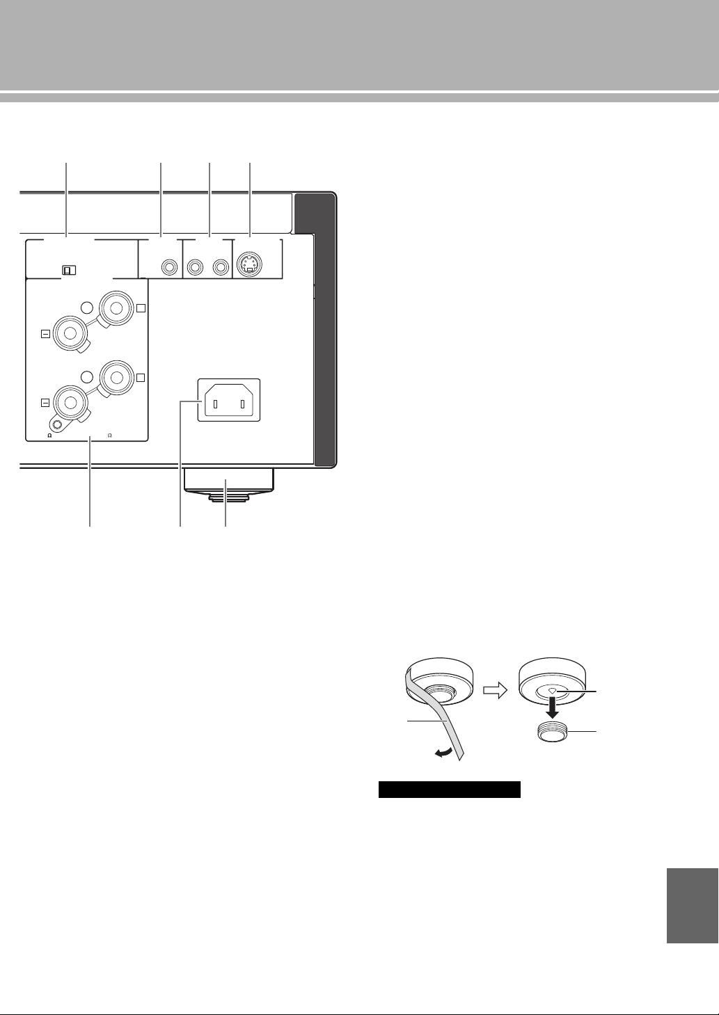
A AUTO POWER STANDBY switch
ON: The unit enters STANDBY mode automatically
if not operated for 8 hours.
OFF: The unit does not enter STANDBY mode
automatically.
B TRIGGER IN jack
Use this jack to connect an external component for the
trigger function.
For details on the connection, see page 22.
C REMOTE IN/OUT jacks
Use these jacks to connect an external component for
remote control.
For details on the connection, see page 21.
D SYSTEM CONNECTOR
Use this connector to connect a product testing device
for servicing.
E AC IN inlet
Use this inlet to plug in the supplied power cable.
For details on the connection, see page 19.
F Foot
The feet of this unit include built-in spikes. Using the
spikes can reduce the effect of vibrations on the set.
When using the spikes, remove the transport tape, then
remove the magnet foot by pulling it.
• Take care that the magnet foot is not accidentally
swallowed by small children.
• When using the feet’s built-in spikes, the spikes may
scratch the shelf or floor on which this unit is installed. Use
the magnet feet or appropriate supports when placing this
unit on expensive furniture, etc.
y
If this unit is unstable, you can adjust the foot height by
rotating it.
AUTO POWER STANDBY
ON
OFF
SPEAKERS L CH
A
B
+
+
TRIGGER
REMOTE
SYSTEM CONNECTOR
IN IN OUT
AC IN
A OR B:4 MIN. /SPEAKER
A+B:8 MIN. /SPEAKE
R
A B C D
E
3 F
Caution
Spike
Transport
tape
Magnet
foot
English
12 En
Controls and functions
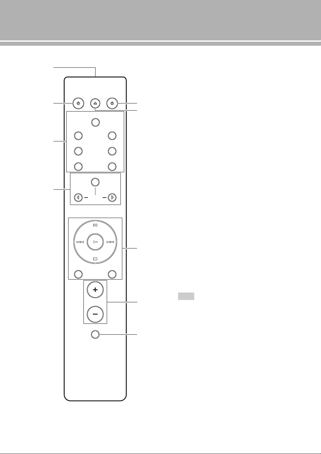
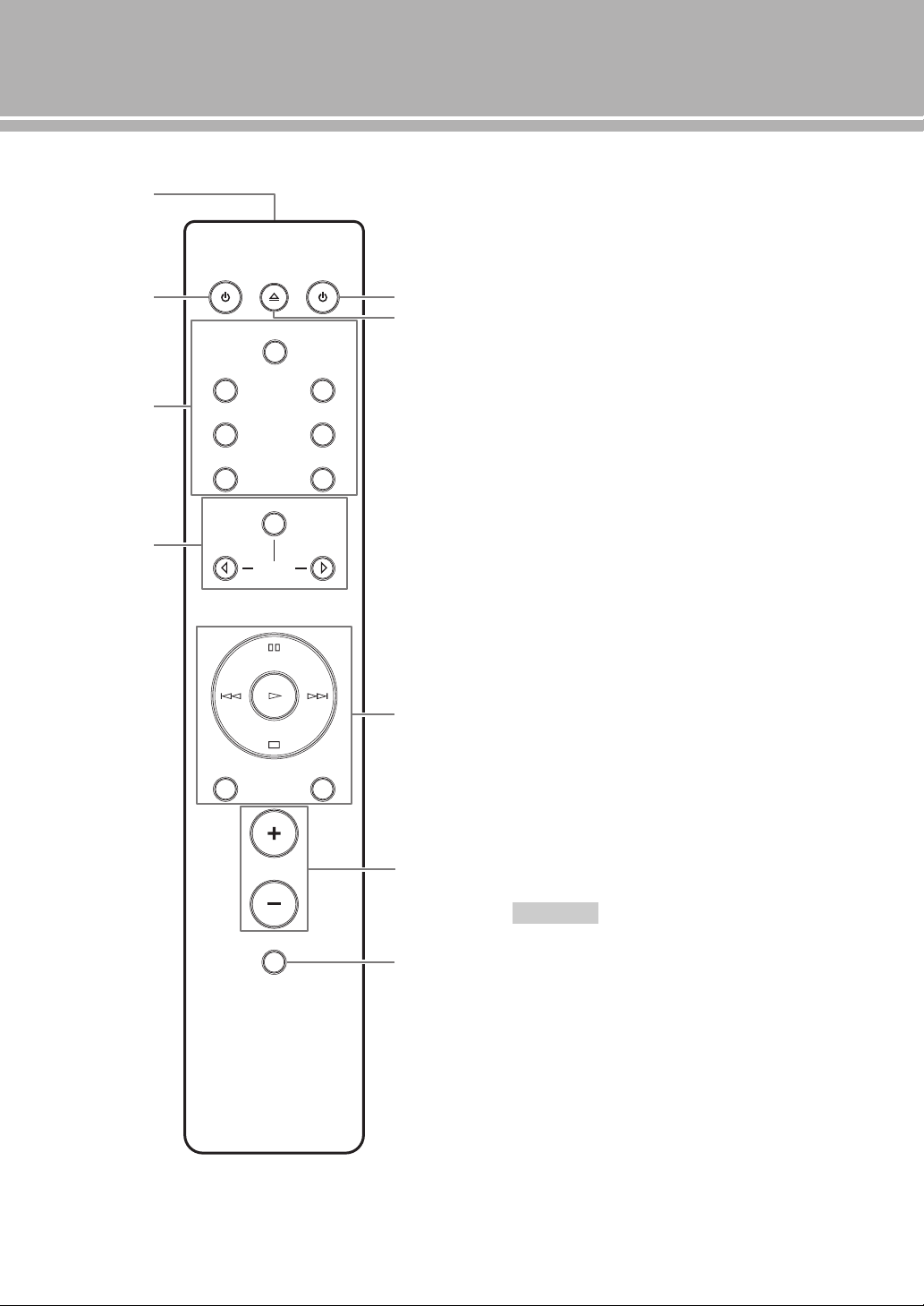
■ Remote control
1 Infrared signal transmitter
Outputs infrared control signals.
2 p AMP key
Turns this unit ON or switches it to STANDBY mode.
For details on STANDBY mode, see “Front panel”
(page 6).
3 Input select keys
Selects the input source to be played back.
The audio signals of the selected input source are
output at the LINE 2 REC jacks.
y
When LINE 2 is selected as the input source, the audio
signals are not output at the LINE 2 REC jacks.
BAL: Selects the component connected to the BAL
jacks (balanced XLR jacks).
LINE: Selects the component connected to the
LINE 1 or LINE 2 jacks.
PHONO: Selects the turntable connected to the
PHONO jacks.
MAIN DIRECT: Selects the component connected to
the MAIN IN jacks. When MAIN DIRECT is
selected as the input source, the audio signals are
not output at the PRE OUT, LINE 2 REC and
PHONES jacks.
CD: Selects the CD player connected to the CD jacks
(unbalanced RCA jacks).
TUNER: Selects the tuner connected to the TUNER
jacks
4 Yamaha tuner control buttons
Control functions of Yamaha tuner. Refer to the
owner’s manual of your tuner for details.
Some Yamaha tuners cannot be controlled by this remote
control.
4
2
1
3
8
9
5
7
6
AMP CD
OPEN/CLOSE
BAL
LINE LINE
PRESET
12
PHONO
MAIN DIRECT
CD TUNER
BAND
MUTE
SOURCE LAYER
VOLUME
Note

13 En
5 p CD key
Turns the Yamaha CD player ON or switches it to
STANDBY mode.
6 OPEN/CLOSE key
Opens/closes the disc tray of the Yamaha CD player.
Refer to the owner’s manual of your CD player for
details.
Some Yamaha CD players do not support the p CD key and/
or OPEN/CLOSE key of this remote control.
7 Yamaha CD player control keys
Control various functions of Yamaha CD player. Refer
to the owner’s manual of your CD player for details.
(Play): Starts playback.
(Pause): Pauses playback. Press the or to
resume playback.
(Stop): Stops playback.
/ (Skip): Skips to the next track, or skips
back to the beginning of the current track.
SOURCE: Selects the source to be played on the
Yamaha CD player. The playback source changes
each time this key is pressed.
LAYER: Switches the playback layer of a hybrid SA-
CD between SA-CD and CD.
8 VOLUME +/– keys
Control the volume level.
The VOLUME keys do not affect when you select MAIN
DIRECT as the input source. Adjust the volume level on the
external amplifier connected to the MAIN IN jacks.
9 MUTE key
Reduces the current volume level by approximately
20 dB. Press again to restore the audio output to the
previous volume level. Pressing the VOLUME + or –
key also cancels muting.
Note
Note
English
14 En
Controls and functions
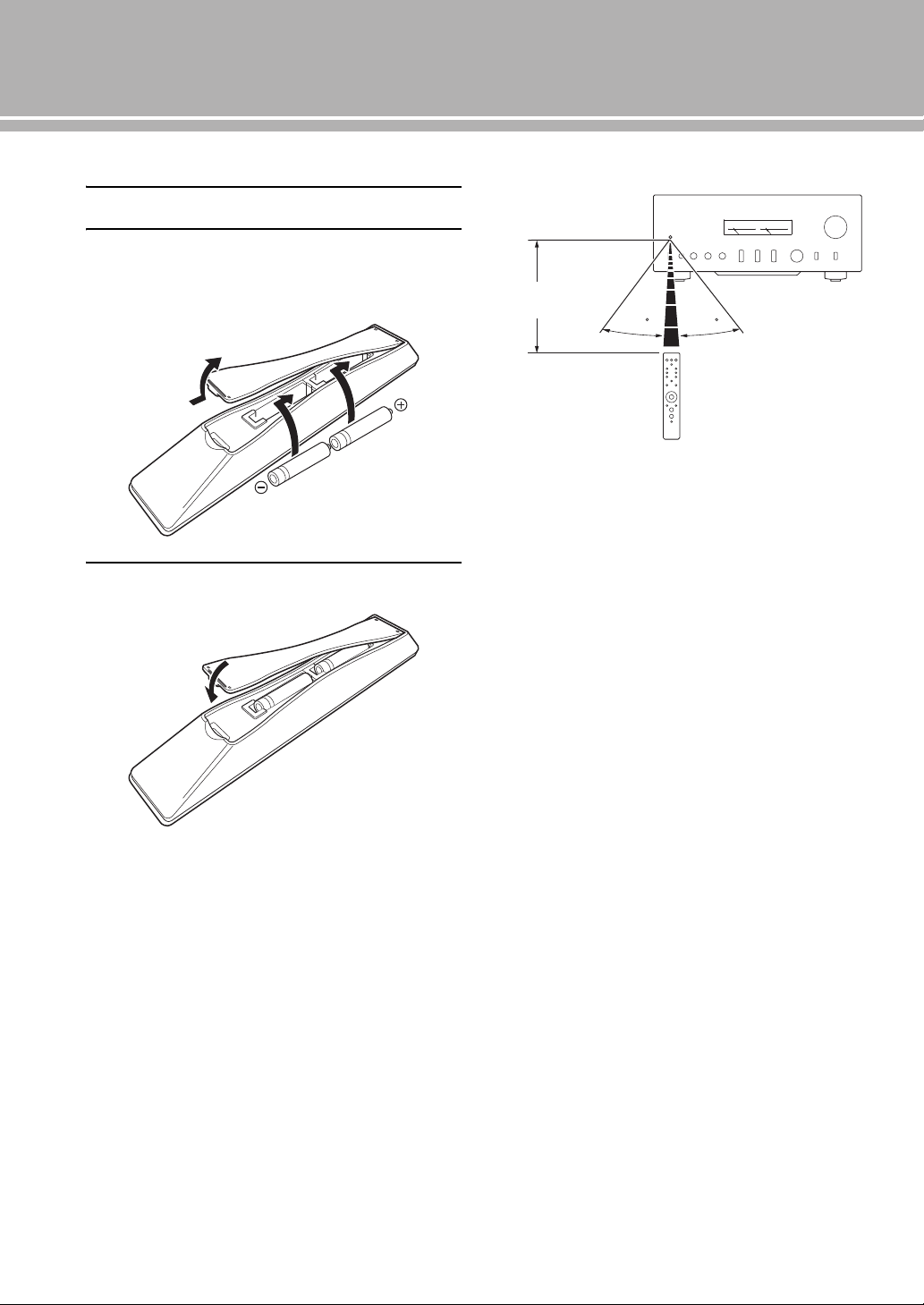
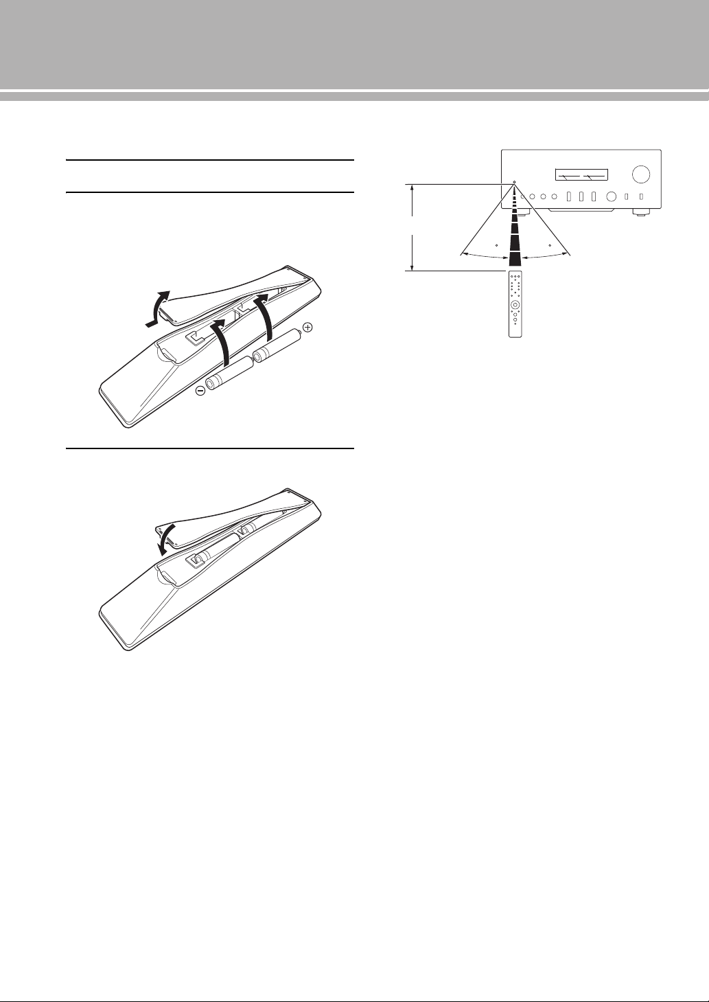
■ Installing batteries in the remote control
1 Remove the battery compartment cover.
2 Insert the two batteries (AAA, R03, UM-4)
according to the polarity markings (+ and –)
on the inside of the battery compartment.
3 Reinstall the battery compartment cover.
■ Operating range of the remote control
y
The remote control transmits a directional infrared beam. Be
sure to aim the remote control directly at the remote control
sensor on the front panel of this unit during operation.
2
1
3
30 30
Approximately 6 m
(20 ft)
Connections
In this section, you will make connections between A-S2100, speakers,
and source components.
16 En
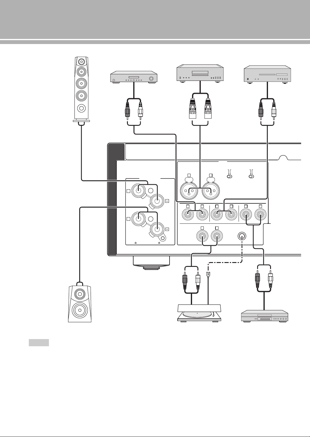
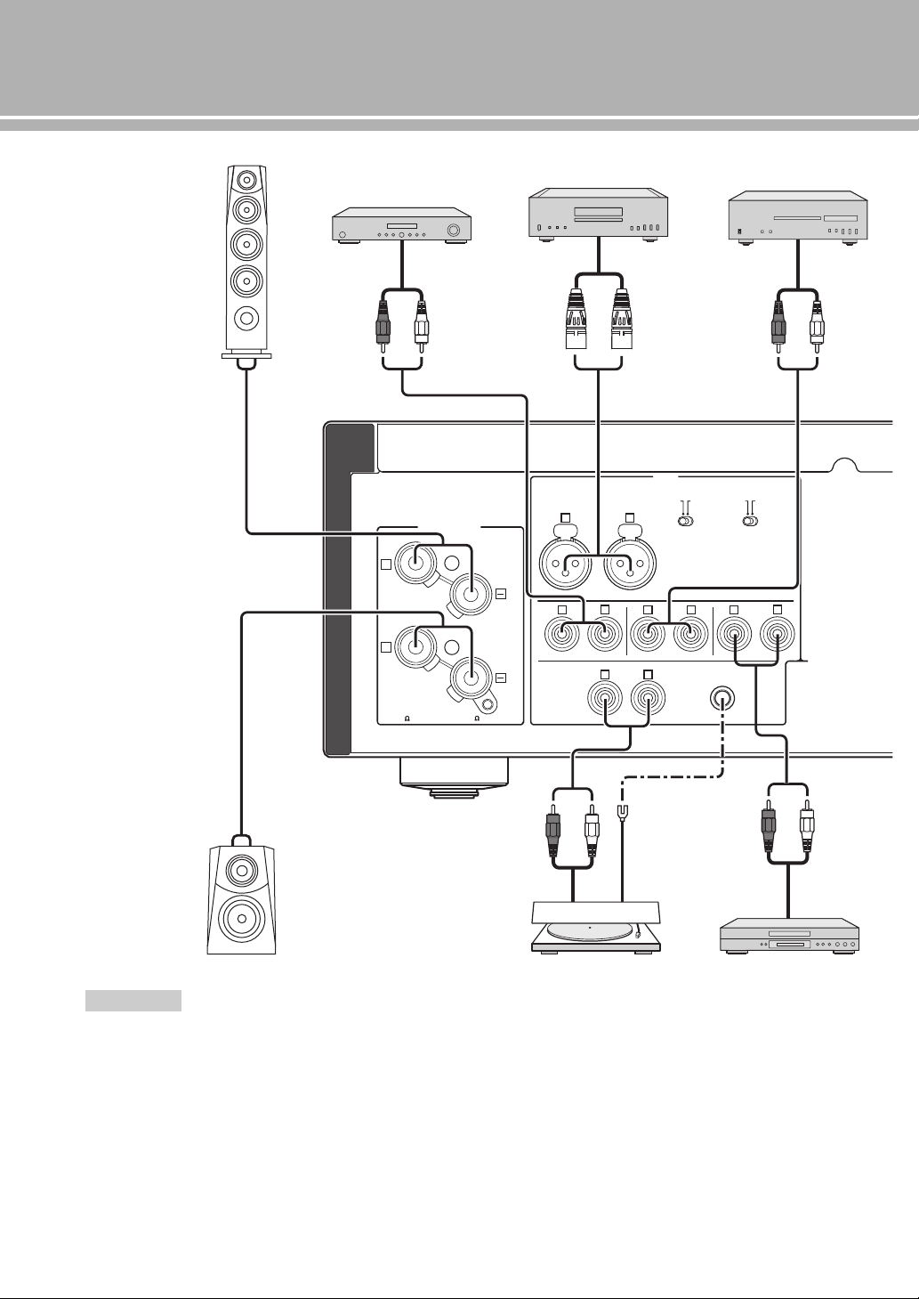
Connections
• Do not let the bare speaker wires touch each other or do not let
them touch any metal part of this unit. This could damage this
unit and/or the speakers.
• All connections must be correct: L (left) to L, R (right) to R,
“+” to “+”, and “–” to “–”. If the connections are faulty, no
sound will be heard from the speakers, and if the polarity of the
speaker connections is incorrect, the sound will be unnatural
and lack bass. Also, refer to the owner’s manual for each of
your components.
• Use RCA unbalanced cables to connect other components
except speakers. Use XLR balanced cables to connect a CD
player or network player with XLR balanced output jacks to the
BAL jacks of this unit.
• Connect your turntable to the GND terminal to reduce noise in
the signal. However, you may hear less noise without the
connection to the GND terminal for some turntables.
Notes
GND
PHONO
LINE1
CD
BAL
(-6dB)
ATT. INV.
BYPASS NORMAL
PHASE
ATTENUATOR
INPUT
SPEAKERS R CH
A
B
+
+
A OR B:4 MIN. /SPEAKER
A+B:8 MIN. /SPEAKER
R L
R R
R
L
TUNER
L
L
L
R
+
-
+
-
CD player with
RCA jacks
Speakers A
(R channel)
Speakers B
(R channel)
CD player or network
player with XLR jacks
Turntable
Ground
Tuner
BD player, etc.
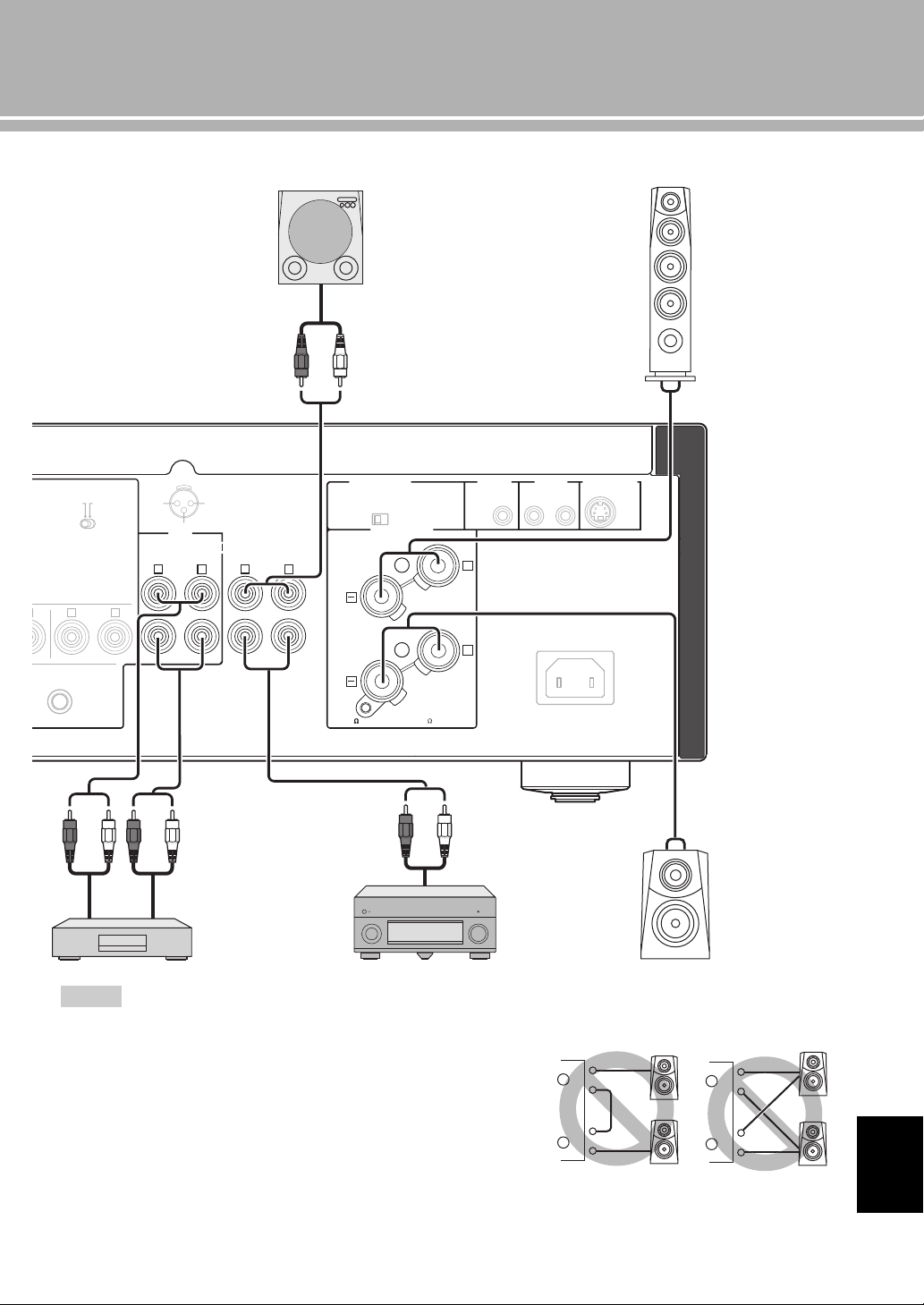
17 En
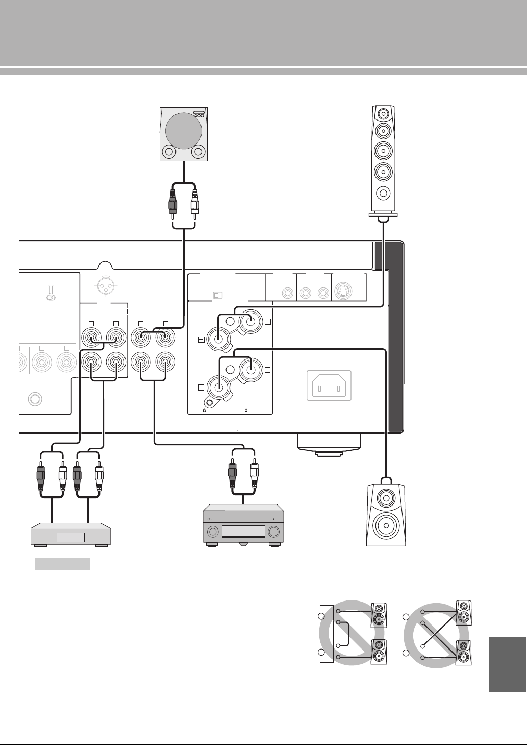
• Because the power amplifier of A-S2100 is of the floating balanced type, the
following types of connections are not possible.
– Connecting with the left channel “–” terminal and the right channel “–” terminal
as well as “+” terminals (Fig. 1).
– Connecting with the left channel “–” terminal and the right channel “–” terminal
inverted (cross connection, Fig. 2).
– Deliberately connecting with the left/right channel “–” terminals and metal part
on the rear panel of this unit, as well as accidentally touching them.
• Do not connect your active subwoofer to the SPEAKERS L/R CH terminal.
Connect it to the PRE OUT jacks of this unit.
• Do not connect a component with no volume control, such as a CD player, to the
MAIN IN jacks, as the volume level of the signals input to the MAIN IN jacks is
fixed. If such equipment is connected, a sound may burst, and the unit and/or
speaker may be damaged.
Notes
GND
LINE 1
-6dB)
TT. INV.
NORMAL
PHASE
TOR
LINE2
REC
PB
MAIN IN
L
R
R R
L
L
NORMAL (EIA)
+ HOT
- COLD
GND
12
3
PRE OUT
AUTO POWER STANDBY
ON
OFF
SPEAKERS L CH
A
B
+
+
TRIGGER
REMOTE
SYSTEM CONNECTOR
IN IN OUT
AC IN
A OR B:4 MIN. /SPEAKER
A+B:8 MIN. /SPEAKER
+–
+
-
CD recorder,
tape deck, etc.
Speakers A
(L channel)
Speakers B
(L channel)
External amplifier or
active subwoofer
Preamplifier,
AV receiver, etc.
English
+
–
+
–
L
R
+
–
+
–
L
R
+
–
+
–
L
R
+
–
+
–
L
R
Fig. 1 Fig. 2
18 En
Connections
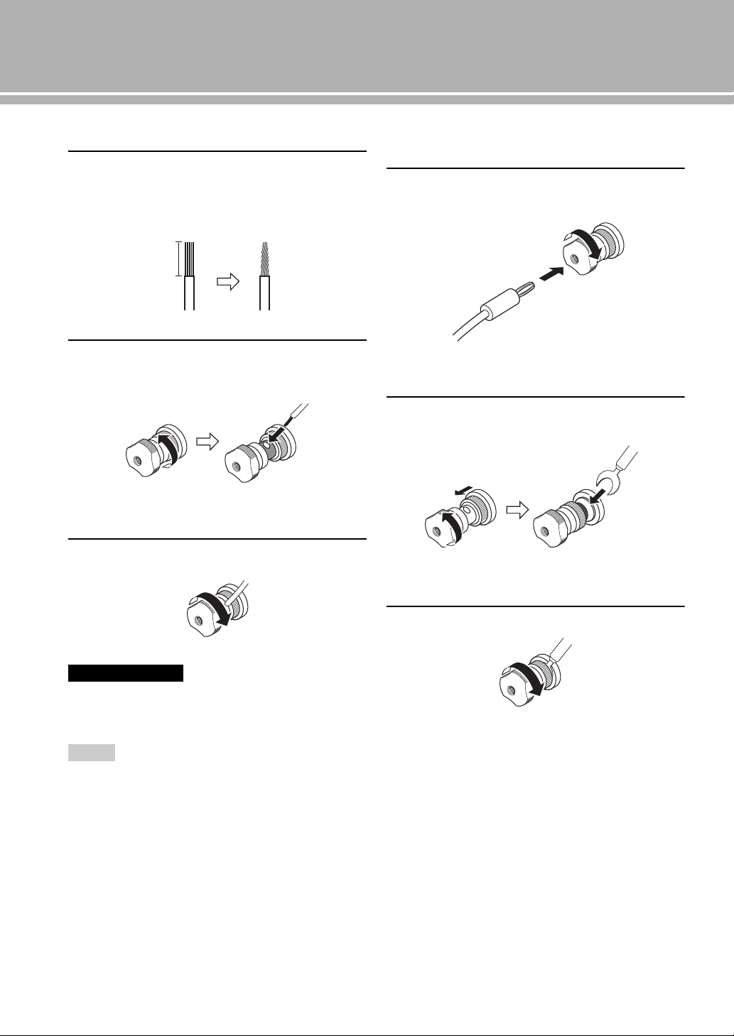
■ Connecting the speakers
1 Remove approximately 10 mm of insulation
from the end of each speaker cable and twist
the exposed wires of the cable together to
prevent short circuits.
2 Unscrew the knob and then insert the bare
wire into the hole.
3 Tighten the knob.
When loosening the knob of the speaker terminal, do not rotate it
excessively. The knob may come off and pose the danger of being
swallowed by a child.
• Touching the speaker terminal with a metallic rack may cause
short circuit and damage this unit. When installing the unit in a
rack, maintain a sufficient clearance to prevent the speaker
terminals from touching the rack.
• To reduce the risk of electric shock, do not touch the speaker
terminal when the unit is turned on.
■ Connecting the banana plug
(Except for Europe models)
First, tighten the knob and then insert the banana
plug into the end of the corresponding terminal.
■ Connecting the Y-shaped lug
1 Unscrew the knob and then sandwich the Y-
shaped lug between the ring part and base.
2 Tighten the knob.
Caution
Notes
10 mm
Hole for speaker cable:
6.0 mm dia.
Banana plug
Hole for banana plug:
3.95 mm dia.
Y-shaped lug
Slide
Terminal screw for Y-shaped
lug: 5.8 mm dia.
19 En
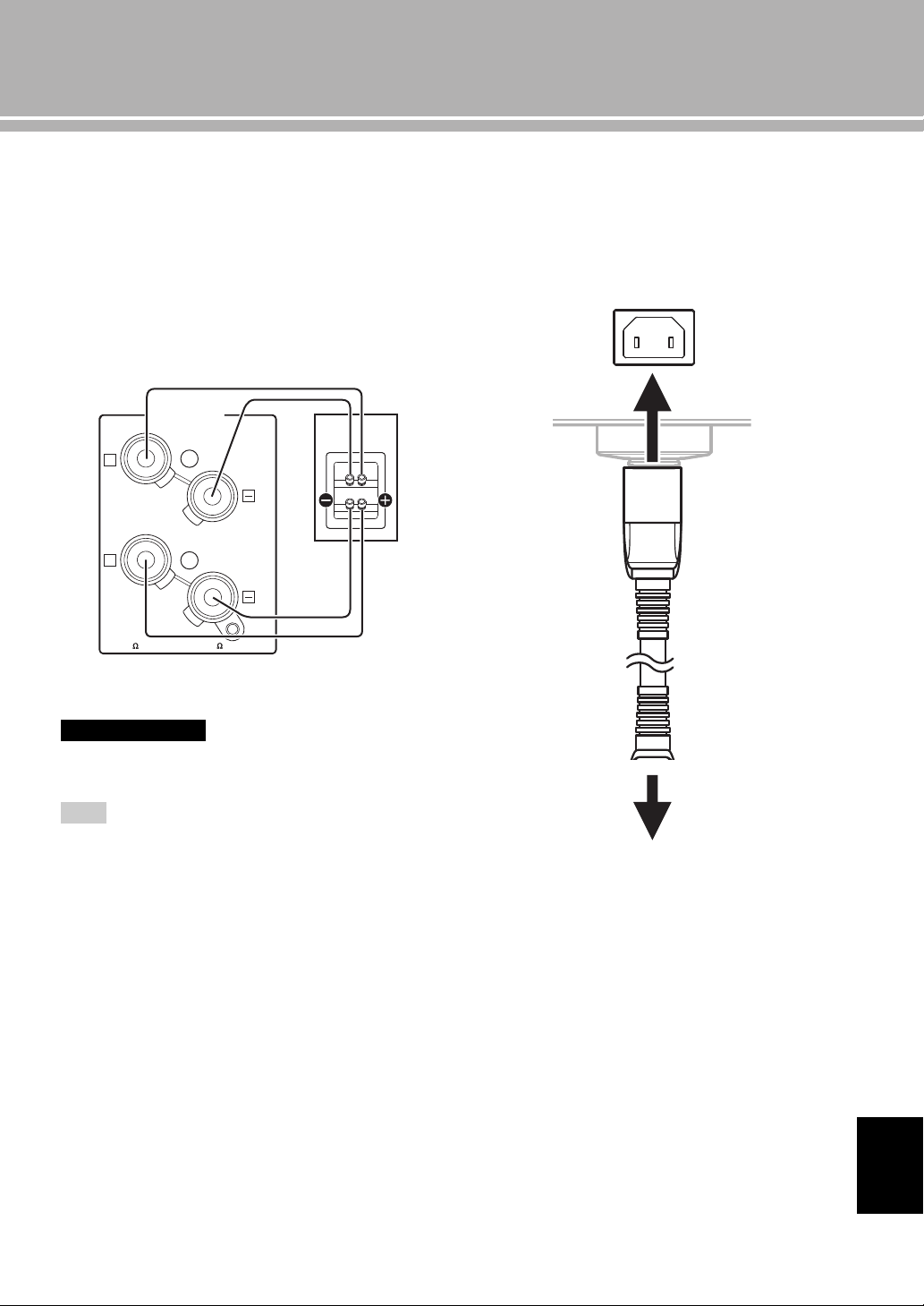
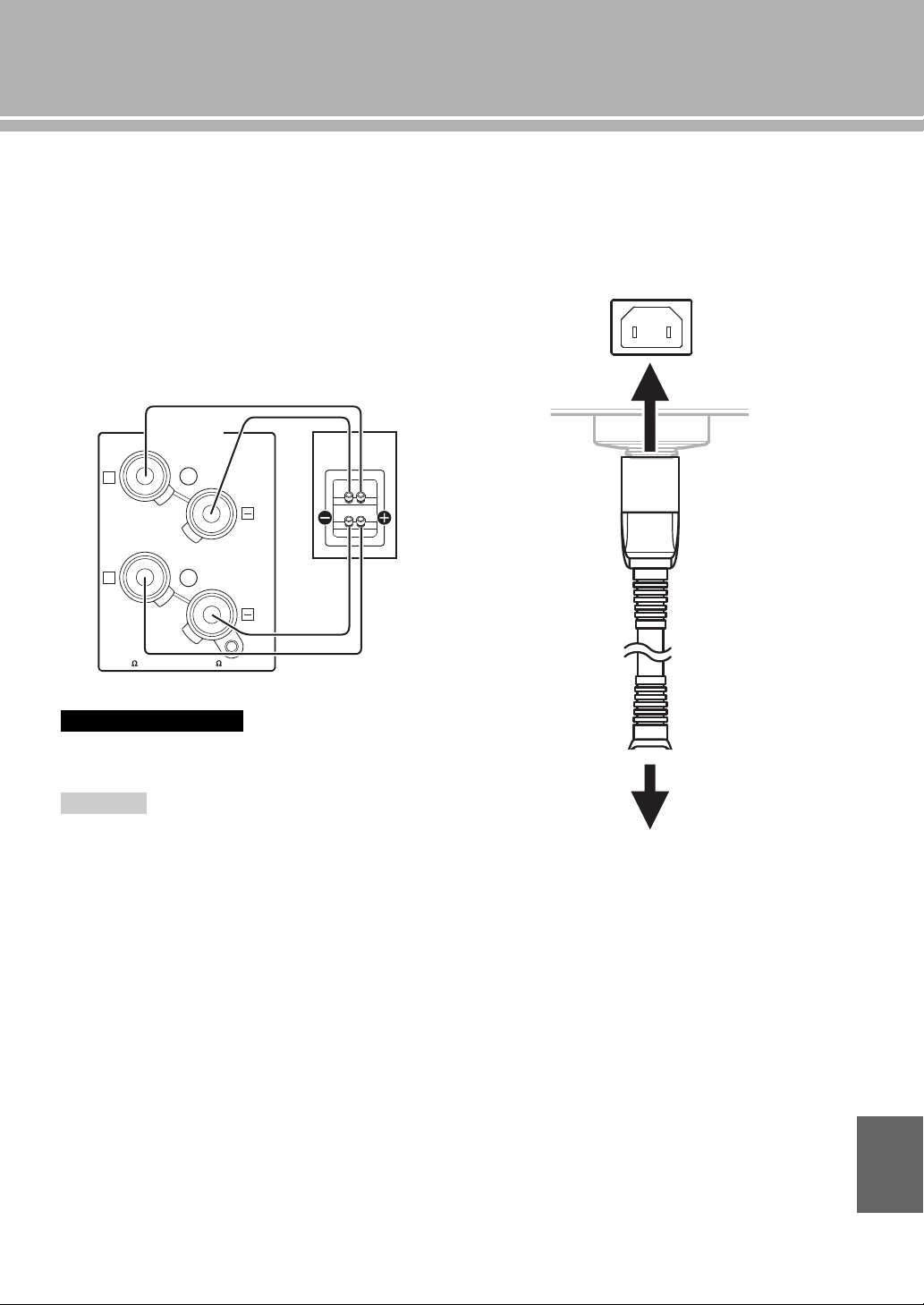
■ Bi-wire connection
The bi-wire connection separates the woofer from the
combined midrange and tweeter section. A bi-wire
compatible speaker has four binding post terminals. These
two sets of terminals allow the speaker to be split into two
independent sections. This split connects the mid and high
frequency drivers to one set of terminals and the low
frequency driver to the other pair.
Example of a bi-wiring connection (R channel)
To use the bi-wire connections, the impedance of each speaker
must be 8 Ω or higher.
Remove the shorting bars or bridges to separate the LPF (low
pass filter) and HPF (high pass filter) crossovers.
y
To use the bi-wire connections, switch the SPEAKERS selector
on the front panel to the A+B BI-WIRING position.
■ Connecting the power cable
Plug the power cable into the AC IN inlet when all
connections are complete, and then plug in the power
cable to the AC outlet.
Caution
Note
SPEAKERS R CH
A
B
+
+
A OR B:4 MIN. /SPEAKER
A+B:8 MIN. /SPEAKER
Rear panel of A-S2100 Speaker
AC IN
to an AC outlet
Rear panel of A-S2100
Supplied power cable
English
20 En
Connections
■ Connecting to the BAL jacks
Connect your CD player or network player with the XLR
balanced output jacks.
Set the ATTENUATOR selector and PHASE selector
located above the BAL
jacks according to the component
to be connected.
ATTENUATOR selector:
Select the allowable input level for the XLR balanced
input jacks. If sound from the connected component is
distorted, set the ATTENUATOR selector to ATT. (-6 dB).
PHASE selector:
Select the assignment of the HOT pin of the XLR
balanced input jacks (pin 2 HOT or pin 3 HOT).
NORMAL (pin 2 HOT)
INV. (pin 3 HOT)
Refer to the owner’s manual supplied with the connected
component and verify the assignment of the HOT pin of
its XLR balanced output jacks.
y
Yamaha CD players are set to NORMAL (pin 2 HOT).
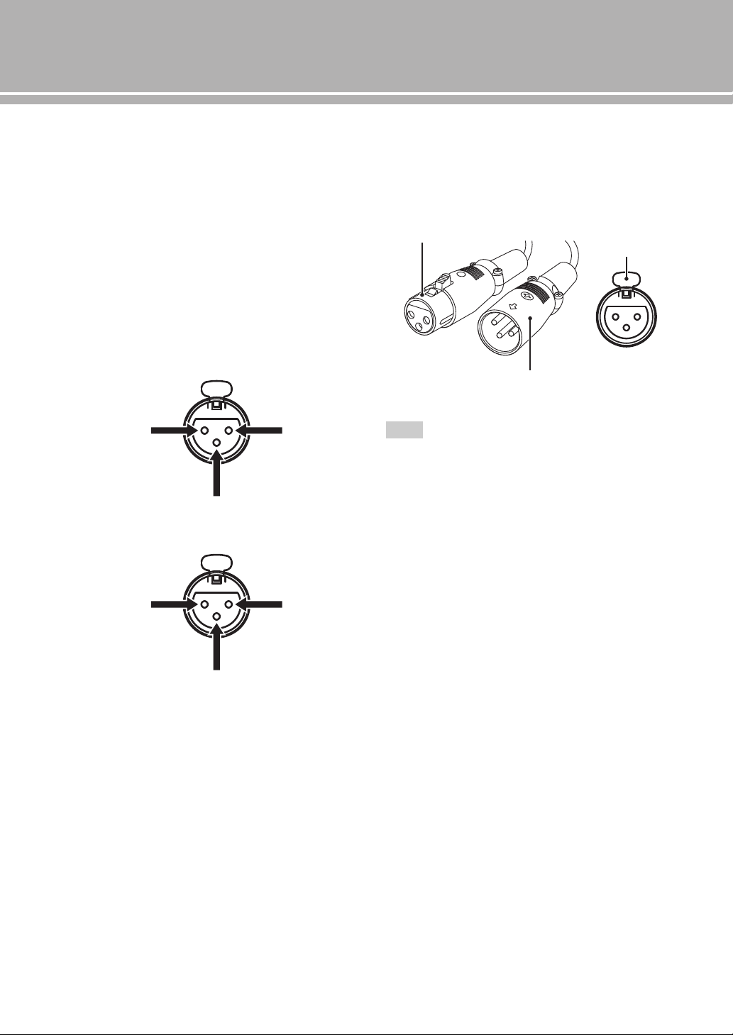
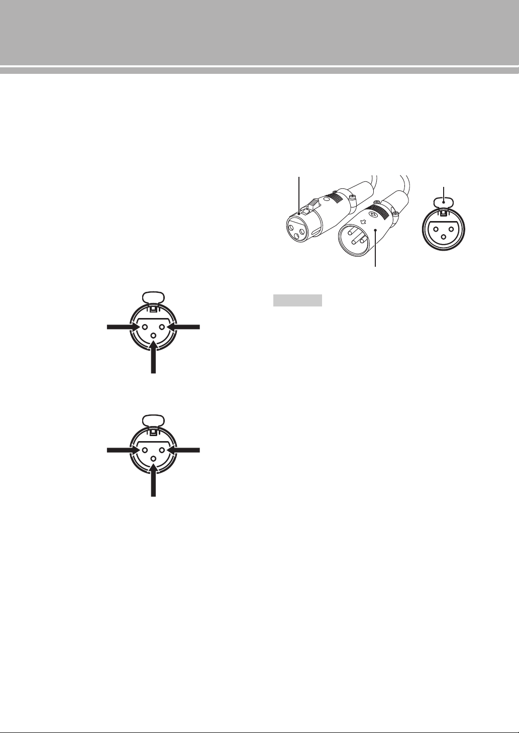
XLR connectors:
When connecting, be sure to match the pins and insert the
connector of the “male” XLR balanced cable until you
hear a “click”. When disconnecting, pull out the “male”
XLR balanced cable while holding down the lever of the
BAL jack.
To select the component connected to the BAL jacks, set the input
source to BAL.
1: ground2: hot
3: cold
1: ground2: cold
3: hot
Note
“Female” XLR connector
“Male” XLR connector
Lever
BAL jack
21 En
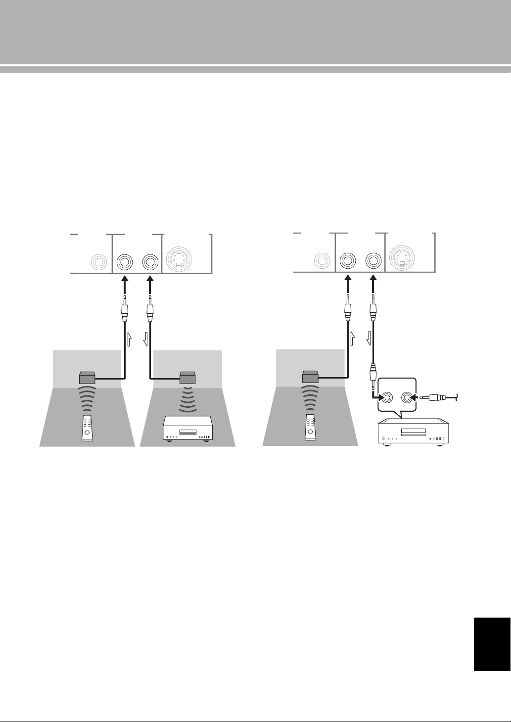
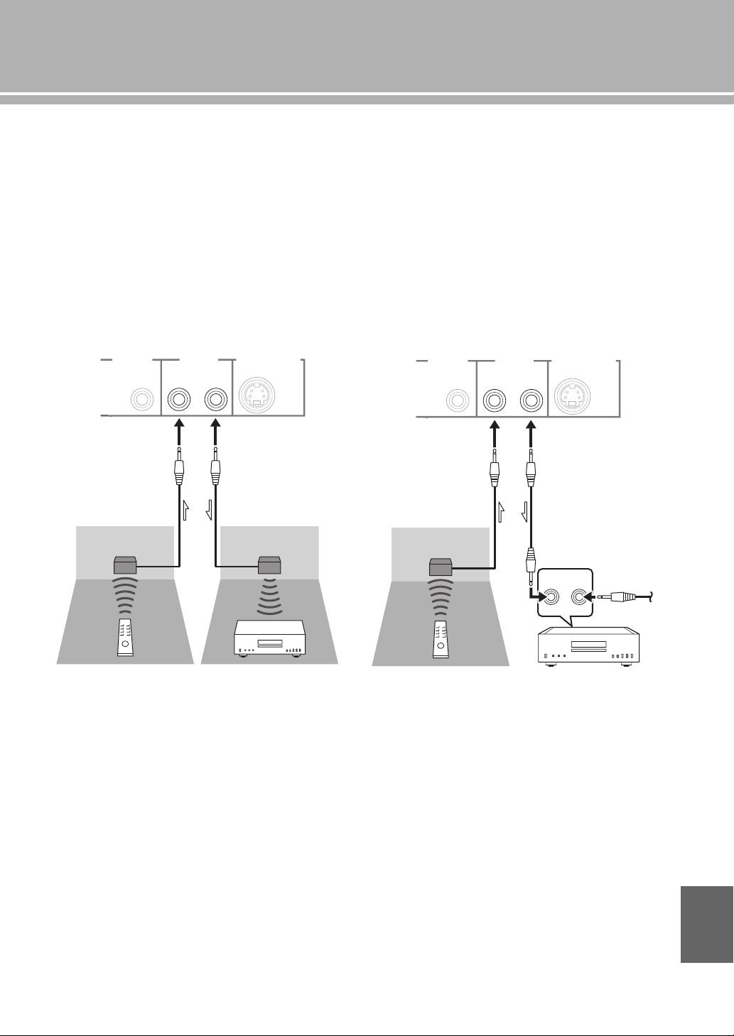
■ Operating this unit from another room
If you connect an infrared receiver and transmitter to the
REMOTE IN/OUT jacks of this unit, you can operate the
unit and/or external component using the supplied remote
control located in another room.
■ Remote connection between Yamaha
components
When you have another Yamaha component supporting
remote connection, as this unit does, an infrared
transmitter is not necessary. You can transmit remote
signals by connecting an infrared receiver and the
REMOTE IN jack of the other component to the
REMOTE IN/OUT jacks of this unit, using cables with
monaural miniplugs.
Up to three Yamaha components (including this unit) can
be connected.
TRIGGER
REMOTE
SYSTEM CONNECTOR
IN IN OUT
Rear panel of A-S2100
Infrared receiver
Remote control
Infrared transmitter
External component
(CD player, etc.)
TRIGGER
REMOTE
SYSTEM CONNECTOR
IN IN OUT
REMOTE
IN OUT
Rear panel of A-S2100
Infrared receiver
Remote control Yamaha component
(up to three
components
including this unit)
Monaural mini-plug
cable
English
22 En
Connections
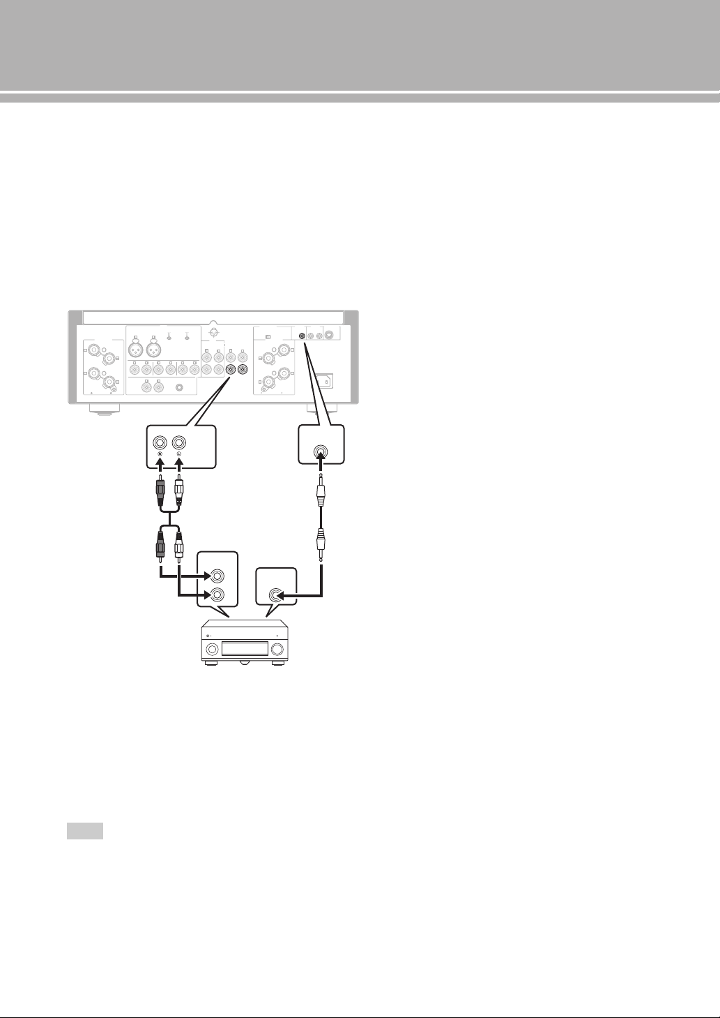
■ Connecting a component supporting
the trigger function such as a Yamaha
AV receiver
The operations of this unit can be controlled in
synchronization with the operations of the connected
component, such as a Yamaha AV receiver (power ON/
STANDBY or MAIN DIRECT input selection).
Connect the PRE OUT jacks and the TRIGGER OUT jack
of the Yamaha AV receiver to this unit as illustrated
below:
When the power of the connected component is turned on,
this unit turns on and the input is set to MAIN DIRECT
automatically.
When MAIN DIRECT is selected as the input source, this
unit enters STANDBY mode if the power of the connected
component is turned off.
To enable synchronization, turn off this unit before connecting
the component to the MAIN IN jacks. The synchronization
cannot be activated when the STANDBY/ON, OFF switch of the
unit has been set to OFF.
Note
GND
PHONO
LINE 1
CD
BAL
(-6dB)
ATT. IN V.
BYPASS NORMAL
PHASE
ATTENUATOR
INPUT
SPEAKERS R CH
A
B
+
+
A OR B:4 MIN. /SPEAKER
A+B:8 MIN. /SPEAKER
R L
R R
R
L
TUNER
LINE2
REC
PB
MAIN IN
L
L
L
R
R R
L
L
PRE OUT
AUTO POWER STANDBY
ON
OFF
SPEAKERS L CH
A
B
+
+
TRIGGER
REMOTE
SYSTEM CONNECTOR
IN IN OUT
AC IN
A OR B:4 MIN. /SPEAKER R
A+B:8 MIN. /SPEAKE
NORMAL (EIA)
+ HOT
- COLD
GND
12
3
TRIGGER
OUT
PRE OUT
TRIGGER
IN
MAIN IN
Rear panel of A-S2100
Yamaha AV receiver, etc.
with PRE OUT and
TRIGGER OUT jacks
RCA stereo
cable
Monaural mini-plug
cable
Specifications
In this section, you will find technical specifications for A-S2100.

24 En
Specifications
POWER SECTION
• Rated Output Power
[U.S.A, Canada, Taiwan, China, Korea, Australia, U.K. and
Europe models]
(8 , 20 Hz to 20 kHz, 0.07% THD) ...................... 90 W + 90 W
(4 , 20 Hz to 20 kHz, 0.07% THD) .................. 150 W + 150 W
[Asia model]
(8 , 20 Hz to 20 kHz, 0.07% THD) ...................... 90 W + 90 W
(6 , 20 Hz to 20 kHz, 0.07% THD) ...................110 W + 110 W
• Dynamic Power (IHF)
W W
W W
W W
W W
• Dynamic Headroom
(8 .................................................................................. 0.67 dB
• Maximum Output Power
[U.K. and Europe models only]
(1 kHz, 0.7% THD, 4 )...................................... 160 W + 160 W
• Maximum Effective Output Power (JEITA)
[Taiwan, China, Korea, Asia and U.K. models only]
(1 kHz, 10% THD, 8 )........................................ 120 W + 120 W
(1 kHz, 10% THD, 4 )........................................ 190 W + 190 W
• IEC Output Power [U.K. and Europe models only]
(1 kHz, 0.02% THD, 8 )......................................... 95 W + 95 W
• Power Bandwidth
(MAIN L/R, 0.1% THD, 45 W, 8 ) .................. 10 Hz to 50 kHz
• Damping Factor
(1 kHz, 8 ..............................................................250 or higher
• Maximum Input Signal Voltage
PHONO MM (1 kHz, 0.5% THD) ............................... 50 mVrms
PHONO MC (1 kHz, 0.5% THD) ............................... 2.2 mVrms
CD, etc. (1 kHz, 0.5% THD) ......................................... 2.80 Vrms
BAL (1 kHz, 0.5% THD)
(BYPASS) .................................................................. 2.80 Vrms
(ATT. -6 dB) .................................................................5.60 Vrms
• Rated Output Voltage/Output Impedance
REC OUT ..................................................... 200 mVrms/1.5 k
PRE OUT ......................................................... 1.0 Vrms/1.5 k
• Frequency Response
CD, etc. (5 Hz to 100 kHz) ............................................ +0/3dB
CD, etc. (20 Hz to 20 kHz) ......................................... +0/0.3 dB
• RIAA Equalization Deviation
PHONO MM .................................................................... ±0.5 dB
PHONO MC ..................................................................... ±0.5 dB
• Total Harmonic Distortion Plus Noise
PHONO MM to REC OUT
(20 Hz to 20 kHz, 1.2 Vrms ............................................ 0.005%
PHONO MC to REC OUT
(20 Hz to 20 kHz, 1.2 Vrms .............................................. 0.02%
BAL to SPEAKERS OUT
(20 Hz to 20 kHz, 50 W/8 )........................................... 0.025%
CD, etc. to SPEAKERS OUT
(20 Hz to 20 kHz, 50 W/8 )........................................... 0.025%
• Signal to Noise Ratio (IHF-A Network)
PHONO MM (5 mVrms, Input shorted) .............................. 93 dB
PHONO MC (500 µVrms, Input shorted) ........................... 85 dB
CD, etc. (200 mVrms, Input shorted) ................................. 103 dB
• Residual Noise (IHF-A Network) .................................... 33 µVrms
CONTROL SECTION
• Input Sensitivity/Input Impedance
CD, etc. ............................................................ 200 mVrms/47 k
PHONO MM .................................................... 2.5 mVrms/47 k
PHONO MC ....................................................... 100 µVrms/50
MAIN IN .............................................................. 1.0 Vrms/47 k
BAL ................................................................ 200 mVrms/100 k
• Headphone Jack Rated Output Power
CD, etc. (1 kHz, 32 , 0.2% THD) ................... 50 mW + 50 mW
• Channel Separation
CD, etc. (Input, 5.1 k Terminated, 1 kHz/10 kHz)
...................................................................... 74/54 dB or higher
PHONO MM (Input shorted, 1 kHz/10 kHz, Vol.:30 dB)
....................................................................... 90/77 dB or higher
PHONO MC (Input shorted, 1 kHz/10 kHz, Vol.:30 dB)
....................................................................... 66/77 dB or higher
• Tone Control Characteristics
BASS
Boost/Cut (50 Hz) ............................................................. ±9 dB
Turnover Frequency ........................................................ 350 Hz
TREBLE
Boost/Cut (20 kHz) ........................................................... ±9 dB
Turnover Frequency........................................................ 3.5 kHz
GENERAL
• Power Supply
[U.S.A and Canada models] ............................... AC 120 V, 60 Hz
[Taiwan model]................................................... AC 110 V, 60 Hz
[China model]..................................................... AC 220 V, 50 Hz
[Korea model]..................................................... AC 220 V, 60 Hz
[Australia model]................................................ AC 240 V, 50 Hz
[U.K. and Europe models].................................. AC 230 V, 50 Hz
[Asia model] ......................................... AC 220 - 240 V, 50/60 Hz
• Power Consumption
[Asia model] .........................................................................250 W
[Other models]..................................................................... 350 W
• Standby Power Consumption ...................................................0.3 W
• Dimensions (W × H × D) ................................ 435 × 157 × 463 mm
(17-1/8” × 6-1/8” × 18-1/4”)
• Weight................................................................... 23.4 kg (51.6 lbs)
* Specifications are subject to change without notice.
25 En
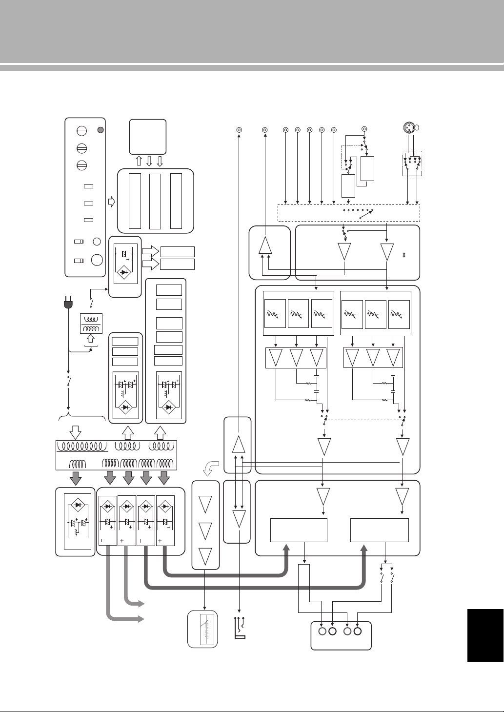
■ Block diagram
CD
TUNER
LINE1
LINE2
LINE2 OUT
PHONO
INPUT SELECTOR
ATT.UINT1
PRE OUT
MAIN IN
MM//MC
FLOATING BALANCE
SPEAKER DRIVER
MOSFET
L CH
FLOATING POWER SUPPLY
FLOATING BALANCE
POWER AMPLIFIER
VOLUME
BALANCE GAIN SEL
MAIN
TRANSFORMER
INDEPENDENT REGULATED POWER SUPPLY (for AUDIO)
FOR
MC AMP
FOR
MM EQ AMP
FOR
After Vol Amp
FOR
Input Amp
FOR
VOLUME1 (Lch)
SUB TRANSFORMER
(REC)
VOLUMEINPUT
BALANCE BASS
CPU
CONTROL
PROTECTION
SPEAKER OUT
FRONT PANEL
SP A Lch
SP B Lch
BAL
ATT.UINT2
ATT.UINT3
ATT.UINT1
ATT.UINT2
ATT.UINT3
LOW IMPEDANCE DRIVE
HEADPHONE AMP.
HEAD PHONE
TRIGGER IN
BUFFER AMP
FLOATING BALANCE
SPEAKER DRIVER
MOSFET
TONE CONTROL
REC OUT BUFFER
POWER RELAY
L CH
L CH
R CH
R CH
RELAY
MOTOR VOL
FOR
VOLUME2 (Rch)
METER
IR IN
IR OUT
Standby power
CPU/LOGIC, etc.
METER
PHONES
TRIM
SPEAKERS
OFF/A/B/A+B
METER
OFF/PEAK/VU
PHONO
MM/MC
AUDIO MUTE
REAR PANEL
METER UNIT
HOT
(
+
)
COLD (-)
Phase change
(normal / inv.)
UNBALANCE
BALANCE
CONVERTER
BUFFER AMP
MC
HEAD AMP
MM EQ
AMP
PRE OUT BUFFER
POWER AMP PRE STAGE
HOT
(
+
)
COLD (-)
FLAT (DEFEAT)
FLAT (DEFEAT)
TONE CONTROL
METER CIRCUIT
To POWER AMP
R CH
Lo
g
am
p
lifie
r
Peak / VU DRIVER
A
B
+
–
+
–
TREBLE
IR
REMOTE
English
26 En
Specifications
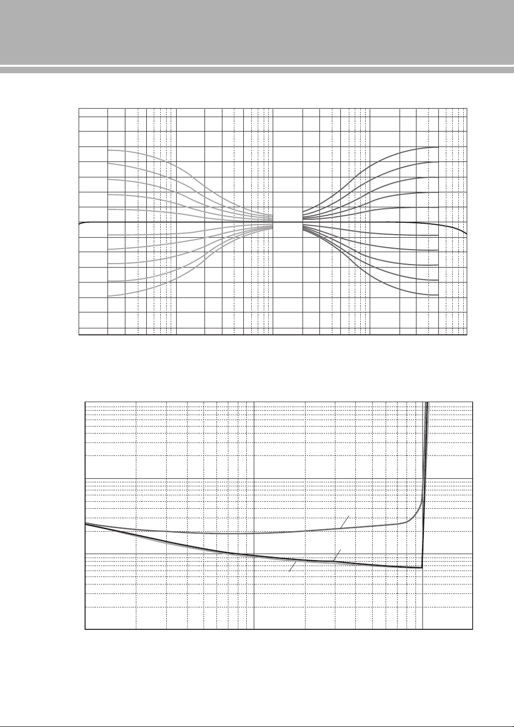
■ Tone control characteristics
■ Total harmonic distortion
10 20 30 50 100 200 300 500 1k
Frequency (Hz)
Response (dB)
2k 3k 5k 10k 20k 30k 50k 100
k
–14
–12
–10
–8
–6
–4
–2
0
2
4
6
8
10
12
14
0.001
0.002
0.003
0.005
0.01
0.02
0.05
0.03
0.1
0.2
0.3
0.5
1
1056 8234 10050 60 8020 30 401
Measured (W)
THD + N Ratio (%)
20Hz
1kHz
20kHz
27 En
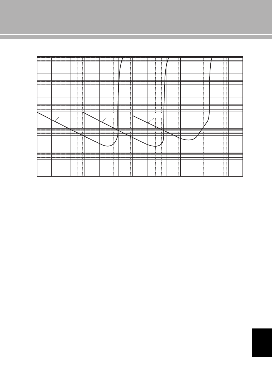
■ Total harmonic distortion (PHONO)
100µ 200µ 500µ 1m 2m 5m 10m 20m
Generator Level (Vrms)
50m 100m 200m 500m 1 2
20Hz 1kHz 20kHz
10
5
2
3
1
0.5
0.2
0.3
0.02
0.03
0.002
0.003
0.0002
0.0003
0.1
0.01
0.001
0.0001
0.05
0.005
0.0005
THD + N Ratio (%)
English
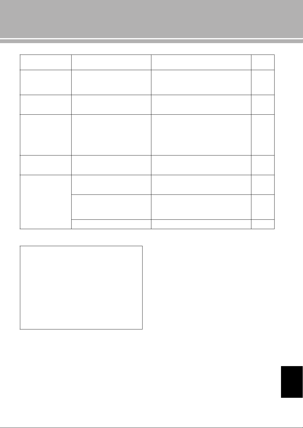
28 En
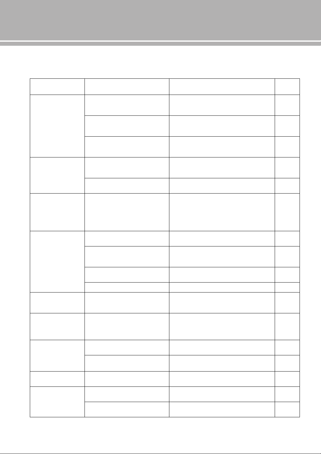
Troubleshooting
Refer to the chart below if this unit does not function properly. If the problem you are experiencing is not listed below or
if the instructions below do not help, turn off this unit, disconnect the power cable, and contact the nearest authorized
Yamaha dealer or service center.
Problem Cause Remedy
See
page
This unit fails to turn
on.
The power cable is not connected to the
AC IN inlet on the rear panel or not
plugged in the AC wall outlet.
Connect the power cable firmly.
19
The protection circuitry has been activated
because of a short circuit, etc.
Check that the speaker wires are not touching each
other or shorting out against the rear panel of this
unit, and then turn the power of this unit back on.
18
This unit has been exposed to a strong
external electric shock (such as lightning
or strong static electricity).
Turn off this unit, disconnect the power cable, plug it
back in after 30 seconds, and then use it normally.
—
The STANDBY/ON
indicator on the front
panel flashes.
The protection circuitry has been activated
because of a short circuit, etc.
Check that the speaker wires are not touching each
other or shorting out against the rear panel of this
unit, and then turn the power of this unit back on.
18
There is a problem with the internal
circuitries of this unit.
Disconnect the power cable and contact the nearest
authorized Yamaha dealer or service center.
—
The INPUT indicator
on the front panel
flashes and the
volume is turned
down when you turn
on this unit.
The protection circuitry has been activated
because of a short circuit, etc.
Check that the speaker wires are not touching each
other or shorting out against the rear panel of this
unit, and then turn the power of this unit back on.
18
No sound. Incorrect input or output cable
connections.
Connect the cables properly. If the problem persists,
the cables may be defective.
16
No appropriate input source has been
selected.
Select an appropriate input source with the INPUT
selector on the front panel (or one of the input
selector keys on the remote control).
8, 12
The SPEAKERS selector is set to OFF. Switch the SPEAKERS selector to the appropriate
position.
7
Speaker connections are not secure. Secure the connections.
18
The sound suddenly
goes off.
The protection circuitry has been activated
because of a short circuit, etc.
Check that the speaker wires are not touching each
other or shorting out against the rear panel of this
unit, and then turn the power of this unit back on.
18
The volume level
cannot be adjusted.
MAIN DIRECT is selected as the input
source.
Adjust the volume on the connected component.
Or connect external component to input jacks other
than MAIN IN and select the corresponding input
source.
8, 9
Only the speaker on
one side can be
heard.
Incorrect cable connections. Connect the cables properly. If the problem persists,
the cables may be defective.
16
Incorrect setting for the BALANCE
control.
Set the BALANCE control to the appropriate
position.
7
There is a lack of bass
and no ambience.
The + and – wires are connected in
reverse at the amplifier or the speakers.
Connect the speaker wires to the correct + and –
phase.
16
A “humming” sound
is heard.
Incorrect cable connections. Connect the audio cable plugs firmly. If the problem
persists, the cables may be defective.
16
No connection from the turntable to the
GND terminal.
Connect the turntable to the GND terminal of this
unit.
16
29 En
Problem Cause Remedy
See
page
The sound from the
component
connected to the BAL
jack is degraded.
The sound level is higher than the
maximum input level for the XLR
balanced input jacks.
If the output level of the connected component is
double, set the ATTENUATOR selector located
above the input jacks to ATT. (-6 dB).
20
Bass is not spatial
when BAL (balanced
input) is selected.
The polarity is incorrect. Select the correct polarity with the PHASE selector.
20
The sound is
degraded when
listening with the
headphones
connected to the CD
player connected to
this unit.
The power of this unit is turned off. Turn on the power of this unit.
—
The volume level is
low while playing a
record.
Incorrect setting for the PHONO switch
on the front panel.
Switch the PHONO switch to the MM or MC position
according to the type of magnetic cartridge of the
turntable.
9
The remote control
does not work or
function properly.
Wrong distance or angle. The remote control functions within a maximum
range of 6 m (20 ft) and no more than 30 degrees off-
axis from the front panel.
14
Direct sunlight or lighting (from an
inverter type of fluorescent lamp, etc.) is
striking the remote control sensor of this
unit.
Reposition this unit.
8
The batteries are weak. Replace all batteries.
14
Taking care of this unit
Polish finish on the side panels
Use of Yamaha Unicon cloth (sold separately) is
recommended. For heavy dirt, use Yamaha Piano
Unicon (sold separately). For puschasing, contact your
nearest authorized Yamaha dealer or service center.
Other finish
When you wipe this unit, do not use chemical solvents
(alcohol, thinner, etc.), which might damage the finish.
Use a clean, dry cloth. For heavy dirt, dampen a soft
cloth in detergent diluted with water, wring it out, and
clean this unit with the cloth.
English
2 Fr
Faire vivre la tradition du son
Un piano vient au monde grâce à la synergie parfaite entre une expertise technique avancée
et des talents artistiques. Un tel piano peut créer un son qui reflète vraiment les sentiments
de l’interprète.
L’étape finale de la production d’un piano est appelée « harmonisation ». C’est à ce
moment-là que l’on donne son âme à l’instrument.
Un expert hautement qualifié concentre son esprit et sa sensibilité sur le son de chaque
touche, en ajustant avec finesse la sensation dynamique des marteaux et en harmonisant
parfaitement la tonalité et la vibration de l’ensemble des 88 touches. C’est une réalisation
vraiment exceptionnelle.
Seule une oreille sensible et fine peut déterminer une telle qualité sonore. Nous appliquons
ce même concept à la fabrication de nos produits audio. Le technicien effectue des tests
d’écoute approfondis et chaque composant est étudié avant d’obtenir finalement le son
idéal.
La tradition de la qualité audio de Yamaha remonte à plus de 125 ans et est toujours
présente dans l’ensemble des produits Yamaha actuels.
3 Fr
NP-S2000
Soavo-1
NS-10M
A-S3000
CD-S3000
NS-20
CA-1000
NS-690
B-1
PX-2
C-2
NS-1000M
A-1
B-6
B-2x
MX-10000
CX-10000
L’excellence dans l’accomplissement audio
Amplificateur intégré CA-1000
Faisant partie des appareils de Classe A, le CA-1000 est
devenu la norme pour les amplificateurs intégrés.
Enceinte Natural Sound NS-690
Enceinte de contrôle NS-1000M
Une enceinte véritablement légendaire, toujours vénérée
par les passionnés de Hi-Fi.
Amplificateur de puissance B-1
Un ampli innovant utilisant des transistors FET à tous
les étages.
Amplificateur de commande C-2
A reçu le premier prix au Salon International de la
Musique et de la Hi-Fi de Milan.
Enceinte de contrôle pour studio NS-10M
Devenue l’une des enceintes de studio les plus populaires
au monde.
Amplificateur intégré A-1
Tourne-disque PX-2
Le premier tourne-disque à bras droit de Yamaha.
Amplificateur de puissance B-6
Amplificateur de puissance pyramidal.
Tourne-disque GT-2000/L
Premier lecteur de CD (CD-1) commercialisé
en 1983
Amplificateur de puissance B-2x
Amplificateur de puissance MX-10000 et
Amplificateur de commande CX-10000
Ont redéfini les fonctionnalités des composants séparés.
Amplificateur intégré AX-1
Lecteur de CD GT-CD1
Amplificateur de puissance MX-1 et
préamplificateur CX-1
Systèmes d’enceintes Natural Sound Soavo-1
et Soavo-2
Amplificateur intégré A-S2000 et Lecteur de
CD CD-S2000
Lecteur réseau NP-S2000
Amplificateur intégré A-S3000 et Lecteur de
CD CD-S3000
Premier Système Hi-Fi introduit en 1920
Nous avons introduit de nombreux
composants Hi-Fi (tourne-disques, tuners
FM/AM, amplificateurs intégrés, préamplis,
amplificateurs de puissance et enceintes) en
1955 – 1965.
Commercialisation de la série d’enceintes
Natural Sound en 1967
Enceinte de contrôle NS-20

4 Fr
◆ La conception des circuits entièrement à symétrie flottante permet
d’atteindre tout le potentiel de l’amplification analogique
Un tout nouvel amplificateur de puissance à symétrie flottante qui atteint une parfaite symétrie et permet une
transmission totalement symétrique (amplification) depuis la prise d’entrée jusque devant la prise d’enceinte.
◆ Transmission du signal symétrique à tous les étages
Cet amplificateur intégré offre une transmission symétrique sur tous les étages, combinant à la fois une grande puissance
de sortie avec une bonne texture sonore et une performance R/N exceptionnelle.
◆ Commandes de volume et de tonalité parallèles
◆ Sources d’alimentation de grande capacité avec quatre circuits séparés
◆ Conception symétrique gauche-droite avec construction rigide et stable
◆ Amplificateur phono discret
◆ Amplificateur de casque de haute qualité avec circuit d’attaque à basse
impédance
■ Accessoires fournis
Veuillez vous assurer que tous les articles suivants vous ont bien été fournis.
• Boîtier de télécommande
• Piles (AAA, R03, UM-4) (×2)
• Câble d’alimentation
• BROCHURE SUR LA SÉCURITÉ
■ À propos de ce manuel
• Le symbole y appelle votre attention sur un conseil d’utilisation.
• Les photographies et illustrations de ce mode d'emploi sont uniquement utilisées dans un but explicatif. Il se pourrait qu'elles diffèrent
du produit.
• Avant d’utiliser cet appareil, veuillez lire la « BROCHURE SUR LA SÉCURITÉ ».
Table des matières
Commandes et fonctions....................................................................................................................................... 6
Raccordements .................................................................................................................................................... 16
Caractéristiques techniques ............................................................................................................................... 24
Guide de dépannage............................................................................................................................................ 28

5 Fr
Commandes et
fonctions
Ce chapitre décrit les commandes et fonctions de l’A-S2100.
6 Fr
Commandes et fonctions
■ Panneau avant (pages 6 à 9)
1 Commutateur STANDBY/ON, OFF
Met l’appareil sous tension ou hors tension.
STANDBY/ON (position supérieure) : Dans cette
position, vous pouvez sélectionner STANDBY ou
ON à l’aide de la touche
p AMP du boîtier de télécommande.
OFF (position inférieure) : L’appareil est hors
service.
• Lorsque vous mettez l’appareil sous tension, celui-ci met
quelques secondes à reproduire le son.
• Si vous débranchez le câble d’alimentation secteur de la
prise secteur et le rebranchez lorsque cet appareil est en
mode STANDBY, l’appareil est mis sous tension. Si
l’appareil n’est pas utilisé pendant une période prolongée,
réglez le commutateur STANDBY/ON, OFF sur OFF.
2 Témoin STANDBY/ON
Fortement allumé : Indique que l'appareil est sous
tension. Dans cet état, vous pouvez mettre
l’appareil en mode STANDBY en appuyant sur la
touche p AMP du boîtier de télécommande.
Faiblement allumé : Indique que l'appareil est en
mode STANDBY. Dans cet état, vous pouvez
mettre l’appareil sous tension en appuyant sur la
touche p AMP du boîtier de télécommande.
Éteint : Indique que l'appareil est hors tension. Dans
cet état, vous pouvez mettre l'appareil sous tension
uniquement en appuyant sur le commutateur
STANDBY/ON, OFF du panneau avant.
3 Prise PHONES
Fournit les signaux audio destinés à l’écoute au
casque.
• Lorsqu’un casque est branché :
– Les deux paires d’enceintes raccordées aux bornes
SPEAKERS L/R CH sont désactivées.
– Aucun signal n’est transmis aux prises PRE OUT.
– Vous ne pouvez pas sélectionner MAIN DIRECT
comme source d’entrée.
• Si le casque est branché sur la prise PHONES lorsque
MAIN DIRECT est sélectionné comme source d’entrée,
aucun son n’est transmis à la prise PHONES.
METER
PEAK
OFF
VU
INPUT
BAL
CD
TUNER
LINE 1
PHONO
LINE 2
MAIN DIRECT
BASS
–+
TREBLE
–+
BALANCE
LR
STANDBY/ON PHONES TRIM
0
-6 +6
+12
SPEAKERS
A
OFF B
A+B
BI-WIRING
dB
OFF
1 2 3 4
5 6 7 8 9 :
Remarques
Remarques
7 Fr
4 Sélecteur TRIM
Ajuste le niveau sonore lorsque le casque est branché
pour éviter les changements subits de volume.
Choix : –6 dB, 0 dB, +6 dB, +12 dB
5 Sélecteur SPEAKERS
Active ou désactive la paire d’enceintes raccordées
aux bornes SPEAKERS L/R CH A et/ou B situées sur
le panneau arrière.
OFF : Les deux paires d'enceintes sont désactivées.
A/B : La paire d'enceintes connectée aux prises A ou
B est active.
A+B BI-WIRING : Les deux paires d'enceintes sont
activées.
Si vous utilisez deux paires (A et B), l’impédance de chaque
enceinte doit être de 8 Ω ou plus.
6 Sélecteur METER
Commute l’affichage du compteur sur OFF, PEAK ou
VU.
OFF: Éteint le compteur et l’éclairage.
PEAK : Bascule le compteur sur un PEAK-mètre. Le
PEAK-mètre indique le niveau de sortie audio le
plus élevé du moment.
VU : Bascule le compteur sur un VU-mètre (VU
signifiant unité de volume). Le VU-mètre indique
une valeur de sortie audio effective semblable aux
sens humains.
7 Affichages du compteur (LEFT/RIGHT)
Indique le niveau de sortie audio des voies gauche
(LEFT) et droite (RIGHT) en mode de compteur VU
ou PEAK.
Il est possible de sélectionner le compteur VU ou
PEAK avec le sélecteur METER.
8 Commande BASS
Augmente ou diminue la réponse dans les basses
fréquences. La position 0 correspond à une réponse
plate.
Plage de réglage : –10 dB à +10 dB
9 Commande TREBLE
Augmente ou diminue la réponse dans les hautes
fréquences. La position 0 correspond à une réponse
plate.
Plage de réglage : –10 dB à +10 dB
0 Commande BALANCE
Équilibre le son fourni par les enceintes gauche et
droite pour compenser le déséquilibre dû à la
disposition des enceintes ou à la configuration de la
pièce.
• Lorsque les commandes BASS et TREBLE sont toutes deux sur
la position 0, le signal audio ne passe pas par le circuit de
commandes de tonalité.
• Les commandes BASS, TREBLE et BALANCE n’affectent pas
l’entrée des signaux dans les prises MAIN IN et la sortie des
signaux des prises LINE 2 REC.
Avertissement
AUDIO MUTE
VOLUME
PHONO
MM
MC
Remarques
Français
8 Fr
Commandes et fonctions
■ Panneau avant (pages 6 à 9)
A Capteur de télécommande
Il reçoit les signaux émis par le boîtier de
télécommande.
B Sélecteur/Témoin INPUT
Sélectionne la source d’entrée à lire. Le témoin de la
source d’entrée sélectionnée avec le sélecteur INPUT
s’allume.
Les signaux audio de la source d’entrée sélectionnée
sont aussi transmis aux prises LINE 2 REC.
MAIN DIRECT : Sélectionne le composant branché
aux prises MAIN IN.
Lorsque MAIN DIRECT est sélectionné comme
source d’entrée, les signaux audio ne sont pas
transmis aux prises PRE OUT, LINE 2 REC et
PHONES.
LINE 1/LINE 2 : Sélectionne le composant branché
aux prises LINE 1 ou LINE 2.
BAL : Sélectionne le composant branché aux prises
BAL (prises XLR symétriques).
CD : Sélectionne le lecteur de CD branché aux prises
CD (prises RCA asymétriques).
TUNER : Sélectionne le syntoniseur branché aux
prises TUNER.
PHONO : Sélectionne le tourne-disque branché aux
prises PHONO.
Lorsque LINE 2 est sélectionné, les signaux audio ne sont
pas transmis aux prises LINE 2 REC.
METER
PEAK
OFF
VU
INPUT
BAL
CD
TUNER
LINE 1
PHONO
LINE 2
MAIN DIRECT
BASS
–+
TREBLE
–+
BALANCE
LR
STANDBY/ON PHONES TRIM
0
-6 +6
+12
SPEAKERS
A
OFF B
A+B
BI-WIRING
dB
OFF
A B
Remarque

9 Fr
C Commutateur PHONO
Sélectionne le type de cartouche magnétique du
tourne-disque raccordé aux prises PHONO situées sur
le panneau arrière.
MM : Choisissez ce réglage si le tourne-disque
raccordé dispose d'une cartouche à aimant mobile
(MM).
MC : Choisissez ce réglage si le tourne-disque
raccordé dispose d'une cartouche à bobine mobile
(MC).
y
Avant de remplacer la cartouche, veillez à mettre cet appareil
hors tension.
D Commutateur AUDIO MUTE
Appuyez vers le bas pour réduire le niveau sonore
d’environ 20 dB. Appuyez une nouvelle fois sur cette
touche pour rétablir le niveau sonore initial.
y
Vous pouvez aussi tourner la commande VOLUME du
panneau avant ou appuyer sur la touche VOLUME + ou – du
boîtier de télécommande pour rétablir le son.
E Témoin AUDIO MUTE
S’allume lorsque le silencieux est activé avec le
commutateur AUDIO MUTE.
F Commande VOLUME
Contrôle le niveau sonore. Elle est sans effet vis-à-vis
du niveau de sortie des prises LINE 2 REC.
La commande VOLUME n’agit pas lorsque vous
sélectionnez MAIN DIRECT comme source d’entrée. Réglez
le niveau sonore avec la commande de volume de
l’amplificateur externe raccordé aux prises MAIN IN.
AUDIO MUTE
VOLUME
PHONO
MM
MC
C
D E
F
Remarque
Français
10 Fr
Commandes et fonctions
■ Panneau arrière
1 Prises d’entrée BAL (symétriques)
Un jeu de prises d’entrée symétriques est fourni.
Réglez le sélecteur ATTENUATOR et le sélecteur
PHASE de façon appropriée en fonction du lecteur
branché. Pour plus de détails sur ces sélecteurs, voir
page 20.
2 Prises PRE OUT
y
• Les prises PRE OUT transmettent le signal de la même
voie que les bornes SPEAKERS L/R CH.
• Lorsque vous raccordez un câble stéréo aux prises PRE
OUT pour que les enceintes soient entraînées par un
amplificateur externe, vous n’avez pas besoin d’utiliser les
bornes SPEAKERS L/R CH.
• Les signaux transmis aux prises PRE OUT sont modifiés en
fonction des réglages des commandes BASS et TREBLE.
3 Bornes SPEAKERS L/R CH
4 Prises d’entrée TUNER
5 Prises d’entrée PHONO
6 Prises d’entrée CD
7 Borne GND (masse)
8 Prises d’entrée LINE 1
9 Prises LINE 2
Les prises d’entrée PB (lecture) et les prises de sortie
REC (enregistrement) sont fournies.
0 Prises MAIN IN
Utilisez ces prises pour raccorder un composant
externe équipé d’une commande de volume.
y
Lorsque vous sélectionnez MAIN DIRECT comme source
d’entrée, le niveau sonore est fixe.
Réglez le niveau sonore avec la commande de volume de
l’amplificateur externe branché aux prises MAIN IN lorsque
vous sélectionnez MAIN DIRECT comme source d’entrée.
Pour le branchement aux prises MAIN IN, voir pages 16 et 17.
GND
PHONO
LINE 1
CD
BAL
(-6dB)
ATT. INV.
BYPASS NORMAL
PHASE
ATTENUATOR
INPUT
SPEAKERS R CH
A
B
+
+
A OR B:4 MIN. /SPEAKER
A+B:8 MIN. /SPEAKER
R L
R R
R
L
TUNER
LINE2
REC
PB
MAIN IN
L
L
L
R
R R
L
L
PRE OUT
NORMAL (EIA)
+ HOT
- COLD
GND
12
3
1 2
3 4
5 6 7 8 9 0
Voir page 16 en ce qui concerne les raccordements.
11 Fr
A Commutateur AUTO POWER STANDBY
ON : L’appareil entre automatiquement en mode
STANDBY s’il n’est pas utilisé pendant 8 heures.
OFF : L’appareil n’entre pas automatiquement en
mode STANDBY.
B Prise TRIGGER IN
Utilisez cette prise afin de brancher un composant
externe pour la fonction de déclenchement.
Pour plus de détails sur le raccordement, voir page 22.
C Prises REMOTE IN/OUT
Utilisez ces prises afin de raccorder un composant
externe pour le boîtier de télécommande.
Pour plus de détails sur le raccordement, voir page 21.
D SYSTEM CONNECTOR
Utilisez ce connecteur pour brancher un dispositif de
test de produits pour l’entretien.
E Prise AC IN
Utilisez cette prise pour brancher le câble
d’alimentation secteur fourni.
Pour plus de détails sur le raccordement, voir page 19.
F Pied
Les pieds de cet appareil sont pourvus de crampons.
Utilisez ces crampons pour réduire l’effet des
vibrations sur l’appareil. Lorsque vous utilisez les
crampons, retirez la bande de transport, puis ôtez le
pied magnétique en tirant sur celui-ci.
• Veillez à ce que de jeunes enfants ne risquent pas d'avaler
accidentellement le pied magnétique.
• Les crampons des pieds peuvent rayer l’étagère ou la
surface où vous installez cet appareil lorsque vous les
utilisez. Utilisez les pieds magnétiques ou des supports
appropriés pour placer cet appareil sur des meubles de
valeur, etc.
y
Si l’appareil n’est pas stable, vous pouvez ajuster la hauteur
d’un pied en le tournant.
AUTO POWER STANDBY
ON
OFF
SPEAKERS L CH
A
B
+
+
TRIGGER
REMOTE
SYSTEM CONNECTOR
IN IN OUT
AC IN
A OR B:4 MIN. /SPEAKER
A+B:8 MIN. /SPEAKE
R
A B C D
E
3 F
Avertissement
Crampon
Bande de
transport
Pied
magnétique
Français
12 Fr
Commandes et fonctions
■ Boîtier de télécommande
1 Émetteur de signal infrarouge
Émet des signaux de commande infrarouges.
2 Touche p AMP
Met cet appareil sous tension ou le bascule en mode
STANDBY.
Pour plus de détails sur le mode STANDBY, voir
« Panneau avant » (page 6).
3 Touches de sélection d’entrée
Sélectionne la source d’entrée à lire.
Les signaux audio de la source d’entrée sélectionnée
sont transmis aux prises LINE 2 REC.
y
Lorsque LINE 2 est sélectionné comme source d’entrée, les
signaux audio ne sont pas transmis aux prises LINE 2 REC.
BAL : Sélectionne le composant branché aux prises
BAL (prises XLR symétriques).
LINE : Sélectionne le composant branché aux
prises LINE 1 ou LINE 2.
PHONO : Sélectionne le tourne-disque branché aux
prises PHONO.
MAIN DIRECT : Sélectionne le composant branché
aux prises MAIN IN. Lorsque MAIN DIRECT est
sélectionné comme source d’entrée, les signaux
audio ne sont pas transmis aux prises PRE OUT,
LINE 2 REC et PHONES.
CD : Sélectionne le lecteur de CD branché aux prises
CD (prises RCA asymétriques).
TUNER : Sélectionne le syntoniseur branché aux
prises TUNER.
4 Touches de commande du syntoniseur
Yamaha
Commandent des fonctions du syntoniseur Yamaha.
Reportez-vous au mode d’emploi du syntoniseur pour
le détail.
Certains syntoniseurs Yamaha ne peuvent pas être
commandés par ce boîtier de télécommande.
4
2
1
3
8
9
5
7
6
AMP CD
OPEN/CLOSE
BAL
LINE LINE
PRESET
12
PHONO
MAIN DIRECT
CD TUNER
BAND
MUTE
SOURCE LAYER
VOLUME
Remarque

13 Fr
5 Touche p CD
Met le lecteur de CD Yamaha sous tension ou le
bascule en mode STANDBY.
6 Touche OPEN/CLOSE
Ouvre/Ferme le tiroir du lecteur de CD Yamaha.
Reportez-vous au mode d’emploi du lecteur de CD
pour le détail.
Certains lecteurs de CD Yamaha ne prennent pas en charge la
touche p
CD et/ou la touche OPEN/CLOSE de ce
boîtier de télécommande.
7 Touches de commande du lecteur de CD
Yamaha
Commandent différentes fonctions du lecteur de CD
Yamaha. Reportez-vous au mode d’emploi du lecteur
de CD pour le détail.
(Lecture): Démarre la lecture.
(Pause): Met la lecture en pause. Appuyez sur
ou pour poursuivre la lecture.
(Stop): Arrête la lecture.
/ (Saut): Passe à la plage suivante ou
revient au début de la plage actuelle.
SOURCE: Sélectionne la source à lire sur le lecteur
de CD Yamaha. La source de lecture change à
chaque pression de cette touche.
LAYER: Sélectionne la couche de lecture SA-CD ou
CD d’un SA-CD hybride.
8 Touches VOLUME +/–
Commandent le niveau sonore.
Les touches VOLUME n’agissent pas lorsque vous
sélectionnez MAIN DIRECT comme source d’entrée. Réglez
le niveau de volume de l’amplificateur externe branché aux
prises MAIN IN.
9 Touche MUTE
Réduit le niveau sonore actuel d’environ
20 dB. Appuyez une nouvelle fois sur cette touche
pour rétablir le niveau sonore initial. Vous pouvez
également appuyer sur la touche VOLUME + ou –
pour annuler le silencieux.
Remarque
Remarque
Français
14 Fr
Commandes et fonctions
■ Mise en place des piles dans le boîtier
de télécommande
1 Retirez le couvercle du logement des piles.
2 Insérez les deux piles (AAA, R03, UM-4) en
suivant les repères de polarité (+ et –) à
l’intérieur du logement des piles.
3 Replacez le couvercle du logement des piles.
■ Portée du boîtier de télécommande
y
Le boîtier de télécommande émet un faisceau infrarouge
directionnel. Veillez à le pointer directement sur le capteur de
télécommande de l’appareil pour en assurer le
fonctionnement.
2
1
3
30 30
Environ 6 m

Raccordements
Dans cette section, vous allez raccorder l’A-S2100, les enceintes et les composants source.
16 Fr
Raccordements
• Faites en sorte que la partie dénudée d’un conducteur du câble
d’enceinte ne puisse pas venir en contact avec la partie dénudée
de l’autre conducteur, ni avec une pièce métallique de cet
appareil. Ce contact pourrait endommager l’appareil et/ou les
enceintes.
• Tous les raccordements doivent être corrects : L (gauche) à L, R
(droite) à R, « + » à « + » et « – » à « – ». Si le raccordement est
défectueux, aucun son n’est émis par l’enceinte, et si la polarité
du raccordement est incorrecte, les sons manquent de naturel et
de composantes graves. Reportez-vous aussi au mode d’emploi
de chaque appareil.
• Utilisez des câbles RCA asymétriques pour relier d’autres
appareils à l’exception des enceintes. Utilisez des câbles XLR
symétriques pour relier un lecteur de CD ou un lecteur réseau
pourvu de prises de sortie XLR symétriques aux prises BAL de
cet appareil.
• Raccordez votre tourne-disque à la borne GND pour réduire le
bruit parasitant le signal. Toutefois, avec certains tourne-
disques les parasites sont moins importants sans raccordement à
la borne GND.
Remarques
GND
PHONO
LINE1
CD
BAL
(-6dB)
ATT. INV.
BYPASS NORMAL
PHASE
ATTENUATOR
INPUT
SPEAKERS R CH
A
B
+
+
A OR B:4 MIN. /SPEAKER
A+B:8 MIN. /SPEAKER
R L
R R
R
L
TUNER
L
L
L
R
+
-
+
-
Lecteur de CD
avec prises RCA
Enceintes A
(voie R)
Enceintes B
(voie R)
Lecteur de CD ou lecteur
réseau pourvu de prises XLR
Syntoniseur
Tourne-disque
Masse
Lecteur de BD, etc.
17 Fr
• L’amplificateur de puissance de l’A-S2100 étant à symétrie flottante, il n’est pas
possible d’effectuer les types de raccordements suivants.
– Raccordement à la borne « – » de la voie gauche et à la borne « – » de la voie
droite de même qu’aux bornes « + » (Fig. 1).
– Raccordement en inversant la borne « – » de la voie gauche et la borne « – » de
la voie droite (raccordement croisé Fig. 2).
– Raccordement délibéré aux bornes « – » des voies gauche/droite et à une partie
métallique à l’arrière de cet appareil, ou simple toucher accidentel.
• Ne raccordez pas votre caisson de graves amplifié à la borne SPEAKERS L/R CH.
Raccordez-le aux prises PRE OUT de cet appareil.
• Ne raccordez pas un composant sans commande de volume, par exemple un
lecteur de CD, aux prises MAIN IN, car le niveau sonore de l’entrée des signaux
aux prises MAIN IN est fixe. Si un tel appareil est relié, un son peut éclater, et
l’appareil et/ou l’enceinte peut être endommagée.
Remarques
GND
LINE 1
-6dB)
TT. INV.
NORMAL
PHASE
TOR
LINE2
REC
PB
MAIN IN
L
R
R R
L
L
NORMAL (EIA)
+ HOT
- COLD
GND
12
3
PRE OUT
AUTO POWER STANDBY
ON
OFF
SPEAKERS L CH
A
B
+
+
TRIGGER
REMOTE
SYSTEM CONNECTOR
IN IN OUT
AC IN
A OR B:4 MIN. /SPEAKER
A+B:8 MIN. /SPEAKER
+–
+
-
Graveur de CD,
platine à cassette, etc.
Enceintes A
(voie L)
Enceintes B
(voie L)
Amplificateur externe ou
caisson de graves actif
Préamplificateur,
récepteur AV, etc.
Français
+
–
+
–
L
R
+
–
+
–
L
R
+
–
+
–
L
R
+
–
+
–
L
R
Fig. 1 Fig. 2

18 Fr
Raccordements
■ Raccordement des enceintes
1 Enlevez environ 10 mm de la gaine isolante à
l’extrémité de chaque câble d’enceinte et
torsadez les fils exposés du câble pour éviter
les courts-circuits.
2 Dévissez la borne, puis insérez la partie sans
gaine du fil dans l’orifice.
3 Revissez la borne.
Pour desserrer le bouton de la borne d’enceinte, ne le faites pas
tourner excessivement. Le bouton risque de se détacher et d’être
ingéré par un enfant.
• Le contact entre la borne de haut-parleur et une étagère
métallique peut provoquer un court-circuit et endommager cet
appareil. Pour installer l’appareil sur une étagère, maintenez
une distance suffisante pour éviter que les bornes d’enceinte ne
touchent l’étagère.
• Pour réduire le risque de choc électrique, ne touchez pas la
borne d’enceinte lorsque l’appareil est sous tension.
■ Raccordement d’une fiche banane
(Sauf modèle pour l’Europe)
Serrez d’abord le bouton et insérez la fiche
banane dans la prise correspondante.
■ Raccordement d’une cosse en Y
1 Dévissez la borne et insérez la cosse en Y
entre l’anneau et la base.
2 Revissez la borne.
Avertissement
Remarques
10 mm
Orifice pour câble d’enceinte :
6,0 mm de diamètre.
Fiche banane
Orifice pour fiche
banane : 3,95 mm de
diamètre
Cosse en Y
Faites glisser
Vis de borne pour fiche en Y :
5,8 mm de diamètre.
19 Fr
■ Connexion bifilaire
La connexion bifilaire a pour effet de séparer le grave du
médium et de l’aigu. Une enceinte compatible avec ce
type de connexion est pourvue de quatre bornes de
connexion. Ces deux jeux de bornes permettent de diviser
l’enceinte en deux sections indépendantes. Les circuits
d’attaque du médium et de l’aigu sont reliés à un jeu de
bornes et le circuit d’attaque du grave est relié à l’autre
jeu.
Exemple de connexion bifilaire (voie R)
Si vous utilisez des connexions bifilaires, l’impédance de chaque
enceinte doit être au moins égale à 8 Ω.
Détachez les barres de court-circuitage pour séparer les filtres
LPF (filtre passe bas) et HPF (filtre passe haut).
y
Pour utiliser les connexions bifilaires, mettez le sélecteur
SPEAKERS du panneau avant sur la position A+B BI-WIRING.
■ Raccordement du câble d’alimentation
Branchez le câble d’alimentation secteur sur la prise AC
IN lorsque tous les appareils ont été raccordés, puis
branchez-le sur la prise secteur.
Avertissement
Remarque
SPEAKERS R CH
A
B
+
+
A OR B:4 MIN. /SPEAKER
A+B:8 MIN. /SPEAKER
Panneau arrière de l’A-S2100
Enceinte
AC IN
vers une prise secteur
Câble d’alimentation
fourni
Panneau arrière de l’A-S2100
Français
20 Fr
Raccordements
■ Raccordement aux prises BAL
Raccordez votre lecteur de CD ou votre lecteur réseau aux
prises de sortie symétriques XLR.
Réglez le sélecteur ATTENUATOR et le sélecteur PHASE
situés au-dessus des prises BAL en fonction du composant
à raccorder.
Sélecteur ATTENUATOR :
Sélectionnez le niveau d’entrée admissible pour les prises
d’entrée symétriques XLR. Si le son du composant relié
est déformé, réglez le sélecteur ATTENUATOR sur ATT.
(-6 dB).
Sélecteur PHASE :
Sélectionnez l’attribution de la broche CHAUD des prises
d’entrée symétriques XLR (broche 2 CHAUD ou broche 3
CHAUD).
NORMAL (broche 2 CHAUD)
INV. (broche 3 CHAUD)
Reportez-vous au mode d’emploi fourni avec l’appareil
relié et vérifiez l’affectation de la broche CHAUD de ses
prises de sortie symétriques XLR.
y
Les lecteurs de CD Yamaha sont réglés sur NORMAL (broche 2
CHAUD).
Connecteurs XLR :
Pour le raccordement, faites correspondre les broches et
insérez le connecteur du câble XLR symétrique « mâle »
jusqu’à ce que vous entendiez un déclic. Pour le
débranchement, retirez le câble XLR symétrique « mâle »
tout en baissant le levier de la prise BAL.
Pour sélectionner le composant connecté aux prises BAL, réglez
la source d'entrée sur BAL.
1 : masse2 : chaud
3 : froid
1 : masse2 : froid
3 : chaud
Remarque
Connecteur XLR « femelle »
Connecteur XLR « mâle »
Levier
Prise BAL
21 Fr
■ Fonctionnement de cet appareil dans
une autre pièce
Si vous branchez un récepteur et un émetteur infrarouge
aux prises REMOTE IN/OUT de cet appareil, vous
pouvez utiliser l’appareil et/ou le composant externe à
l’aide du boîtier de télécommande fourni situé dans une
autre pièce.
■ Connexion à distance entre les
composants Yamaha
Lorsque vous avez un autre composant Yamaha prenant en
charge la connexion à distance, comme c’est le cas pour
cet appareil, un émetteur infrarouge est inutile. Vous
pouvez transmettre des signaux à distance en raccordant
un récepteur infrarouge et la prise REMOTE IN de l’autre
composant aux prises REMOTE IN/OUT de cet appareil,
avec des câbles à mini-fiches mono.
Il est possible de raccorder jusqu’à trois composants
Yamaha (cet appareil compris).
TRIGGER
REMOTE
SYSTEM CONNECTOR
IN IN OUT
Panneau arrière de l’A-S2100
Récepteur
infrarouge
Boîtier de télécommande
Émetteur
infrarouge
Composant externe
(lecteur de CD, etc.)
TRIGGER
REMOTE
SYSTEM CONNECTOR
IN IN OUT
REMOTE
IN OUT
Panneau arrière de l’A-S2100
Récepteur
infrarouge
Boîtier de télécommande
Composant Yamaha
(jusqu’à trois composants,
cet appareil compris)
Câble à mini-fiches
mono
Français
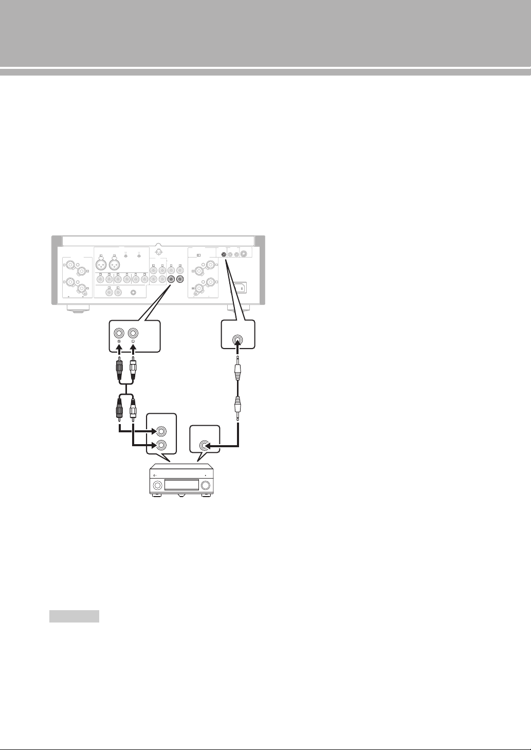
22 Fr
Raccordements
■ Raccordement d’un composant prenant
en charge la fonction de déclenchement
tel que le récepteur AV Yamaha
Les opérations de cet appareil peuvent être commandées
en synchronisation avec les opérations du composant
raccordé, comme un récepteur AV Yamaha (alimentation
sur ON/STANDBY ou sélection de l’entrée MAIN
DIRECT).
Branchez les prises PRE OUT et la prise TRIGGER OUT
du récepteur AV Yamaha à cet appareil comme illustré ci-
dessous :
Lorsque l’appareil raccordé est mis sous tension, il se met
en marche et l’entrée est automatiquement réglée sur
MAIN DIRECT.
Lorsque
MAIN DIRECT est sélectionné comme source
d’entrée, l’appareil entre en mode
STANDBY si
l’alimentation du composant raccordé est coupée.
Pour activer la synchronisation, mettez cet appareil hors tension
avant de brancher le composant aux prises MAIN IN. Il est
impossible d’activer la synchronisation lorsque le commutateur
STANDBY/ON, OFF de l’appareil a été réglé sur OFF.
Remarque
GND
PHONO
LINE 1
CD
BAL
(-6dB)
ATT. IN V.
BYPASS NORMAL
PHASE
ATTENUATOR
INPUT
SPEAKERS R CH
A
B
+
+
A OR B:4 MIN. /SPEAKER
A+B:8 MIN. /SPEAKER
R L
R R
R
L
TUNER
LINE2
REC
PB
MAIN IN
L
L
L
R
R R
L
L
PRE OUT
AUTO POWER STANDBY
ON
OFF
SPEAKERS L CH
A
B
+
+
TRIGGER
REMOTE
SYSTEM CONNECTOR
IN IN OUT
AC IN
A OR B:4 MIN. /SPEAKER R
A+B:8 MIN. /SPEAKE
NORMAL (EIA)
+ HOT
- COLD
GND
12
3
TRIGGER
OUT
PRE OUT
TRIGGER
IN
MAIN IN
Panneau arrière de l’A-S2100
Récepteur AV Yamaha
avec prises PRE OUT et
TRIGGER OUT
Câble stéréo
RCA
Câble à mini-fiches
mono
Caractéristiques
techniques
Dans cette section, vous trouverez les caractéristiques techniques de l’A-S2100.

24 Fr
Caractéristiques techniques
SECTION D’ALIMENTATION
• Puissance de sortie nominale
[Modèles pour les États-Unis, le Canada, Taïwan, la Chine,
la Corée, l’Australie, le Royaume-Uni et l’Europe]
(8 , 20 Hz à 20 kHz, DHT 0,07 %) ...................... 90 W + 90 W
(4 , 20 Hz à 20 kHz, DHT 0,07 %) .................. 150 W + 150 W
[Modèle pour l’Asie]
(8 , 20 Hz à 20 kHz, DHT 0,07 %) ....................... 90 W + 90 W
(6 , 20 Hz à 20 kHz, DHT 0,07 %) ...................110 W + 110 W
• Puissance dynamique (IHF)
(8 Ω) .................................................................... 105 W + 105 W
(6 Ω) .................................................................... 135 W + 135 W
(4 Ω) .................................................................... 190 W + 190 W
(2 Ω) .................................................................... 220 W + 220 W
• Entrefer dynamique
(8 .................................................................................. 0,67 dB
• Puissance de sortie maximale
[Modèles pour le Royaume-Uni et l’Europe seulement]
(1 kHz, DHT 0,7 %, 4 ) ................................. 160 W + 160 W
• Puissance de sortie effective maximale (JEITA)
[Modèles pour Taïwan, la Chine, la Corée, l’Asie et le Royaume-
Uni uniquement]
(1 kHz, DHT 10%, 8 ) ...................................... 120 W + 120 W
(1 kHz, DHT 10%, 4 ) ...................................... 190 W + 190 W
• Puissance de sortie selon CEI [Modèles pour le Royaume-Uni et
l’Europe seulement]
(1 kHz, DHT 0,02 %, 8 )........................................ 95 W + 95 W
• Bande passante
(MAIN L/R, 0,1 % DHT, 45 W, 8 Ω)..................... 10 Hz à 50 kHz
• Coefficient d’amortissement
(1 kHz, 8 .................................................................250 ou plus
• Signal d’entrée maximal
PHONO MM (1 kHz, 0,5 % DHT)................................ 50 mVrms
PHONO MC (1 kHz, 0,5 % DHT)................................ 2,2 mVrms
CD, etc. (1 kHz, 0,5 % DHT)..........................................2,80 Vrms
BAL (1 kHz, 0,5 % DHT)
(BYPASS) .................................................................... 2,80 Vrms
(ATT. –6 dB) ................................................................ 5,60 Vrms
• Tension de sortie nominale/Impédance de sortie
REC OUT......................................................... 200 mVrms/1,5 kΩ
PRE OUT ............................................................. 1,0 Vrms/1,5 kΩ
• Réponse en fréquence
CD, etc. (5 Hz à 100 kHz) .............................................. +0/3 dB
CD, etc. (20 Hz à 20 kHz) ........................................... +0/
0,3 dB
• Écart d’égalisation RIAA
PHONO MM .................................................................... ±0,5 dB
PHONO MC ..................................................................... ±0,5 dB
• Distorsion harmonique totale plus bruit
PHONO MM à REC OUT
(20 Hz à 20 kHz, 1,2 Vrms .......................................... 0,005 %
PHONO MC à REC OUT
(20 Hz à 20 kHz, 1,2 Vrms ............................................ 0,02 %
BAL à SPEAKERS OUT
(20 Hz à 20 kHz, 50 W/8 ) ......................................... 0,025 %
CD, etc. à SPEAKERS OUT
(20 Hz à 20 kHz, 50 W/8 ) ......................................... 0,025 %
• Rapport signal/bruit (Réseau IHF-A)
PHONO MM (5 mVrms, entrée court-circuitée) .................. 93 dB
PHONO MC (500 µVrms, entrée court-circuitée) ............... 85 dB
CD, etc. (200 mVrms, entrée court-circuitée) .................... 103 dB
• Bruit résiduel (réseau IHF-A) ........................................... 33 µVrms
SECTION DE COMMANDE
• Sensibilité et impédance d’entrée
CD, etc. ............................................................ 200 mVrms/47 k
PHONO MM ................................................... 2,5 mVrms/47 kW
PHONO MC ....................................................... 100 µVrms/50
MAIN IN .............................................................. 1,0 Vrms/47 k
BAL ..............……………………..…………200 mVrms/100 kΩ
• Puissance de sortie nominale de la prise casque
CD, etc. (1 kHz, 32 Ω, 0,2 % DHT) ..................50 mW + 50 mW
• Séparation de canaux
CD, etc. (Entrée, surcharge de 5,1 k, 1kHz/10kHz)
......................................................................... 74/54 dB ou plus
PHONO MM
(entrée court-circuitée, 1 kHz/10 kHz, vol. :30 dB)
.......................................................................... 90/77 dB ou plus
PHONO MC
(entrée court-circuitée, 1 kHz/10 kHz, vol. :30 dB)
.......................................................................... 66/77 dB ou plus
• Caractéristiques du contrôle du son
BASS
Renforcement/Coupure (50 Hz) ....................................... ±9 dB
Fréquence de transition ................................................... 350 Hz
TREBLE
Renforcement/Coupure (20 kHz) ..................................... ±9 dB
Fréquence de transition .................................................. 3,5 kHz
GÉNÉRALITÉS
• Alimentation
[Modèles pour les États-Unis et le Canada] ........120 V CA, 60 Hz
[Modèle pour Taïwan] .........................................110 V CA, 60 Hz
[Modèle pour la Chine] .......................................220 V CA, 50 Hz
[Modèle pour la Corée]........................................220 V CA, 60 Hz
[Modèle pour l’Australie]....................................240 V CA, 50 Hz
[Modèles pour le Royaume-Uni et l’Europe]......230 V CA, 50 Hz
[Modèle pour l’Asie] ............................ 220 - 240 V CA, 50/60 Hz
• Puissance absorbée
[Modèle pour l’Asie] ............................................................ 250 W
[Autres modèles] ..................................................................350 W
• Consommation en veille ........................................................... 0,3 W
• Dimensions (L × H × P) ................................. 435 × 157 × 463 mm
• Poids ..................................................................................... 23,4 kg
* Les caractéristiques techniques peuvent être modifiées sans avis
préalable.
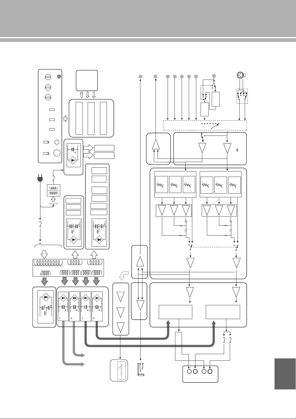
25 Fr
■ Schéma fonctionnel
CD
TUNER
LINE1
LINE2
LINE2 OUT
PHONO
INPUT SELECTOR
ATT.UINT1
PRE OUT
MAIN IN
MM//MC
FLOATING BALANCE
SPEAKER DRIVER
MOSFET
L CH
FLOATING POWER SUPPLY
FLOATING BALANCE
POWER AMPLIFIER
VOLUME
BALANCE GAIN SEL
MAIN
TRANSFORMER
INDEPENDENT REGULATED POWER SUPPLY (for AUDIO)
FOR
MC AMP
FOR
MM EQ AMP
FOR
After Vol Amp
FOR
Input Amp
FOR
VOLUME1 (Lch)
SUB TRANSFORMER
(REC)
VOLUMEINPUT
BALANCE BASS
CPU
CONTROL
PROTECTION
SPEAKER OUT
FRONT PANEL
SP A Lch
SP B Lch
BAL
ATT.UINT2
ATT.UINT3
ATT.UINT1
ATT.UINT2
ATT.UINT3
LOW IMPEDANCE DRIVE
HEADPHONE AMP.
HEAD PHONE
TRIGGER IN
BUFFER AMP
FLOATING BALANCE
SPEAKER DRIVER
MOSFET
TONE CONTROL
REC OUT BUFFER
POWER RELAY
L CH
L CH
R CH
R CH
RELAY
MOTOR VOL
FOR
VOLUME2 (Rch)
METER
IR IN
IR OUT
Standby power
CPU/LOGIC, etc.
METER
PHONES
TRIM
SPEAKERS
OFF/A/B/A+B
METER
OFF/PEAK/VU
PHONO
MM/MC
AUDIO MUTE
REAR PANEL
METER UNIT
HOT
(
+
)
COLD (-)
Phase change
(normal / inv.)
UNBALANCE
BALANCE
CONVERTER
BUFFER AMP
MC
HEAD AMP
MM EQ
AMP
PRE OUT BUFFER
POWER AMP PRE STAGE
HOT
(
+
)
COLD (-)
FLAT (DEFEAT)
FLAT (DEFEAT)
TONE CONTROL
METER CIRCUIT
To POWER AMP
R CH
Lo
g
am
p
lifie
r
Peak / VU DRIVER
A
B
+
–
+
–
TREBLE
IR
REMOTE
Français
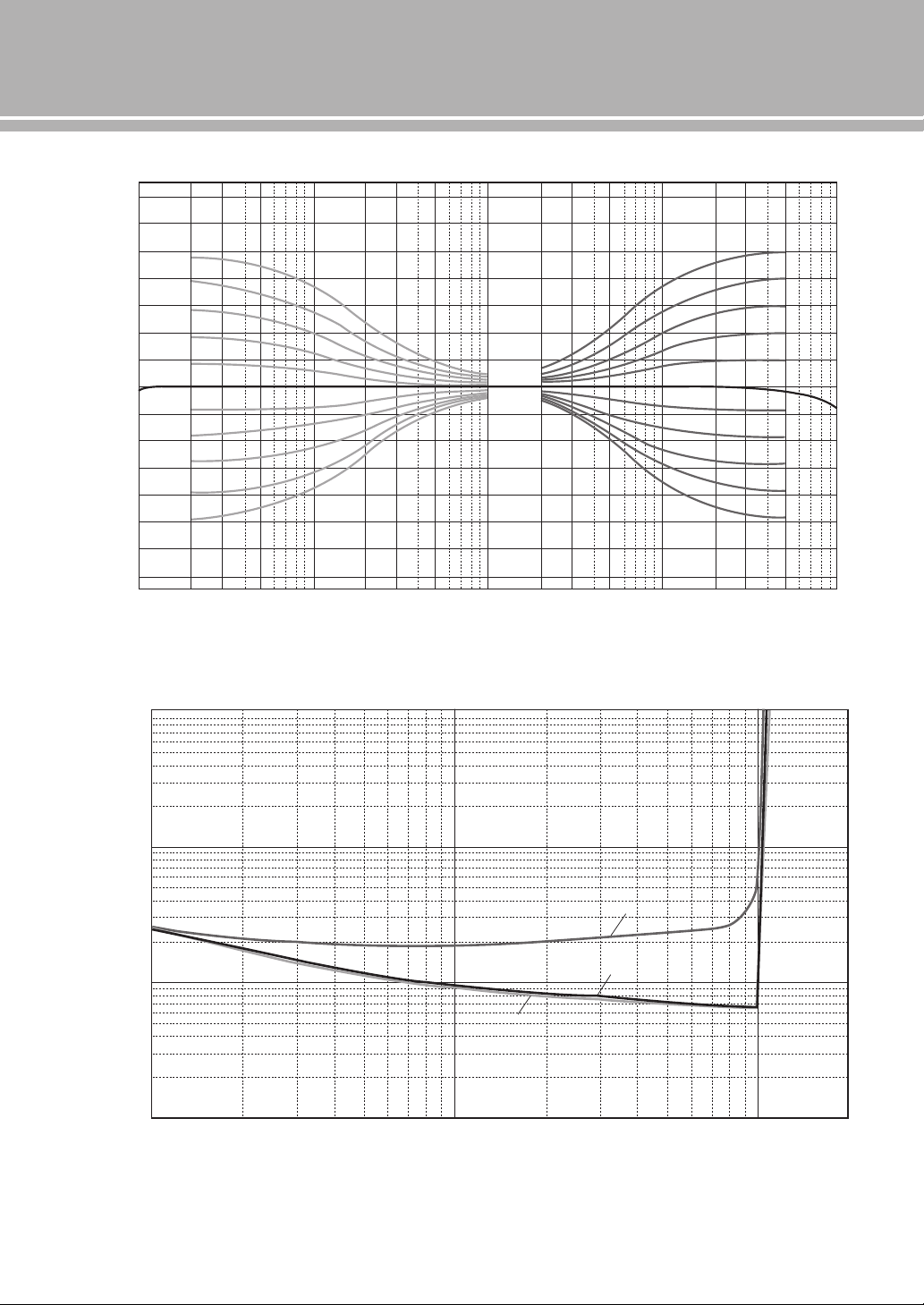
26 Fr
Caractéristiques techniques
■ Caractéristiques du contrôle du son
■ Distorsion harmonique totale
10 20 30 50 100 200 300 500 1k
Frequency (Hz)
Response (dB)
2k 3k 5k 10k 20k 30k 50k 100
k
–14
–12
–10
–8
–6
–4
–2
0
2
4
6
8
10
12
14
0.001
0.002
0.003
0.005
0.01
0.02
0.05
0.03
0.1
0.2
0.3
0.5
1
1056 8234 10050 60 8020 30 401
Measured (W)
THD + N Ratio (%)
20Hz
1kHz
20kHz
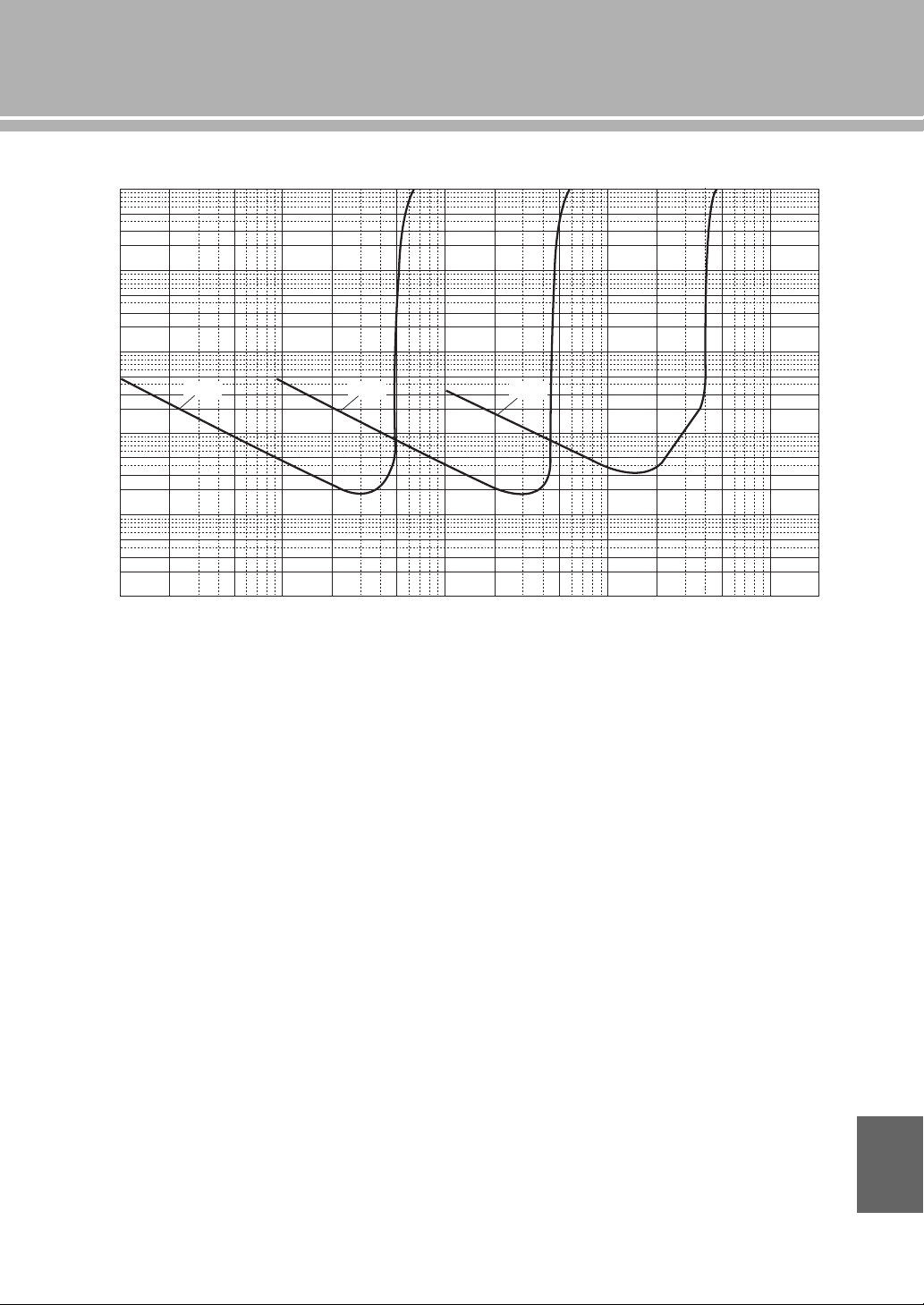
27 Fr
■ Distorsion harmonique totale (PHONO)
100µ 200µ 500µ 1m 2m 5m 10m 20m
Generator Level (Vrms)
50m 100m 200m 500m 1 2
20Hz 1kHz 20kHz
10
5
2
3
1
0.5
0.2
0.3
0.02
0.03
0.002
0.003
0.0002
0.0003
0.1
0.01
0.001
0.0001
0.05
0.005
0.0005
THD + N Ratio (%)
Français
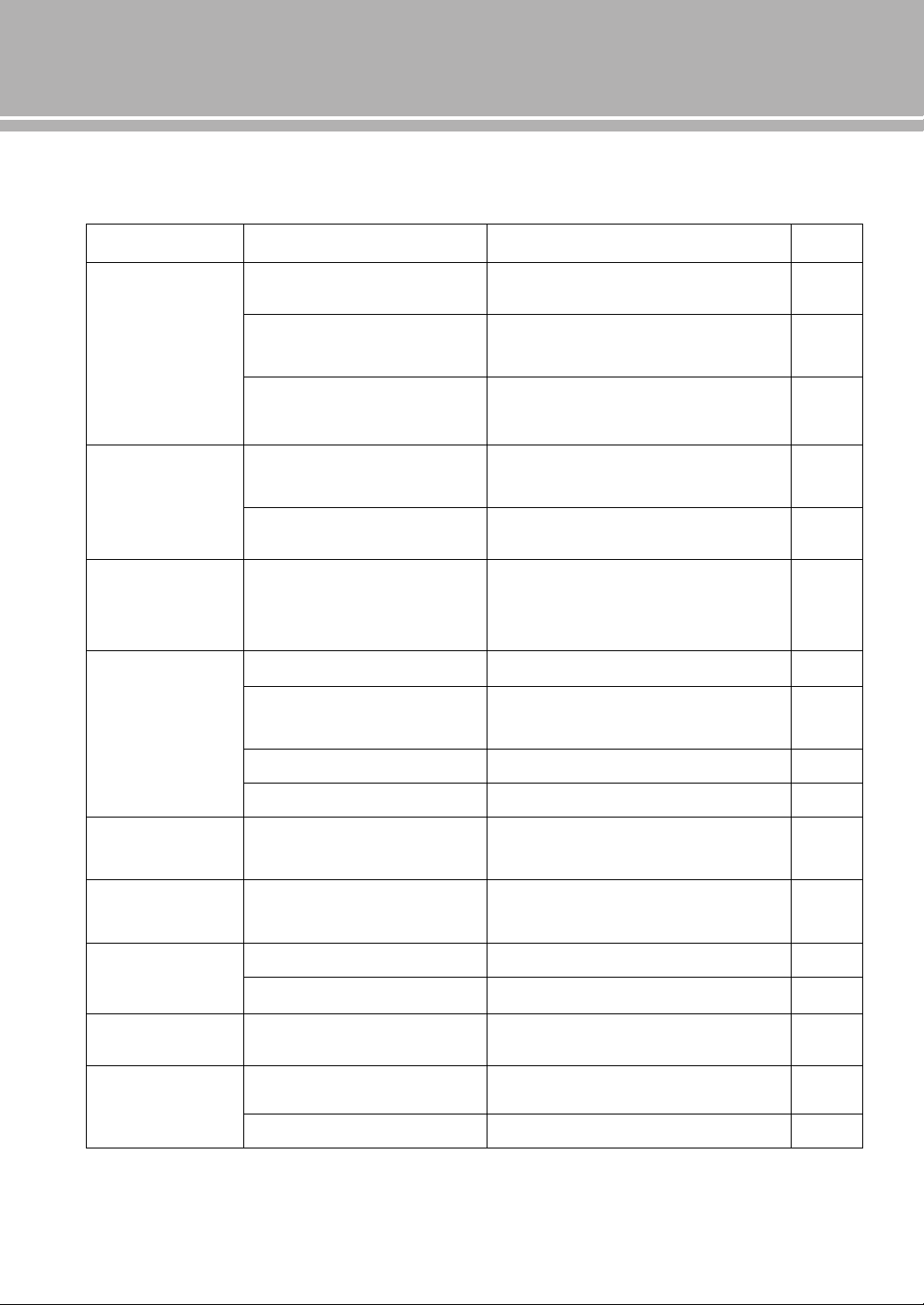
28 Fr
Guide de dépannage
Reportez-vous au tableau suivant si l’appareil ne fonctionne pas comme il devrait. Si l’anomalie constatée n’est pas
mentionnée, ou encore si les actions correctives suggérées sont sans effet, mettez l’appareil hors tension, débranchez le
câble d’alimentation et prenez contact avec le revendeur ou le service après-vente agréé Yamaha le plus proche.
Anomalies Causes possibles Actions correctives
Voir
page
L’appareil ne se met
pas sous tension.
Le câble d’alimentation n’est pas raccordé
à la prise AC IN du panneau arrière de
l’appareil ou à une prise secteur.
Branchez soigneusement le câble d’alimentation.
19
Le circuit de protection a été actionné du
fait de la présence d’un court-circuit, etc.
Assurez-vous que les câbles d’enceintes ne sont pas
en contact entre eux ou sont en court-circuit avec le
panneau arrière de cet appareil, et remettez cet
appareil sous tension.
18
L’appareil a été soumis à une secousse
électrique puissante (provoquée par
exemple par un orage ou une décharge
d’électricité statique).
Mettez l’appareil hors tension, débranchez le câble
d’alimentation, puis rebranchez-le environ 30
secondes plus tard et utilisez l’appareil comme à
l’accoutumée.
—
Le témoin STANDBY/
ON du panneau avant
clignote.
Le circuit de protection a été actionné du
fait de la présence d’un court-circuit, etc.
Assurez-vous que les câbles d’enceintes ne sont pas
en contact entre eux ou sont en court-circuit avec le
panneau arrière de cet appareil, et remettez cet
appareil sous tension.
18
Il y a un problème au niveau des circuits
internes de cet appareil.
Débranchez le câble d’alimentation et prenez contact
avec le revendeur ou le service après-vente agréé
Yamaha le plus proche.
—
Le témoin INPUT du
panneau avant
clignote et le volume
est réduit lors de la
mise sous tension de
cet appareil.
Le circuit de protection a été actionné du
fait de la présence d’un court-circuit, etc.
Assurez-vous que les câbles d’enceintes ne sont pas
en contact entre eux ou sont en court-circuit avec le
panneau arrière de cet appareil, et remettez cet
appareil sous tension.
18
Pas de son. Les raccordements des câbles d’entrée ou
de sortie ne sont pas corrects.
Branchez correctement les câbles. Si le problème
persiste, les câbles sont sans doute défectueux.
16
Aucune source d’entrée convenable n’a
été sélectionnée.
Sélectionnez la source d’entrée souhaitée avec le
sélecteur INPUT du panneau avant (ou avec l’une des
touches de sélection d’entrée du boîtier de
télécommande).
8, 12
Le sélecteur SPEAKERS est réglé sur
OFF.
Réglez le sélecteur SPEAKERS sur la position
appropriée.
7
Les raccordements des enceintes sont
défectueux.
Corrigez les raccordements.
18
Les sons
disparaissent
brusquement.
Le circuit de protection a été actionné du
fait de la présence d’un court-circuit, etc.
Assurez-vous que les câbles d’enceintes ne sont pas
en contact entre eux ou sont en court-circuit avec le
panneau arrière de cet appareil, et remettez cet
appareil sous tension.
18
Le niveau sonore ne
peut pas être réglé.
MAIN DIRECT est sélectionné comme
source d’entrée.
Réglez le volume sur le composant raccordé. Vous
pouvez également raccorder le composant externe
aux prises d’entrée autres que MAIN IN et
sélectionner la source d’entrée correspondante.
8, 9
Seule l’enceinte de
gauche ou de droite
émet des sons.
Les raccordements des câbles sont
incorrects.
Branchez correctement les câbles. Si le problème
persiste, les câbles sont sans doute défectueux.
16
Mauvais réglage de la commande
BALANCE.
Réglez la commande BALANCE sur la position
appropriée.
7
Basses insuffisantes
et absence
d’ambiance.
Les fils + et – sont inversés sur
l’amplificateur ou les enceintes.
Raccordez les fils d’enceintes en respectant la phase
+ et –.
16
Un « ronflement » est
audible.
Les raccordements des câbles sont
incorrects.
Branchez à fond les fiches du câble audio. Si le
problème persiste, les câbles sont sans doute
défectueux.
16
Pas de raccordement du tourne-disque à la
borne GND.
Branchez le tourne-disque à la borne GND de cet
appareil.
16
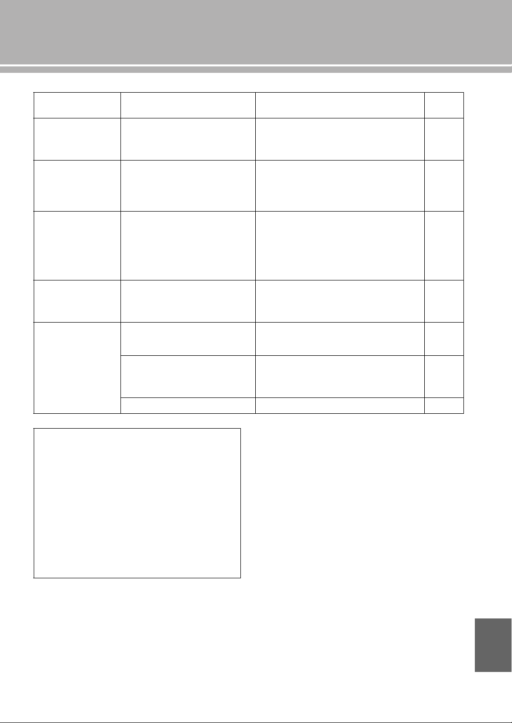
29 Fr
Anomalies Causes possibles Actions correctives
Voir
page
Le son du composant
branché à la prise
BAL est de moins
bonne qualité.
Le niveau sonore est plus élevé que le
niveau d’entrée maximal des prises
d’entrée symétriques XLR.
Si le niveau de sortie de l’appareil connecté est deux
fois trop élevé, réglez le sélecteur ATTENUATOR
situé au-dessus des prises d’entrée sur la position
ATT. ( –6 dB).
20
Les basses ne sont
pas spatiales lorsque
BAL (entrée
symétrique) est
sélectionné.
La polarité est incorrecte. Sélectionnez la polarité correcte avec le sélecteur
PHASE.
20
Le son est de moins
bonne qualité lorsque
vous écoutez avec un
casque raccordé au
lecteur de CD
raccordé à cet
appareil.
L’appareil est hors service. Mettez l’appareil sous tension.
—
Le niveau sonore est
trop faible pendant
l’écoute d’un
microsillon.
Mauvais réglage du commutateur
PHONO sur le panneau avant.
Mettez le commutateur PHONO sur la position MM
ou MC selon le type de cartouche magnétique du
tourne-disque.
9
Le boîtier de
télécommande ne
fonctionne pas ou
n’agit pas
convenablement.
La portée et l’angle sont incorrects. Le boîtier de télécommande agit à une distance
inférieure à 6 m et sous un angle inférieur à 30 degrés
par rapport à une perpendiculaire à la face avant.
14
Le lumière directe du soleil ou d’un
éclairage (lampe fluorescente à
convertisseur, etc.) frappe le capteur de
télécommande de cet appareil.
Changez l’emplacement de l’appareil.
8
Les piles sont usagées. Remplacez les piles.
14
Entretien de cet appareil
Finition brillante sur les panneaux latéraux
L’utilisation du chiffon Yamaha Unicon (disponible en
option) est recommandée. Pour enlever les taches rebelles,
utilisez le Yamaha Piano Unicon (disponible en option). Pour
l’achat, contactez le revendeur ou le service après-vente agréé
Yamaha le plus proche.
Autre finition
Pour essuyer cet appareil, n’utilisez pas de solvants chimiques
(alcool, diluant, etc.) qui risqueraient d’endommager la
finition. Utilisez un chiffon propre et sec. Pour enlever les
taches rebelles, trempez un chiffon doux dans un mélange de
détergent et d’eau et extrayez bien toute l’eau du chiffon avant
de nettoyer l’appareil.
Français


© 2014 Yamaha Corporation
U
Printed in Malaysia VAA8450
Integrated Amplifier
Amplificateur Intégré
OWNER’S MANUAL
MODE D’EMPLOI