Loading ...
Loading ...
Loading ...
PQ2071-en-GB_V1.3 7/15
8
AC Voltage Measurements
AC voltage on Main Display (Frequency on Secondary Display)
The AC Voltage ranges are: 100V, 400V and 750V
The frequency range is: 50Hz~60Hz
Single phase - connect the L1 test lead to the
power wire and connect the COM lead to the
neutral wire.
3-Phase 4-wire - connect the COM lead to the
neutral conductor.
3-Phase 3-Wire - connect the COM lead to an
earth ground.
1. Insert the black test lead into the meter’s
COM input terminal.
2. Connect the other end of the black
(COM) test lead to the corresponding
neutral wire (single phase and 3P4W) or
for a 3P3W to one of the phase wires.
3. Single phase: Insert a test lead into L1
and connect it to the Power wire.
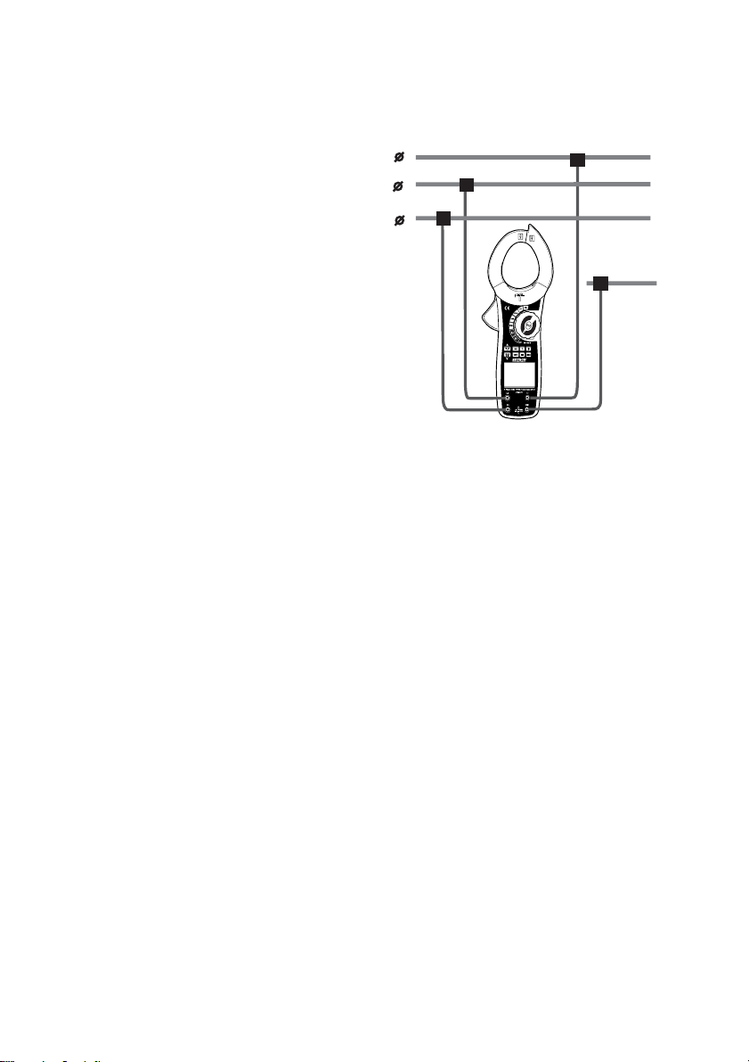
3Φ4Wire: Connect all 3 leads (red -L1), yellow-
L2, and blue-L3) into the L1, L2, & L3 meter
input terminals and connect each to a corresponding phase wire. (see fig 5)
3Φ3Wire: Connect L1 and L3 to the meter and then connect L1 to one phase wire and L3 to
the remaining phase wire.
4. Turn the rotary function switch to the VAC position to select Voltage + Frequency mode.
5. Press the L1-L2-L3 button to select the appropriate phase, the display shows the
corresponding phase symbol on the display. L1 is the first (single) phase, L2 is the second
phase, and L3 is the third phase.
6. The main display indicates the True RMS voltage and the secondary display indicates the
Frequency value.
7. To monitor the highest (MAX) and lowest (MIN) readings, press the MAX-MIN button. The
LCD will now display ‘MAX’ and the meter will indicate only the maximum AC voltage True
RMS value.
8. Press MAX-MIN again and the LCD will display ‘MIN’ and the meter will indicate only the
minimum AC voltage True RMS value.
9. Press MAX-MIN again to exit the MAX-MIN mode and return to displaying the real-time AC
voltage True RMS value.
10. The display indicates ‘OL’ when the input voltage is greater than 750V rms.
Note: When the measurement session has been completed, disconnect the test leads from the
circuit under test and remove the test leads from the meter’s input terminals.
L1
COM
L2
L3
2
1
3
COM
Figure 5 (3P4W)
Loading ...
Loading ...
Loading ...