Loading ...
Loading ...
Loading ...
PQ2071-en-GB_V1.3 7/15
13
3-Phase, 3-Wire Power Power Measurements
Note:
When measuring 3 phase / 3-wire systems, hold down the L1-L2-L3 button for 5 seconds to display
the 3ϕ3w icon. (Press and hold the L1-L2-L3 button again for 5 seconds to exit the 3 phase/3-wire
mode back to the default 3Φ4wire mode).
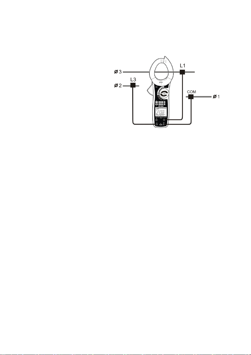
Connect the Meter as shown in Figure 10.
1. Insert the Red (L1) and Blue (L3) test leads into the L1, L3 meter input terminals and connect
these to 2 separate phases of the circuit under test as shown in Figure 10.
2. Insert the black test lead into the COM input terminal on the meter and connect it to the last
remaining wire of the 3 phase 3-wire system under test.
Note Skip the second (L2) connection.
3. Set the Rotary switch to the KW position.
4. Press the L1-L2-L3 button to choose the first phase L1 (see figure 8). The primary display
shows the kW for phase L1 and the secondary display shows the Phase angle (PG).
5. Press the ∑ button to save and sum the measured value for L1. (see Figure 8)
6. Move the clamp jaw to the power conductor connected to the L3 voltage test lead.
7. Press the L1-L2-L3 button to choose the first phase L3. The primary display shows the kW for
phase L3 and the secondary display shows the Phase angle (PG).
8. Press the ∑ button to save and sum the measured value for L3. (figure 8)
9. After recording the kW power measurement value for the L3 phase, press and Hold the
∑ button for 1 second to display the 3 phase sum of kW on the main display and kVA on the
secondary display. (figure 9)
10. Press the ▲ button to display the 3 phase sum of kVAR on the main display.
11. Press and Hold the ∑ button for 1 second to return to normal operation
For Figure 9: for 3-wire ∑W = W1 + W3
Figure 10
Loading ...
Loading ...
Loading ...