Loading ...
Loading ...
Loading ...
4
2. PREPARE INSTALLATION
WARNING
!
When performing installation, servicing or cleaning the unit, it is recommended to wear safety glasses and gloves.
NOTE: Before proceeding to the installation, check the contents of the box. If items are missing or damaged, contact the manufacturer.
Make sure that the following items are included:
– Hood
– Accessories
• Decorative flue assembly (lower and upper flues)
• 2 Hybrid filters
• 1 Ceiling mounting bracket (screwed on top of the hood)
• 8 Angle brackets
• 8” Round adapter/damper (in a separate box)
• Bag of parts (taped on the blower box) including: 2 wire connectors, 1 wire clamp, 8 no. 10 x 1½” wood screws,
8 steel washers, 10 no. 8 x 3/8” quadrex screws, 17 no. 10-32 flanged locknuts, 50 x 10-32 x 1/2” quadrex hex head screws,
2 no. 8 x 1/2” low profile Phillips screws, 2 no. 8 x 1/2” quadrex black screws.
Parts sold separately:
– Ducts, elbows, wall and roof caps.
– Optional flue extension for 10-ft. ceilings model no. AEICB3SB (stainless steel) or no. AEICB3BLS (black stainless steel).
– Optional remote control (model no. ACR3).
– Glass panels for ICB3I36SBN model (see replacement parts list).
NOTE: During installation, protect countertop and/or cooktop.
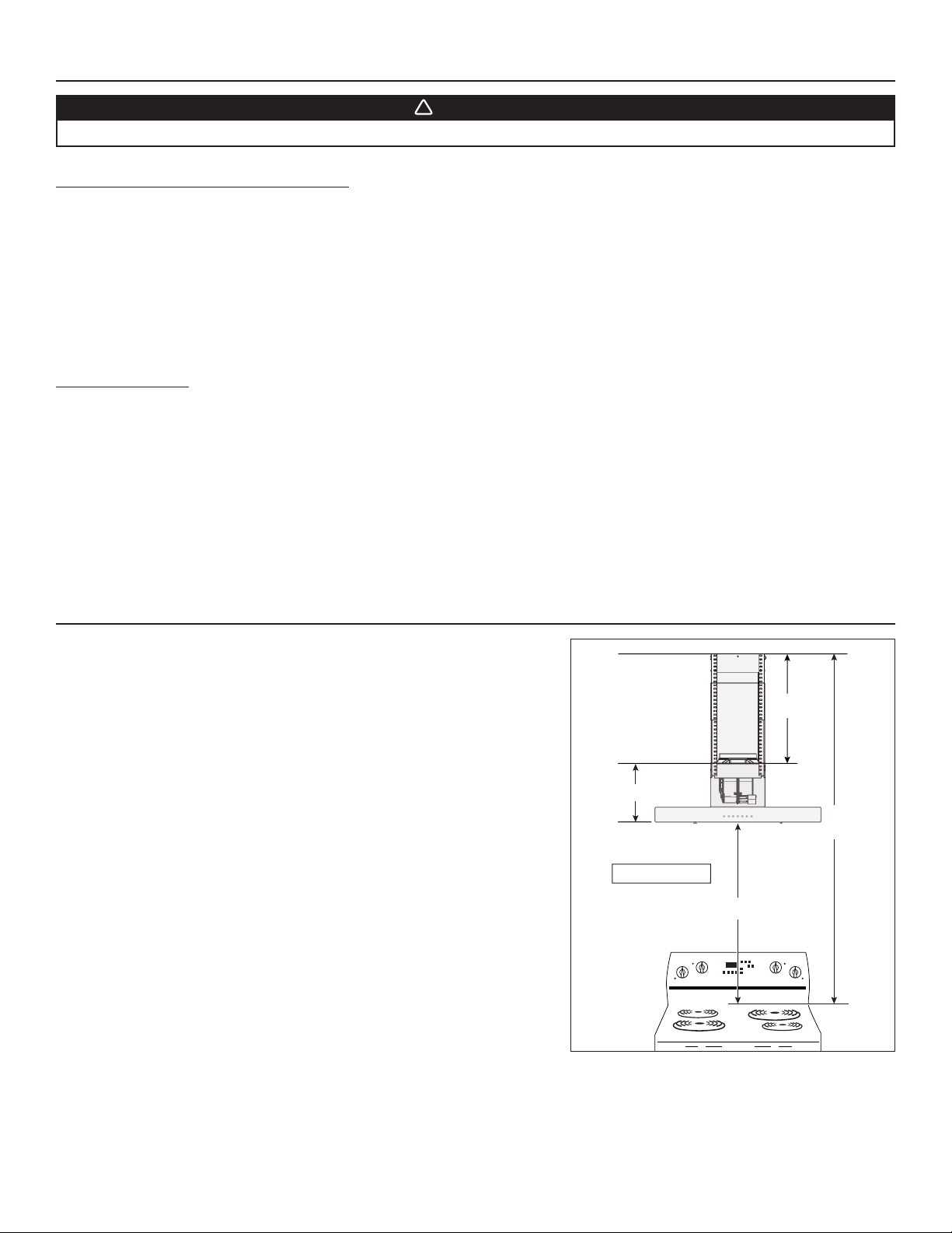
3. MEASURE INSTALLATION
HH0157A
C
B
A
CEILING
COOKTOP
BLOWER
BOX
TOP
12
3
⁄16"
C = B - A - 12
3
⁄16"
RANGE
HOOD
BOTTOM
Determine the required distance between the ceiling and the top of the blower
box (C) based upon ceiling height (B) and desired height of hood above cooktop (A).
NOTE: C = B - A - 12 3/16”
Loading ...
Loading ...
Loading ...