Loading ...
Loading ...
Loading ...
6 • English PowerSpace P2600A/P21000A/P4300A • Installation Guide
PRO.BOSE.COM
Installation
Setting Up a PowerSpace Amplifier
1. Starting with the amplifier power O, set the rear-panel switches as needed for the application. Then make all required power and
audio connections.
2. Press the Power switch on the front panel to power the amplifier On.
3. Depending on the loudspeakers you are configuring with your PowerSpace amplifier, do one of the following:
A. If all outputs are set to drive 70/100V high-impedance loudspeakers, rotate each corresponding Output Attenuation control to
0 dB attenuation. Set each loudspeaker tap to the appropriate setting. Based on the total loudspeaker tap settings, the amplifier
will deliver the required power to each output, up to the rated channel power. For examples, see the PowerSpace Application
Guide at PRO.BOSE.COM.
B. If all outputs are set to drive 4–8 low-impedance loudspeakers, rotate each Output Attenuation control until the desired levels
are reached. Play a signal containing the highest normal program or pink noise input level. Ensure the material is near the input
sensitivity for best noise performance. Observe the Output Limit LED for the output being adjusted. If the signal level is higher
than the protection limit for the loudspeaker, the Output Limit LED will light amber. Increase the attenuation until the Output
Limit LED does not light, or only occasionally lights. For examples, see the PowerSpace Application Guide at PRO.BOSE.COM.
4. Since each output is configurable to drive either high-impedance or low-impedance loudspeakers, the amplifier can support mixed-
impedance installations. In this setup, first configure the high-impedance channels before configuring the low-impedance channels.
5. When setting up the amplifier, monitor the Input Signal LEDs for input clipping and the Output Limit LEDs for output limiting to
ensure the amplifier is working within proper operating conditions. Make adjustments if necessary.
Technical Considerations:
Adjusting the Output Attenuation control of a single channel does not aect the level of other channels. Each channel will limit to its rated
power. If the continuous power demand remains too high, the amplifier will gradually limit to an average of ⅓ power continuously.
There are multiple ways to adjust output power in a PowerSpace amplifier application:
• Adjust input signal level relative to the sensitivity setting of the amplifier.
• Adjust the Output Attenuation controls of the amplifier.
• Adjust the transformer tap settings of any connected high-impedance loudspeakers.
Setup Placement
CAUTION: This product is not intended for installation or use in indoor water facility areas (including, without limitation, indoor
pools, indoor water parks, hot tub rooms, saunas, steam rooms and indoor skating rinks).
CAUTION: Do not mount the product in locations where condensation may occur.
Importance of Proper Ventilation
For placement of the amplifier, keep the following in mind:
• Make sure that air can circulate freely from front to back for adequate ventilation. There are vents on the front, back, and sides of the
amplifier.
• Do not cover or block amplifier vents.
• Make sure the chassis is protected from heat and kept away from direct heat sources, such as heating vents and radiators.
CAUTION: Due to ventilation requirements, do not place the product in a confined space such as in a wall cavity or in an enclosed
cabinet. Do not allow the chassis to exceed the maximum operating temperature of 40 °C (104 °F). Be aware of conditions in an
enclosed rack that may increase the temperature above room-ambient conditions. If the amplifier becomes too hot, it will go into a
thermal protection mode and mute all outputs.
Rack Mounting
PowerSpace amplifiers are designed to fit standard 48-centimeter (19-inch) rack equipment, occupying one rack-unit (RU) in height
(4.4cm/1.7 in), requiring a mounting depth of 40.6 centimeters (16.0 inches) from the front rack rail. Use four fasteners with washers (not
supplied) to mount the amplifier front panel rack ears to the equipment rack rails.
CAUTION: Only use the mounting hardware recommended by the rack manufacturer.
CAUTION: Do not place or install the bracket or product near any heat sources, such as fireplaces, radiators, heat registers or other
apparatus (including amplifiers) that produce heat.
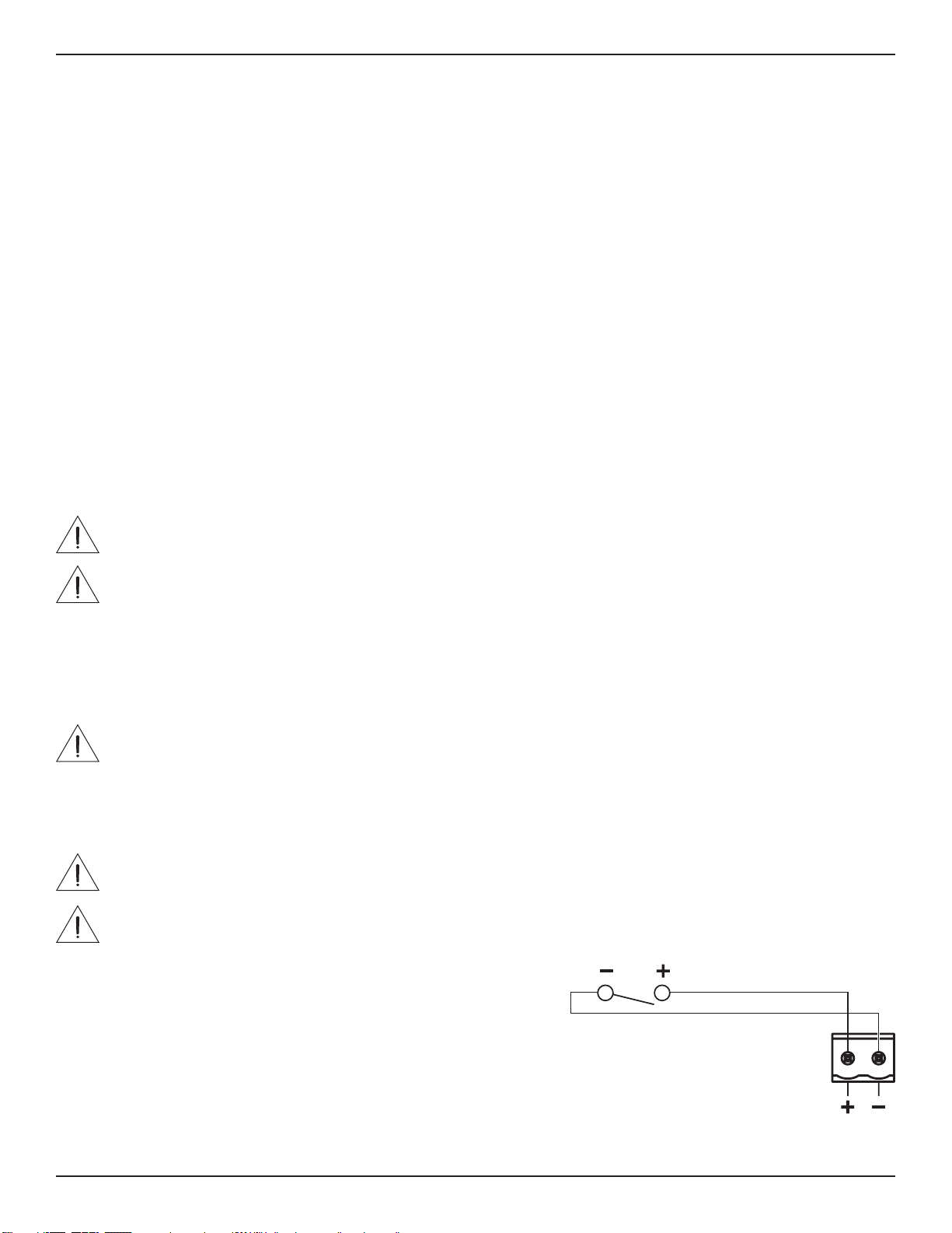
Mute with Standard Contact Closure
The amplifier is designed to mute all outputs either when the Mute contacts
are shorted together, or when the Mute contacts are opened, depending on the
amplifier configuration. The default state is Normally Open (NO), where a short
across the Mute connector will mute all outputs. You can use the Mute DIP switch
to invert the mute polarity to Normally Closed (NC), where an open circuit across
the Mute connector will mute all outputs.
Note: All Output Limit LEDs will blink red when the amplifier is muted from the
rear panel Mute connector.
Loading ...
Loading ...
Loading ...