Loading ...
Loading ...
Loading ...
20 | English
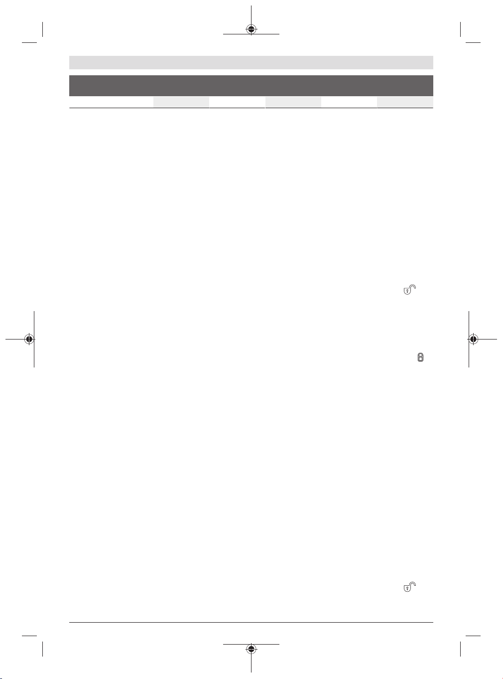
UniversalImpact
800
UniversalImpact
6700
UniversalImpact
7000
UniversalImpact
8000
K m/s
2
1.5 1.5 1.5 1.5
The vibration level and noise emission value given in these
instructions have been measured in accordance with a
standardised measuring procedure and may be used to com-
pare power tools. They may also be used for a preliminary
estimation of vibration and noise emissions.
The stated vibration level and noise emission value repres-
ent the main applications of the power tool. However, if the
power tool is used for other applications, with different ap-
plication tools or is poorly maintained, the vibration level
and noise emission value may differ. This may significantly
increase the vibration and noise emissions over the total
working period.
To estimate vibration and noise emissions accurately, the
times when the tool is switched off or when it is running but
not actually being used should also be taken into account.
This may significantly reduce vibration and noise emissions
over the total working period.
Implement additional safety measures to protect the oper-
ator from the effects of vibration, such as servicing the
power tool and application tools, keeping their hands warm,
and organising workflows correctly.
Assembly
u Pull the plug out of the socket before carrying out any
work on the power tool.
Auxiliary Handle (seefigureA)
u Before carrying out any work, make sure that the wing
bolt is tightened. Loss of control can cause personal in-
jury.
u Do not operate your power tool without the auxiliary
handle (20).
Turn the wing bolt (21) anti-clockwise and guide the auxili-
ary handle (9) in the required position over the drill chuck
onto the spindle collar of the power tool.
You can swivel the auxiliary handle (20) in order to achieve a
safe work posture that minimises your fatigue.
Swivel the auxiliary handle (20) to the required position and
retighten the wing bolt (21) in clockwise direction.
Setting the Drilling Depth (seefigureB)
You can use the depth stop(23) to set the required drilling
depth X.
Press the button for depth stop adjustment (22) and insert
the depth stop into the auxiliary handle (9).
The fluting on the depth stop (23) must face downwards.
Pull the depth stop far enough out that the distance between
the drill bit tip and the edge of the depth stop corresponds
to the required drilling depth X.
Drill Assistant
Applying the Drill Assistant (seefiguresC–D)
The Drill Assistant(10) can be used with and without the
dust collection device(13). Use of the dust collection
device(13) is limited to drill bits with a diameter of 12 mm
and a length of 120 mm.
Attach the dust collection device(13) to the adapter(26).
Press the unlocking button(8) to release the Drill Assist-
ant(10) from its parked position.
Guide the Drill Assistant(10) over the drill chuck onto the
spindle collar of the power tool.
Lock it by turning the wing bolt(18) clockwise.
Setting the Drilling Depth (seefiguresE–F)
Attach the drill bit (see section "Changing the Tool").
You can use the setting ring(17) to set the required drilling
depthX.
Unlock the setting ring(17) by turning it to the left .
Place the dust container(11) or the adapter(26) flush
against the wall or workpiece. Move the tip of the drill bit to
the wall or workpiece.
Slide the setting ring(17) backwards until the distance
matches the required drilling depthX or place a wall plug on
the rail and slide the setting ring(17) backwards to the wall
plug. Lock the setting ring(17) by turning it to the right .
Take the wall plug out of the rail again. The drilling depth now
matches the set length X on the rail.
Note: It is important to have the exact drilling depth when
using wall plugs. If the drilled hole is too deep, the wall plug
will slip too far into the wall or workpiece. If the hole is too
small, the wall plug will stick out.
Emptying the dust container (see figure G)
The dust container(11) is enough for drilling about 25 holes
in masonry at a drilling depth of 30 mm with a drill bit dia-
meter of 6 mm.
To remove the dust container(11), press the side-mounted
unlocking buttons(12) and pull the dust container off down-
wards.
Empty the dust container(11) and reinsert it (until it can be
heard to engage).
Removing the Drill Assistant
Press and hold the clip(16) of the dust collection
device(13) and pull the dust collection device(13) off to-
wards the front.
Turn the wing bolt(18) anticlockwise until the auxiliary
handle(9) can be moved and pull the auxiliary handle(9) off
the power tool.
Unlock the setting ring(17) by turning it to the left .
Hold the auxiliary handle(9) in place and slide the rail to-
wards the auxiliary handle until it can be heard to engage.
1 609 92A 57D | (29.11.2019) Bosch Power Tools
Loading ...
Loading ...
Loading ...