Before using your new product, please read these instructions to prevent any damage.
ASSEMBLY GUIDE
58" TV Gaming Stand
NS-HF2007

www.insigniaproducts.com
2
Contents
IMPORTANT SAFEGUARDS . . . . . . . . . . . . . . . . . . . . . . . . . . . . . . . . . . . . . . . . . . . . . . . . . . . . . . . . . . . . . . . . . . . . . . . . . . . . 2
Features . . . . . . . . . . . . . . . . . . . . . . . . . . . . . . . . . . . . . . . . . . . . . . . . . . . . . . . . . . . . . . . . . . . . . . . . . . . . . . . . . . . . . . . . . . . . . . 3
Dimensions. . . . . . . . . . . . . . . . . . . . . . . . . . . . . . . . . . . . . . . . . . . . . . . . . . . . . . . . . . . . . . . . . . . . . . . . . . . . . . . . . . . . . . . . . . . . . . . . . . . . . . . 3
Maximum weights . . . . . . . . . . . . . . . . . . . . . . . . . . . . . . . . . . . . . . . . . . . . . . . . . . . . . . . . . . . . . . . . . . . . . . . . . . . . . . . . . . . . . . . . . . . . . . . . 4
Package contents . . . . . . . . . . . . . . . . . . . . . . . . . . . . . . . . . . . . . . . . . . . . . . . . . . . . . . . . . . . . . . . . . . . . . . . . . . . . . . . . . . . . . 5
Parts . . . . . . . . . . . . . . . . . . . . . . . . . . . . . . . . . . . . . . . . . . . . . . . . . . . . . . . . . . . . . . . . . . . . . . . . . . . . . . . . . . . . . . . . . . . . . . . . . . . . . . . . . . . . . 5
Hardware. . . . . . . . . . . . . . . . . . . . . . . . . . . . . . . . . . . . . . . . . . . . . . . . . . . . . . . . . . . . . . . . . . . . . . . . . . . . . . . . . . . . . . . . . . . . . . . . . . . . . . . . . 6
Needed tool . . . . . . . . . . . . . . . . . . . . . . . . . . . . . . . . . . . . . . . . . . . . . . . . . . . . . . . . . . . . . . . . . . . . . . . . . . . . . . . . . . . . . . . . . . . . . . . . . . . . . . 7
Assembly instructions. . . . . . . . . . . . . . . . . . . . . . . . . . . . . . . . . . . . . . . . . . . . . . . . . . . . . . . . . . . . . . . . . . . . . . . . . . . . . . . . . 7
Maintaining your TV stand . . . . . . . . . . . . . . . . . . . . . . . . . . . . . . . . . . . . . . . . . . . . . . . . . . . . . . . . . . . . . . . . . . . . . . . . . . .50
Specifications. . . . . . . . . . . . . . . . . . . . . . . . . . . . . . . . . . . . . . . . . . . . . . . . . . . . . . . . . . . . . . . . . . . . . . . . . . . . . . . . . . . . . . . .50
ONE-YEAR LIMITED WARRANTY . . . . . . . . . . . . . . . . . . . . . . . . . . . . . . . . . . . . . . . . . . . . . . . . . . . . . . . . . . . . . . . . . . . . . .51
IMPORTANT SAFEGUARDS
Please read and understand this entire manual before attempting to assemble, operate or install the product.
WARNING
CAUTION
• Before assembly and/or installation, carefully unwrap all parts.
• Locate and set aside the hardware kit before discarding packaging.
• Use care when assembling your new product. Take your time and follow assembly instructions closely.
WARNINGS
• For use with televisions weighting 60 lbs (27.3 kg) or less. Use with heavier televisions may causing tip over resulting in
death or serious injury.
• Death or serious injury may occur when children climb on audio and/or video equipment furniture. A remote control
or toys placed on the furnishing may encourage a child to climb on the furnishing and as a result the furnishing may tip
over on to the child.
• Risk or death or serious injury. This surface must be placed against a fixed in place wall at least as tall as the television.
• Relocating audio and/or video equipment to furniture not specifically designed to support audio and/or video
equipment may result in death or serious injury due to the furnishing collapsing or over turning onto a child.
SAVE THESE INSTRUCTIONS
Some steps are
more easily
handled with two

www.insigniaproducts.com
3
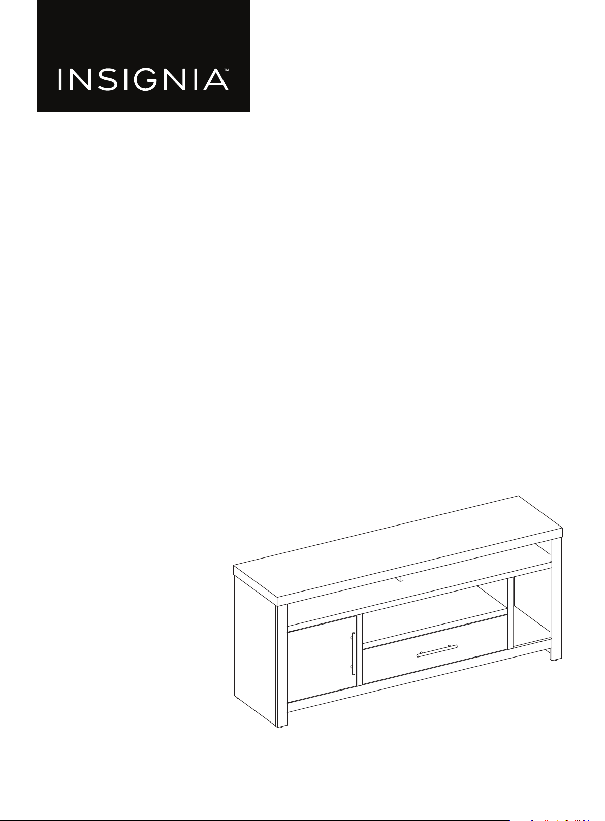
Features
• Supports 65 in. (165 cm) TVs up to 60 lbs. (27.2 kg)
• Multiple shelves provide a surplus of storage options for your game console, Blue-ray player, cable box, and speakers
• Specially designated space allows for vertical-standing game consoles
• Lower drawer stores remotes, controllers, cables, and more
• Cabinet door hides your entertainment accessories for clutter-free organization
• Adjustable horizontal shelf makes space for DVD and video game cases
• Tasteful gray woodgrain texture looks great in any space
Dimensions
25.4 in.
(64.5 cm)
1
5
.
5
i
n
.
(
3
9
.
4
c
m
)
58
in.
(
14
7.
3
c
m
)
29.
3
i
n
.
(
74.
4
c
m
)
5.9 in.
(15 cm)
5
4
i
n
.
(
1
3
7
.
2
c
m
)
7
.
9
i
n
.
(
2
1
.
1
c
m
)
13.6 in. (34.5 cm)
1
4
.
8
i
n
.
(
3
7
.
6
c
m
)
4.4 in. (11.2 cm)
www.insigniaproducts.com
4
58" TV Gaming Stand
Maximum weights
WARNING: You can use most flat panel televisions weighing 60 lbs. (27.3 kg) or less. Using televisions or weights heavier than the
maximums can result in instability that can cause tip-overs resulting in death or serious injury.
5 lbs. (6.8 kg)
30 lbs.
(13.6 kg)
60 lbs.
(27.3 kg)
TV size: 61"
(155 cm)
20 lbs. (9.1 kg) 60 lbs. (27.3 kg)
20 lbs. (9.1 kg)
www.insigniaproducts.com
5
Package contents
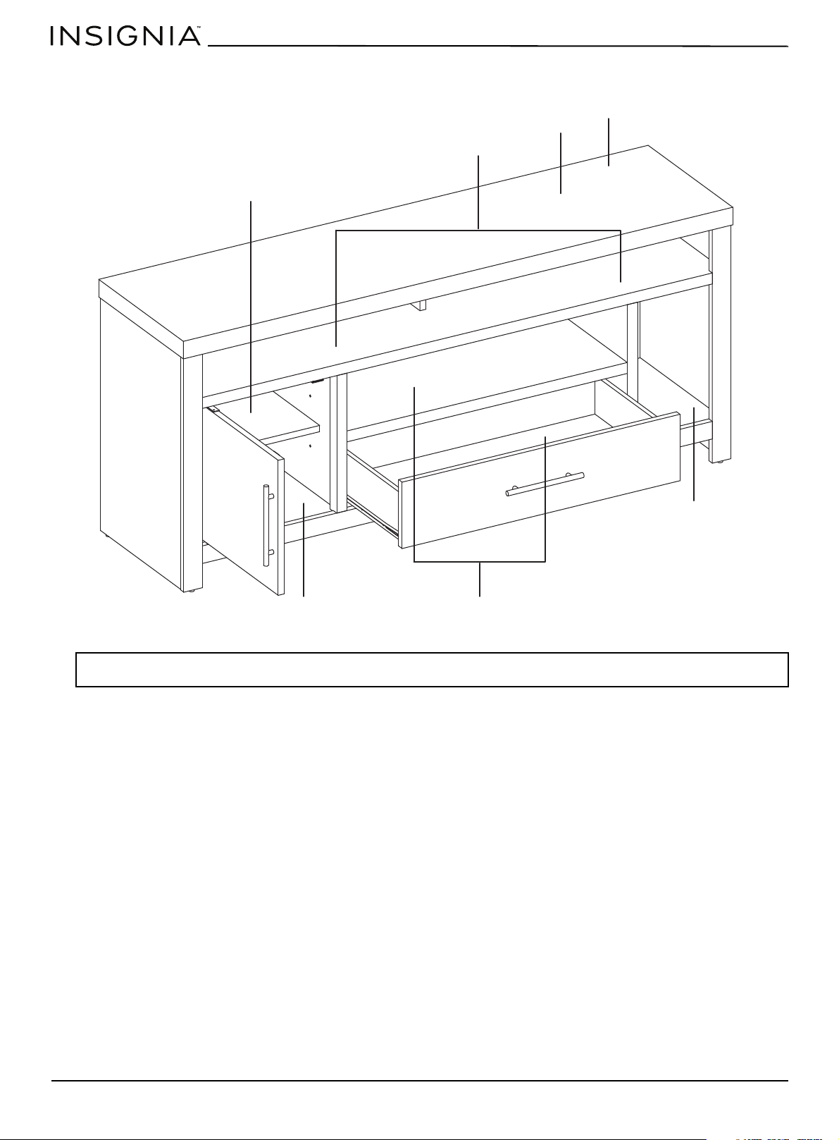
Parts
A Base (1)
B Left divider
panel (1)
C Right divider
panel (1)
D Long lower shelf (1)
E Upper shelf (1)
F Front edge (1)
G Top (1)
H Lower support (1)
I Left side
support (1)
J Right side
support (1)
K Left side (1)
L Right side (1)
M Lower back panel (1)
N Door (1)
O Short upper shelf
(1)
P Left drawer
side (1)
Q Right drawer
side (1)
R Drawer back (1)
S Drawer bottom (1)
T Drawer
support (1)
U Drawer front (1)
V Upper back panel (1)
Y Small divider
panel(1)
www.insigniaproducts.com
6
58" TV Gaming Stand
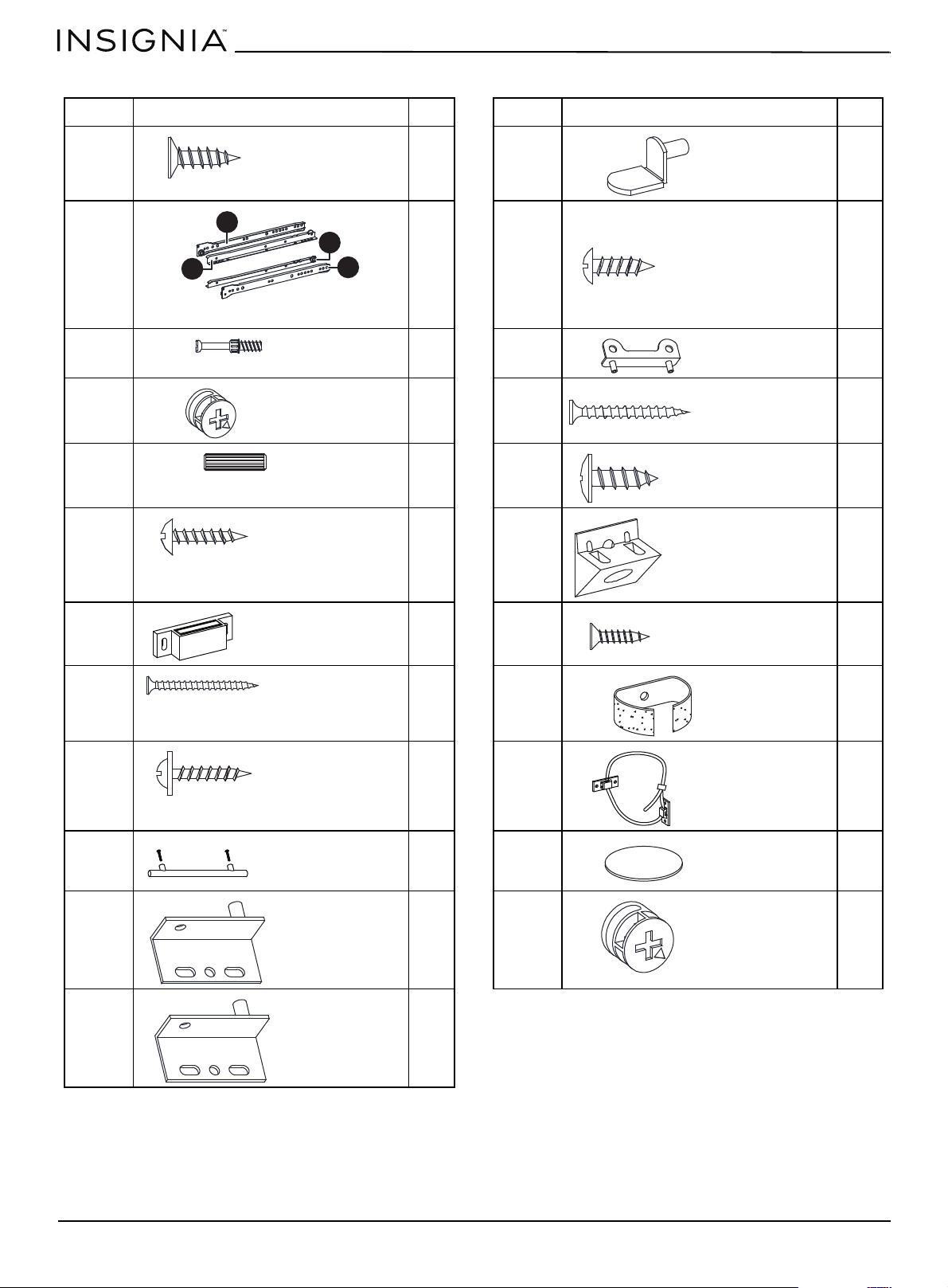
Hardware
LABEL STAND PART QTY. LABEL STAND PART QTY.
AA 12 MM 4
BB 1 set NN 4
CC 42 OO 2
DD 40 PP 6
EE 44 QQ 4
FF 6 RR 12
GG 1 SS 12
HH 6 TT 2
II 6 UU 2
JJ 2 VV 14
KK 1 WW 2
LL 1
3 × 12 mm screw
Shelf support
CR
DR
DL
CL
Left and right rail assembly
3.5 × 12 mm screw
Cam screw
Drawer support
Small cam lock
4 × 38 mm screw
Dowel
4.5 × 14 mm screw
3 × 15 mm screw
Back support bracket
Magnetic door latch
3.5 × 16 mm screw
4 × 50 mm screw
Cable wrap
3 × 16 mm screw
Anti-tip bracket
with plastic strap
Handle with screws
Cam lock cover
Lower hinge pin
Large cam lock
Upper hinge pin
www.insigniaproducts.com
7
Needed tool
Assembly instructions
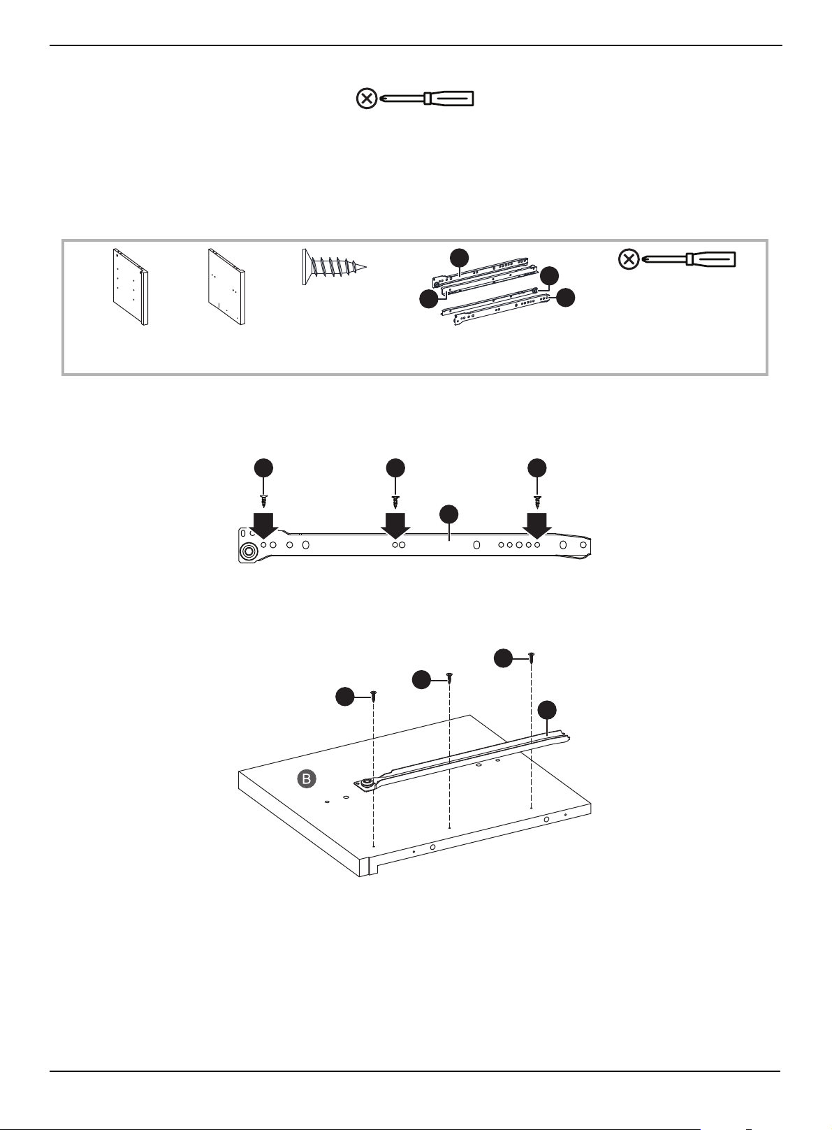
STEP 1:
You need:
1 Separate the CL and CR parts of the rail assembly (BB) from the DL and DR parts and set the DL and DR parts aside for
use in another step.
2 Insert three 3 × 12 mm screws (AA) into the correct holes on the CL and CR parts of the rail assembly (BB).
3 Align the CL part of the rail assembly (BB) to the inside of the left divider panel (B). Make sure that the wheel on the
assembly is at the back of the panel.
4 Tighten the screws with a Phillips screwdriver.
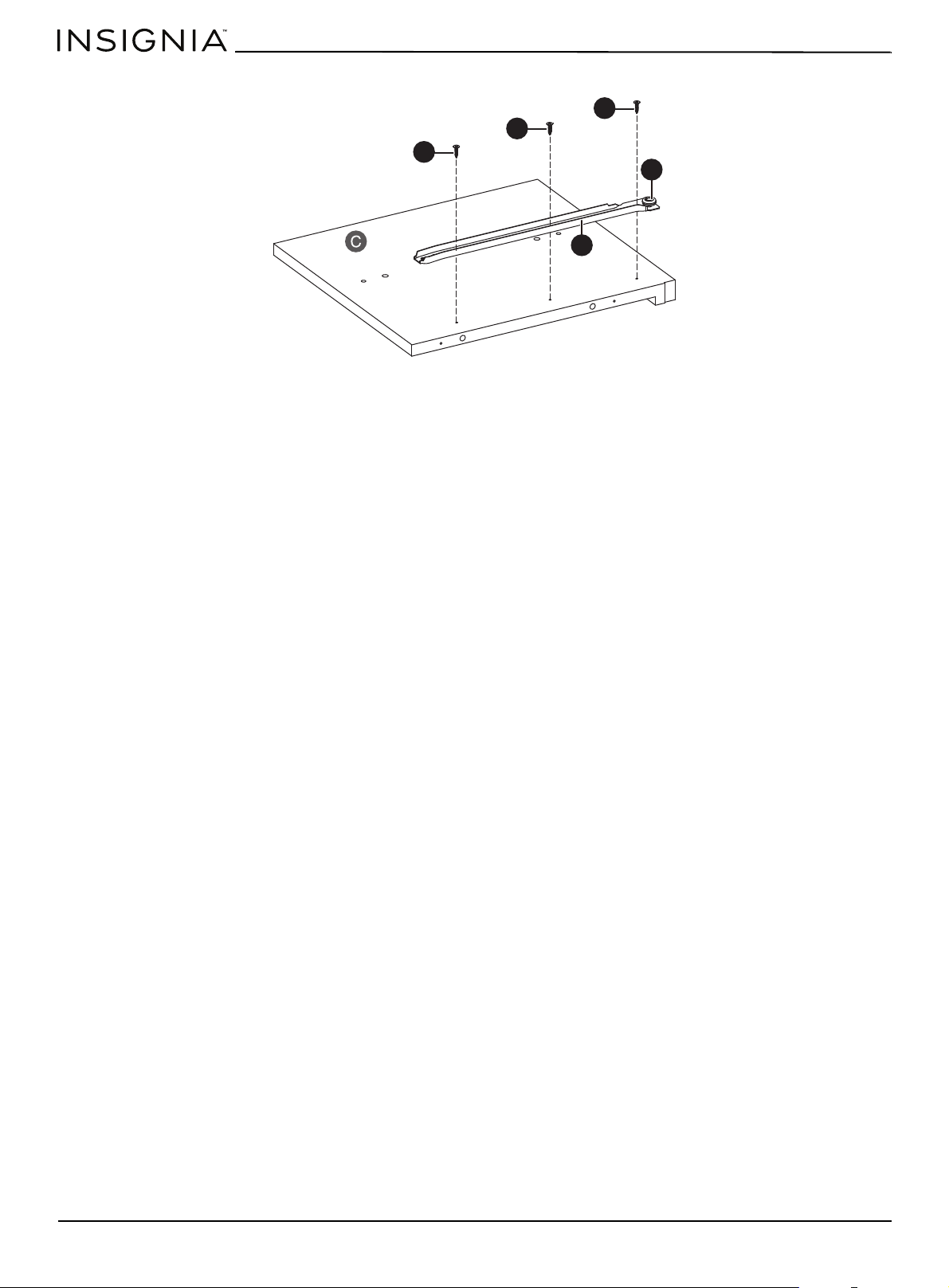
5 Align the CR part of the rail assembly (BB) to the inside of the right divider panel (C). Make sure that the wheel on the
assembly is at the back of the panel.
Phillips screwdriver
CR
DR
DL
CL
AA 3 × 12 mm
screw (6)
BB Left and right rail assembly (2)
B Left divider
panel (1)
C Right divider
panel (1)
Phillips screwdriver
AA AA AA
BB
AA
AA
AA
CL
www.insigniaproducts.com
8
58" TV Gaming Stand
6 Tighten the screws with a Phillips screwdriver.
CR
AA
AA
AA
BB
www.insigniaproducts.com
9
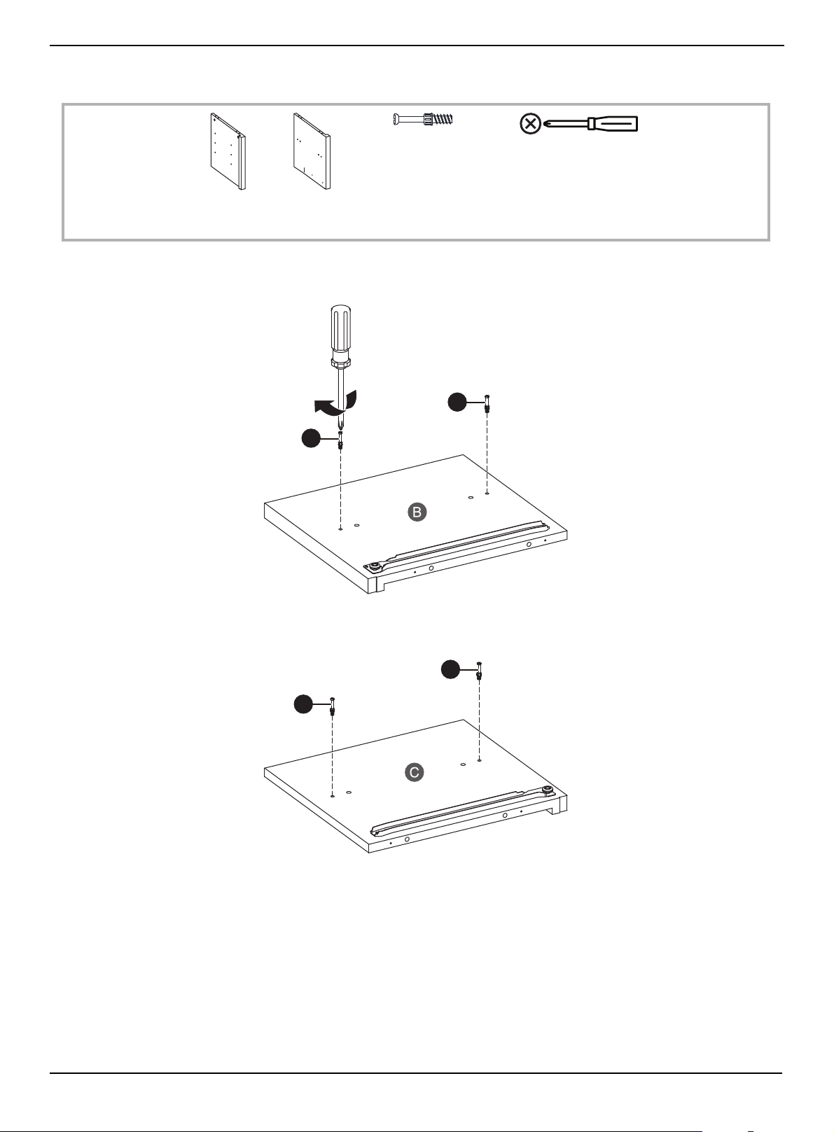
STEP 2:
You need:
1 Insert two cam screws (CC) into the holes on the left divider panel (B), then tighten the screws with a Phillips
screwdriver.
2 Insert two cam screws (CC) into the holes on the right divider panel (C), then tighten the screws with a Phillips
screwdriver.
CC Cam screw (4)
B Left divider
panel (1)
C Right divider
panel (1)
Phillips screwdriver
CC
CC
CC
CC
www.insigniaproducts.com
10
58" TV Gaming Stand
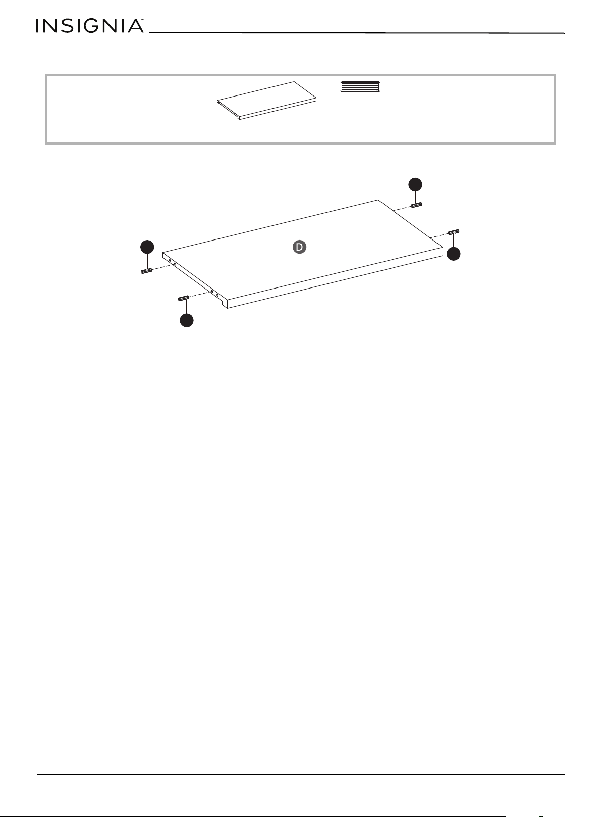
STEP 3:
You need:
•Insert four dowels (EE) into the short edges of the long lower shelf (D).
EE Dowel (4)
D Long lower shelf (1)
EE
EE
EE
EE
www.insigniaproducts.com
11
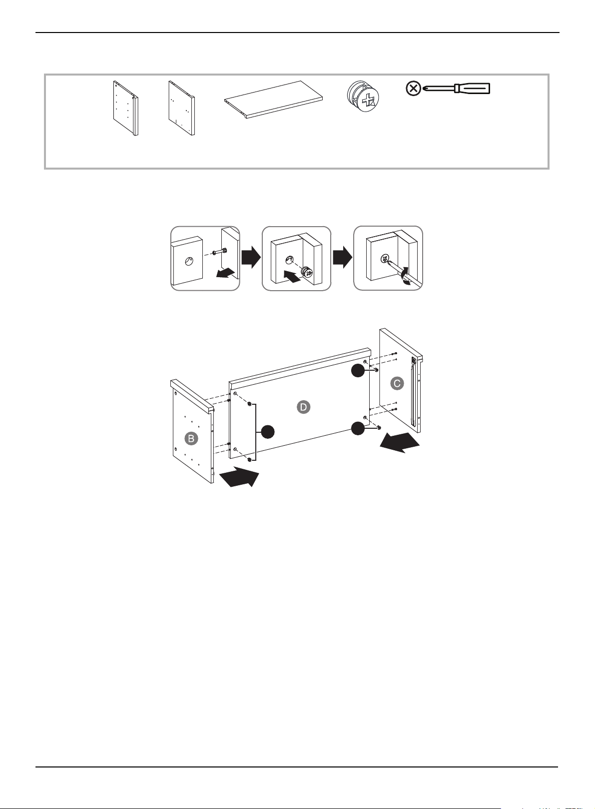
STEP 4:
You need:
Using cam locks
When you insert a cam lock, position the open end of the lock toward the cam screw, then insert the cam screw into the
cam lock opening.
1 Insert four cam locks (DD) into the long lower shelf (D).
2 Insert the cam screws on the divider panels (B and C) into the cam locks on the long lower shelf, then tighten the locks
with a Phillips screwdriver.
DD Small cam lock (4)
B Left divider
panel (1)
C Right divider
panel (1)
D Long lower shelf (1)
Phillips screwdriver
DD
DD
DD
www.insigniaproducts.com
12
58" TV Gaming Stand
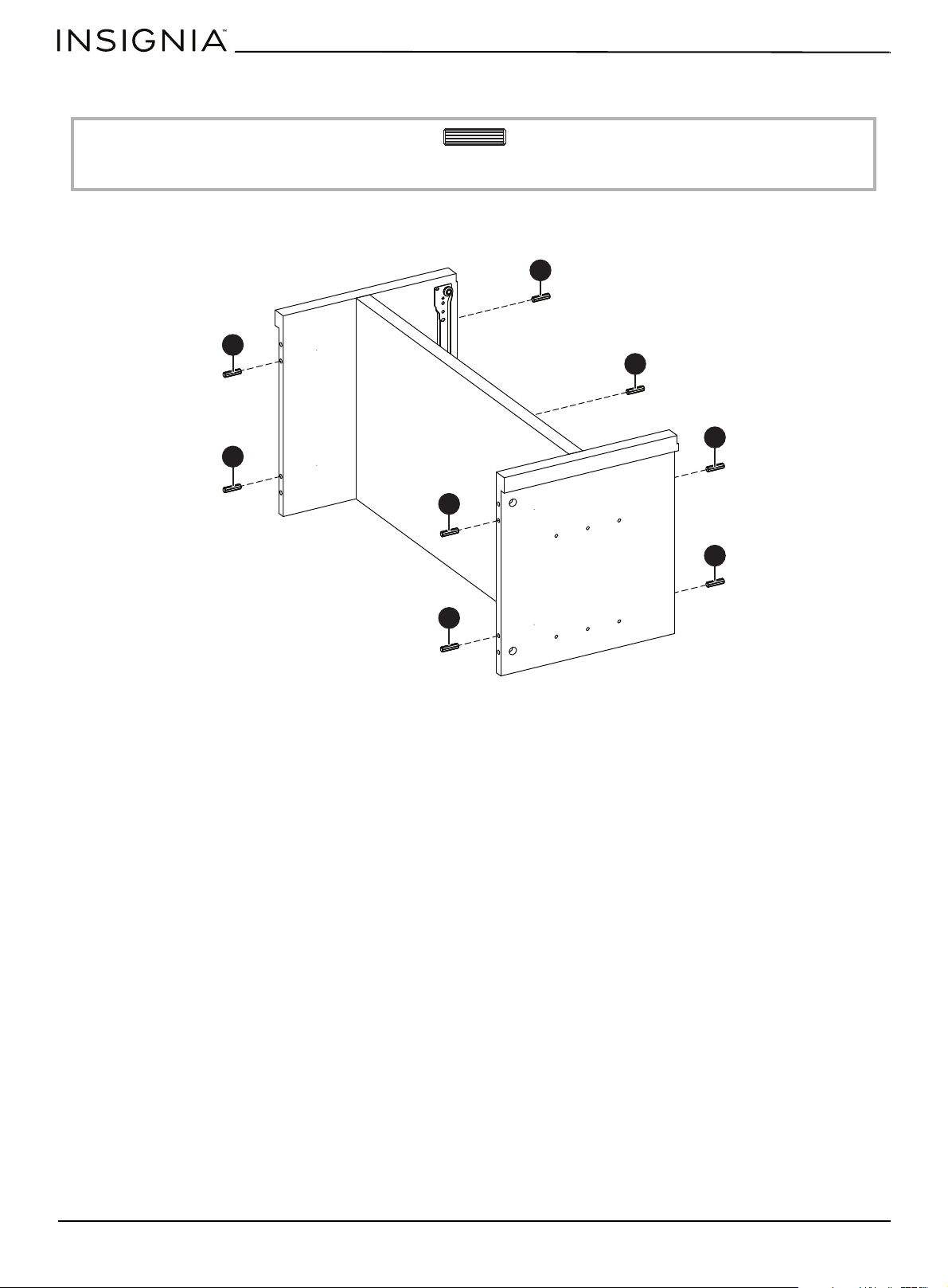
STEP 5:
You need:
•Insert eight dowels (EE) into the edges of the divider panels (B and C). Make sure that you use the inside hole of each
pair of holes.
EE Dowel (8)
EE
EE
EE
EE
EE
EE
EE
EE
www.insigniaproducts.com
13
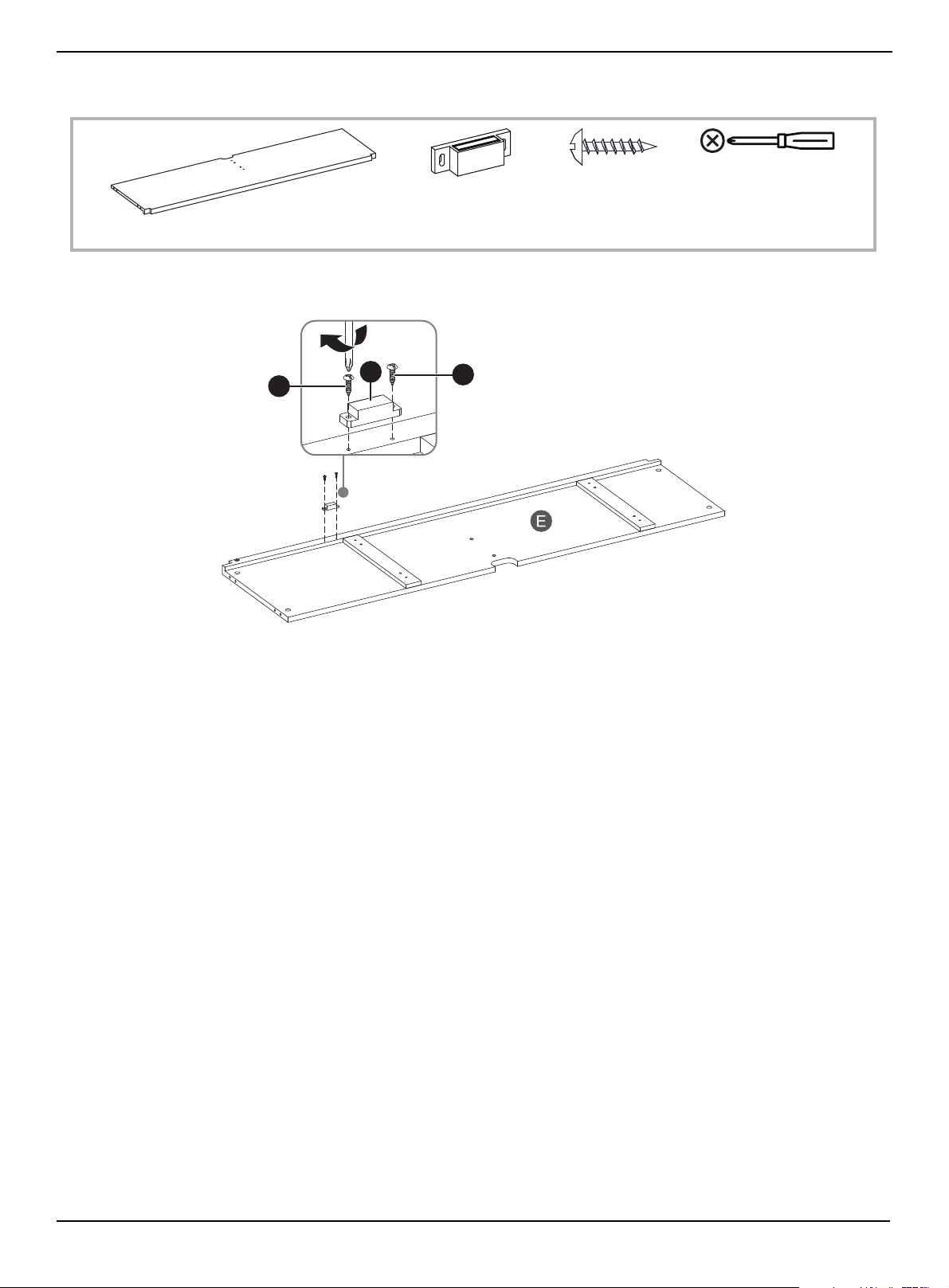
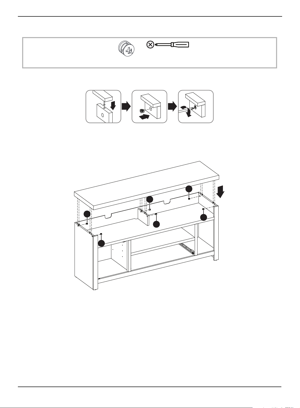
STEP 6:
You need:
• Align the magnetic door latch (GG) with the holes on the upper shelf (E), then secure the latch with two 3 × 15 mm
screws (FF) using a Phillips screwdriver. Make sure that you attach the latch to the side of the shelf that has cross bars.
FF 3 × 15 mm screw (2)
GG Magnetic
door latch (1)
E Upper shelf (1)
Phillips screwdriver
FF
FF
GG
www.insigniaproducts.com
14
58" TV Gaming Stand
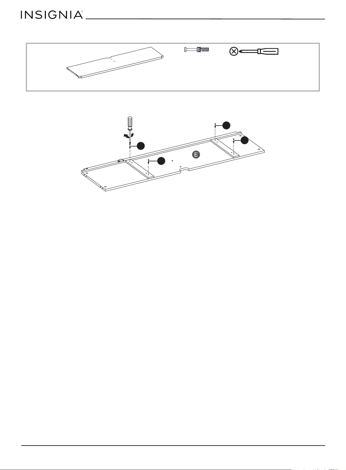
STEP 7:
You need:
•Insert four cam screws (CC) into the outer holes on the upper shelf (E), then tighten the screws using a Phillips
screwdriver.
CC cam screw (4)
E Upper shelf (1)
Phillips screwdriver
CC
CC
CC
CC
www.insigniaproducts.com
15
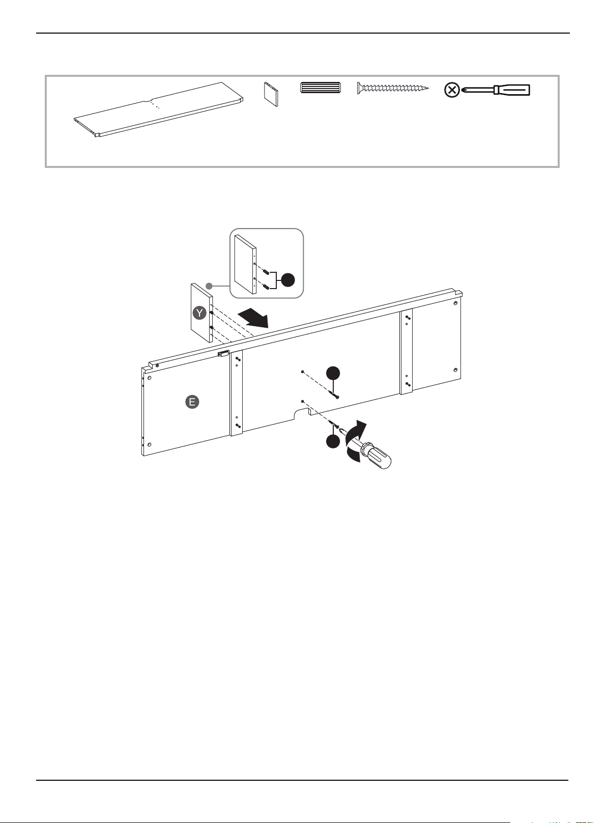
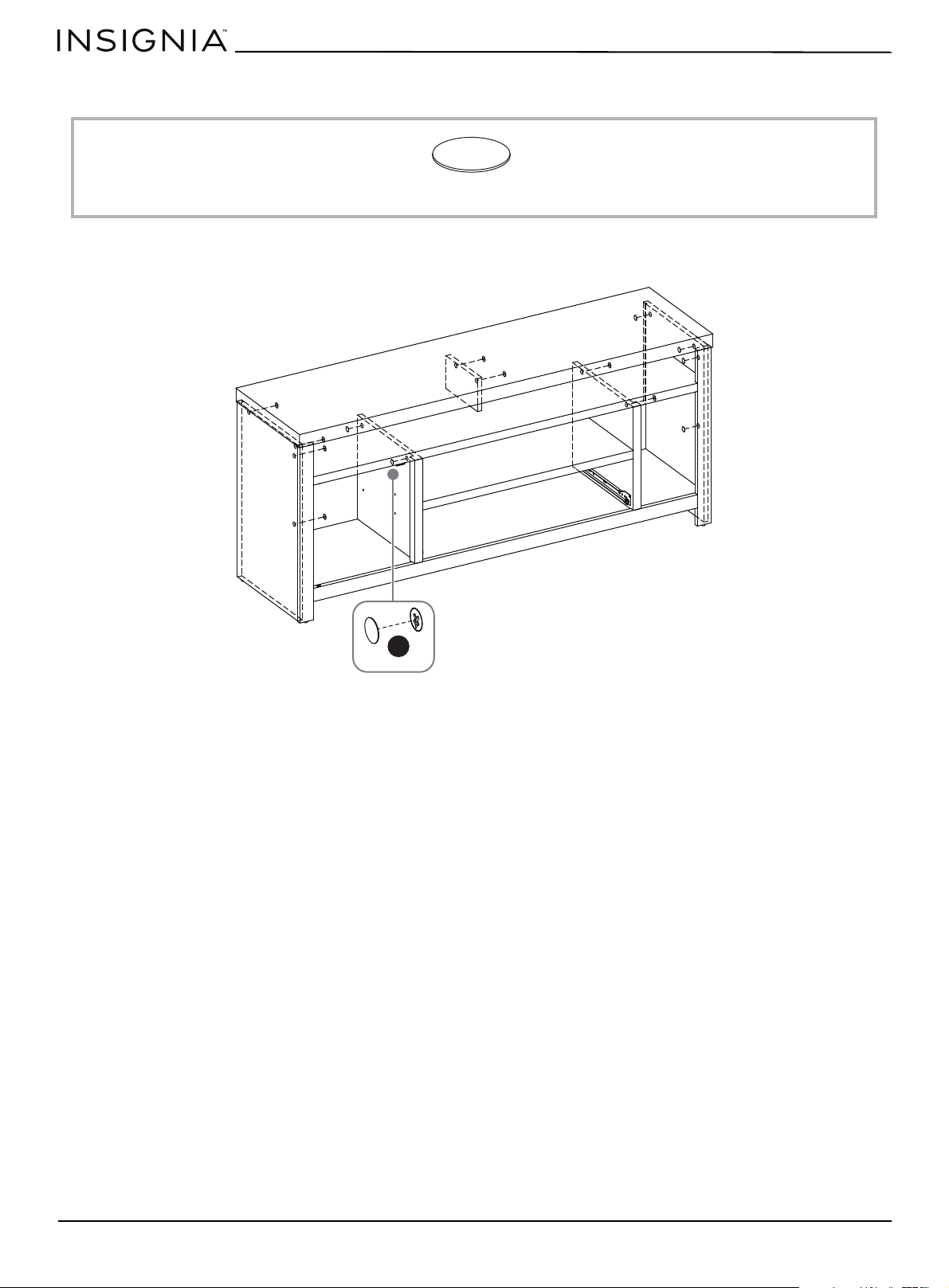
STEP 8:
You need:
1 Insert two dowels (EE) into the long edge of the small divider panel (Y).
2 Insert two 4 × 50 mm screws (HH) through the upper shelf (E) and into the small divider panel (Y), then tighten the
screws with a Phillips screwdriver.
E Upper shelf (1)
HH 4 × 50 mm screw
(2)
EE Dowel (2)
Y Small divider
panel (1)
Phillips screwdriver
HH
HH
EE
www.insigniaproducts.com
16
58" TV Gaming Stand
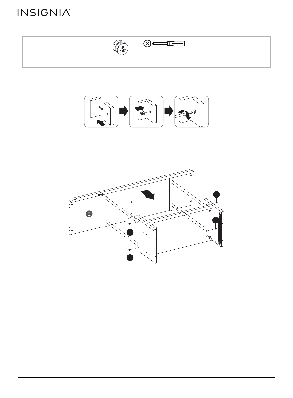
STEP 9:
You need:
Using cam locks
When you insert a cam lock, position the open end of the lock toward the cam screw, then insert the cam screw into the
cam lock opening.
1 Insert the dowels and cam screws on the upper shelf (E) into the dowel cam lock holes on the left and right divider
panels (B and C), then tighten the screws with a Phillips screwdriver.
2 Insert two cam locks (DD) into the left divider panel (B) and two into right divider panel (C) and make sure that the
openings on the cam locks cover the cam screws in the panels.
3 Tighten the cam locks with a Phillips screwdriver.
DD Cam lock (4)
Phillips screwdriver
DD
DD
DD
DD
www.insigniaproducts.com
17
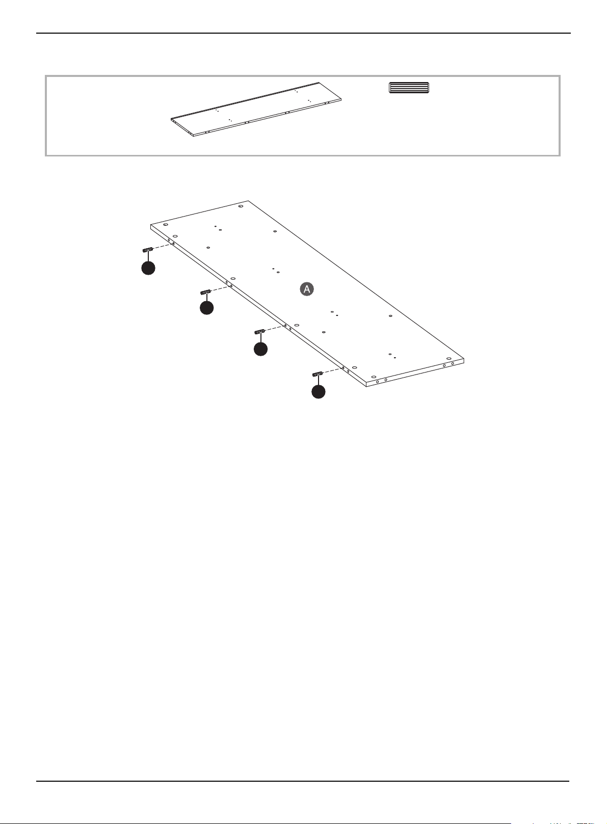
STEP 10:
You need:
•Insert four dowels (EE) into the edge of the base (A). Make sure that you use the holes that don’t have holes above
them.
EE Dowel (4)
A Base (1)
EE
EE
EE
EE

www.insigniaproducts.com
18
58" TV Gaming Stand
STEP 11:
You need:
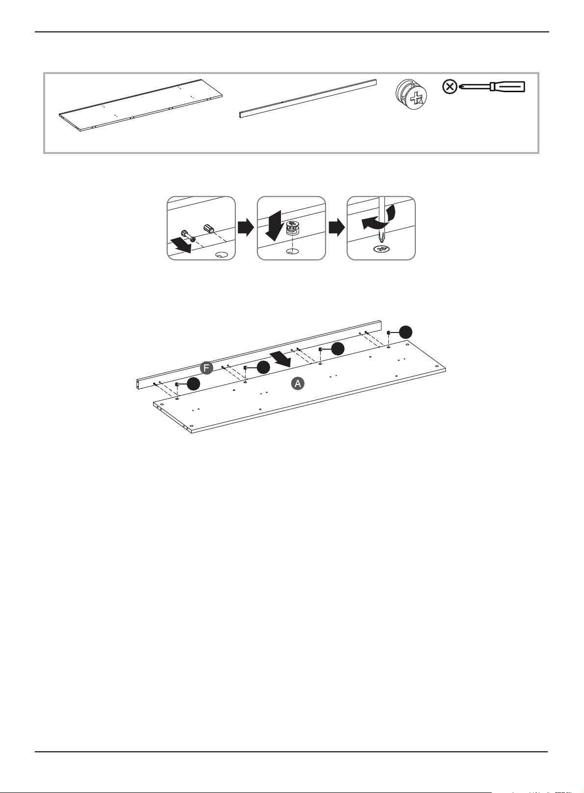
1 Insert four cam screws (CC) into the edge of the front edge (F). Make sure that you use the outer screw hole in each pair
of holes.
2 Tighten the screws with a Phillips screwdriver.
CC Cam screw (4)
F Front edge (1)
Phillips screwdriver
CC
CC
CC
CC
www.insigniaproducts.com
19
STEP 12:
You need:
When you insert a cam lock, position the open end of the lock toward the cam screw, then insert the cam screw into the
cam lock opening.
1 Insert four cam locks (DD) into the holes on the base (A).
2 Insert the cam screws and dowels on the front edge (F) into the cam locks and dowel holes on the base (A), then
tighten the cam locks with a Phillips screwdriver.
DD Cam lock (4)
A Base (1)
F Front edge (1)
Phillips screwdriver
DD
DD
DD
DD
www.insigniaproducts.com
20
58" TV Gaming Stand
STEP 13:
You need:
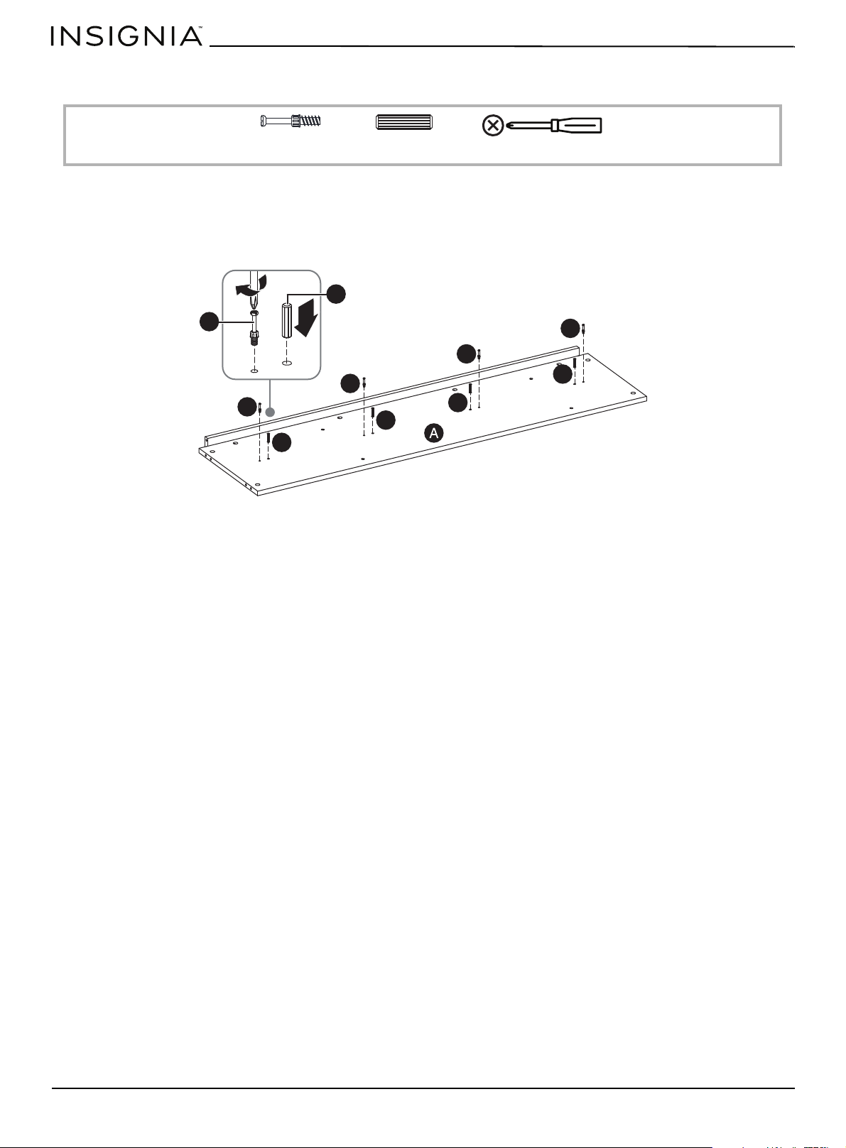
1 Insert four dowels (EE) into the middle holes on the base (A). Make sure that you use the inner hole on each pair of
holes.
2 Insert four cam screws (CC) into holes on the base. Make sure that you use the outer hole on each pair of holes.
3 Tighten the screws with a Phillips screwdriver.
CC Cam screw (4)
EE Dowel (4)
Phillips screwdriver
EE
EE
EE
EE
CC
CC
CC
CC
CC
EE
www.insigniaproducts.com
21
STEP 14:
You need:
When you insert a cam lock, position the open end of the lock toward the cam screw, then insert the cam screw into the
cam lock opening.
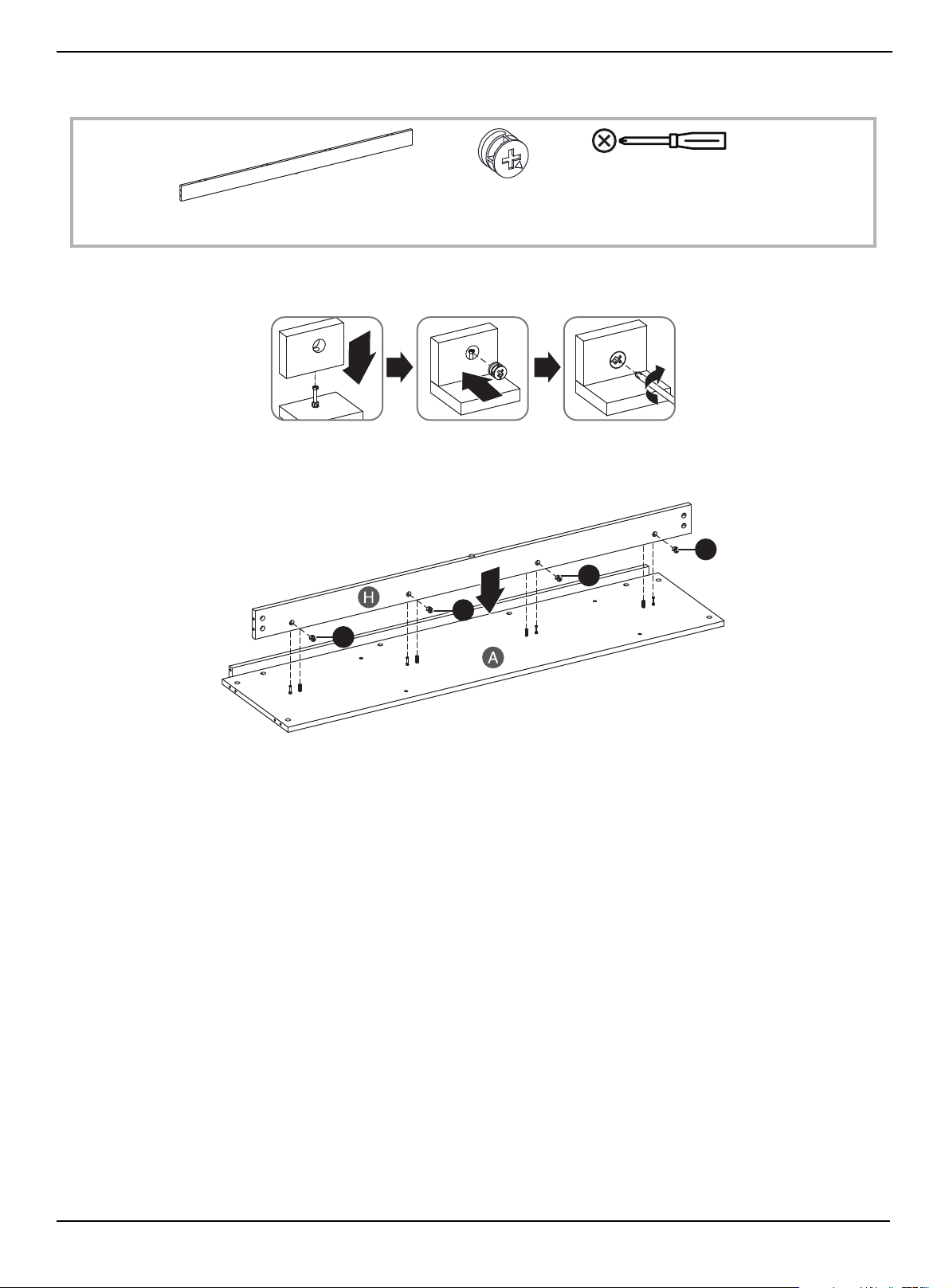
1 Insert four cam locks (DD) into lower support (H).
2 Insert the cam screws in the base (A) into the cam locks, then tighten the cam locks with a Phillips screwdriver.
DD Cam lock (4)
H Lower support (1)
Phillips screwdriver
DD
DD
DD
DD
www.insigniaproducts.com
22
58" TV Gaming Stand
STEP 15:
You need:
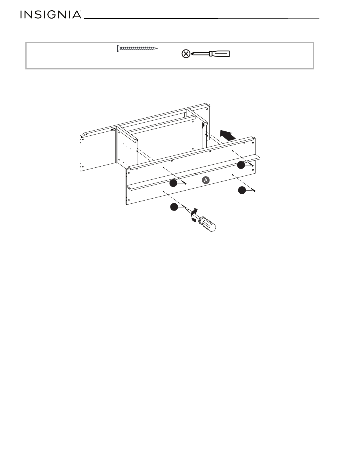
1 Insert four 4 × 50 mm screws (HH) through the base (A) and into the holes on the bottom edges of the left and right
divider panels.
2 Tighten the screws with a Phillips screwdriver.
HH 4 × 50 mm screw (4)
Phillips screwdriver
HH
HH
HH
HH
www.insigniaproducts.com
23
STEP 16:
You need:
1 Insert four dowels (EE) into the base (A).
2 Insert four dowels (EE) into the front edge (F).
3 Insert four dowels (EE) into the left and right divider panels (A and B).
EE Dowel (12)
EE
EE
EE
EE
EE
EE
EE
EE
EE
www.insigniaproducts.com
24
58" TV Gaming Stand
STEP 17:
You need:
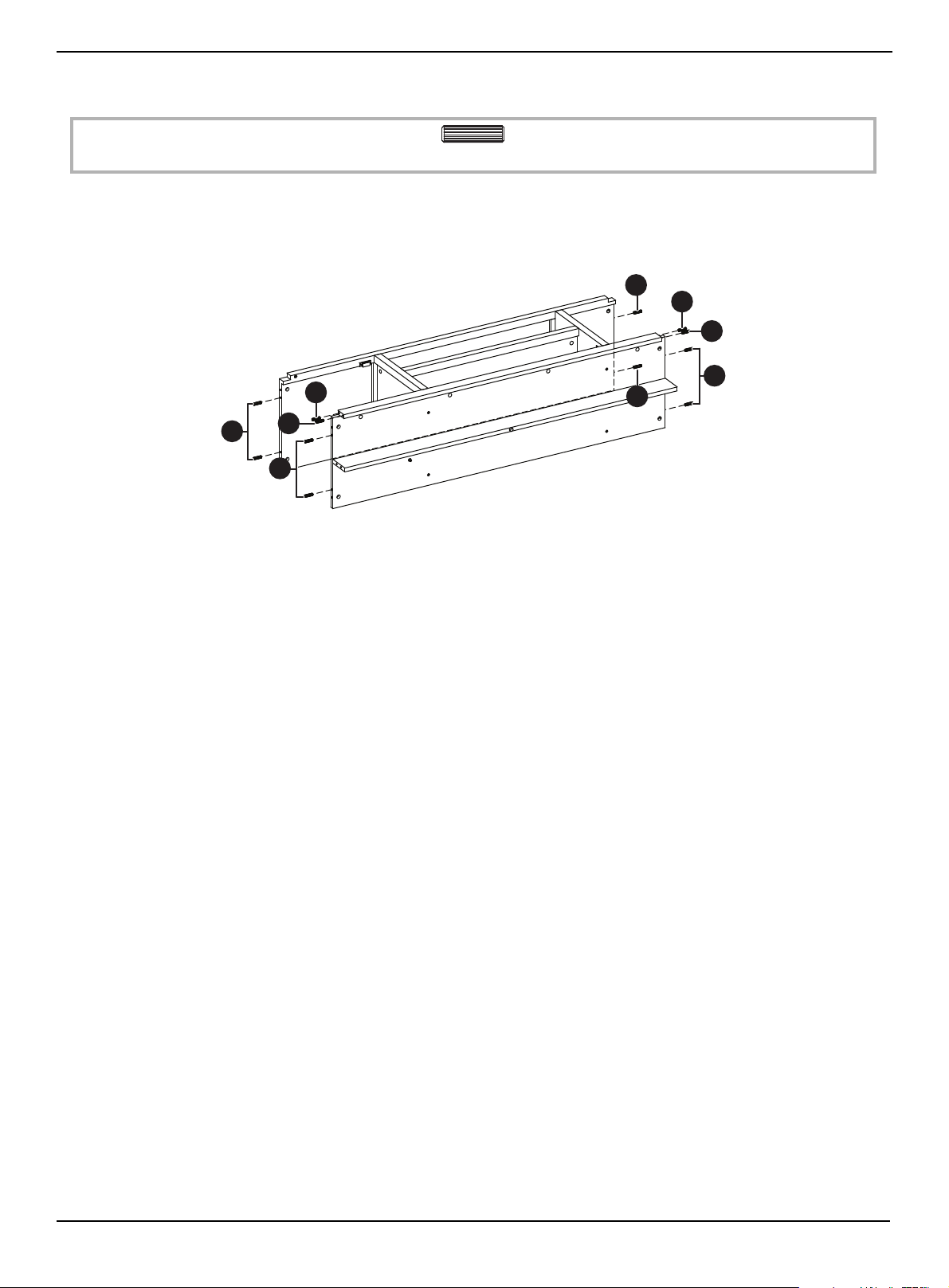
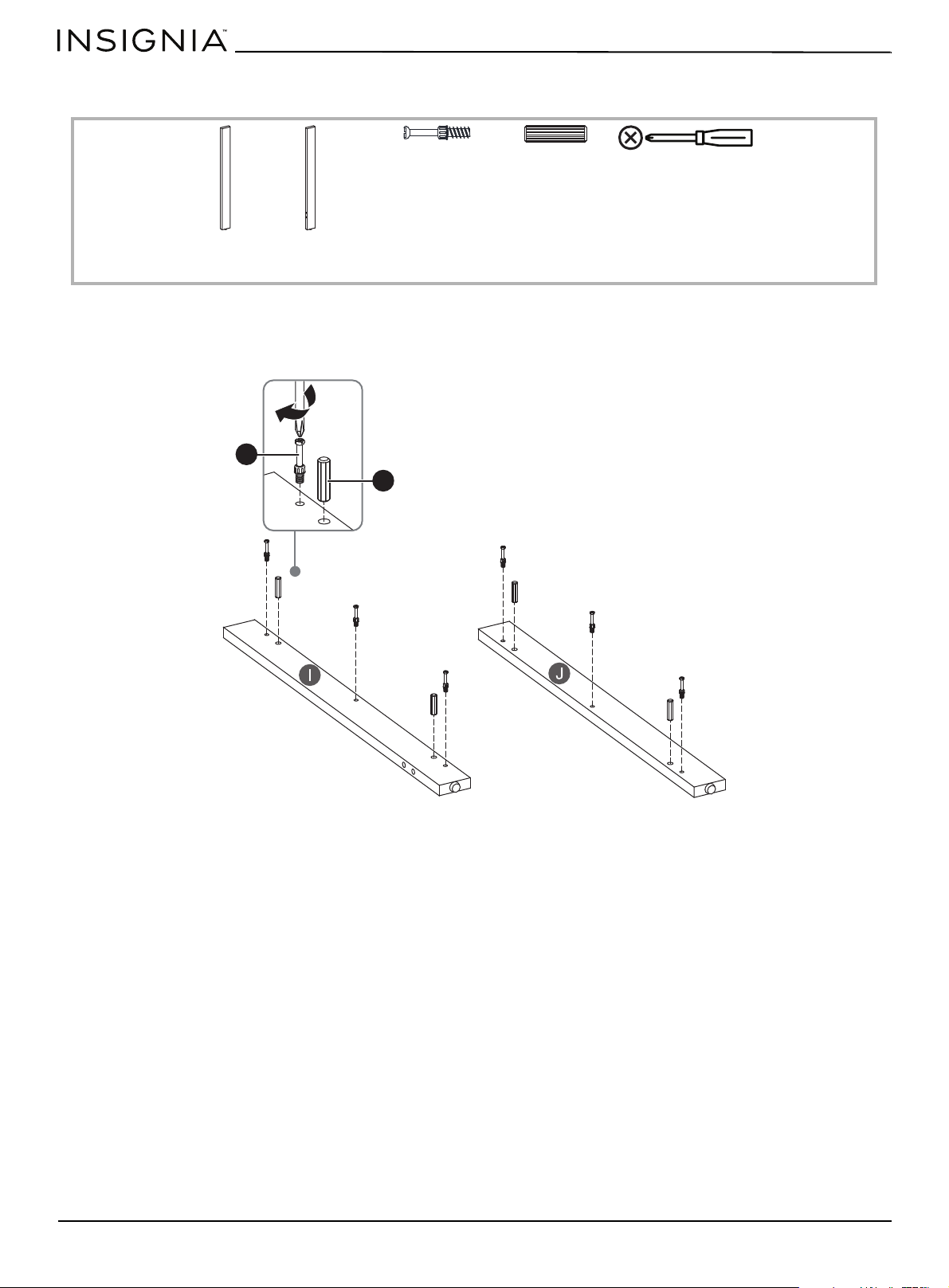
1 Insert three cam screws (CC) and two dowels (EE) into the left side support (I) and three cam screws and two dowels
into the right side support (J).
2 Tighten the screws with a Phillips screwdriver.
CC Cam screw (6)
EE Dowel (4)
I Left side
support (1)
J Right side
support (1)
Phillips screwdriver
EE
CC
www.insigniaproducts.com
25
STEP 18:
You need:
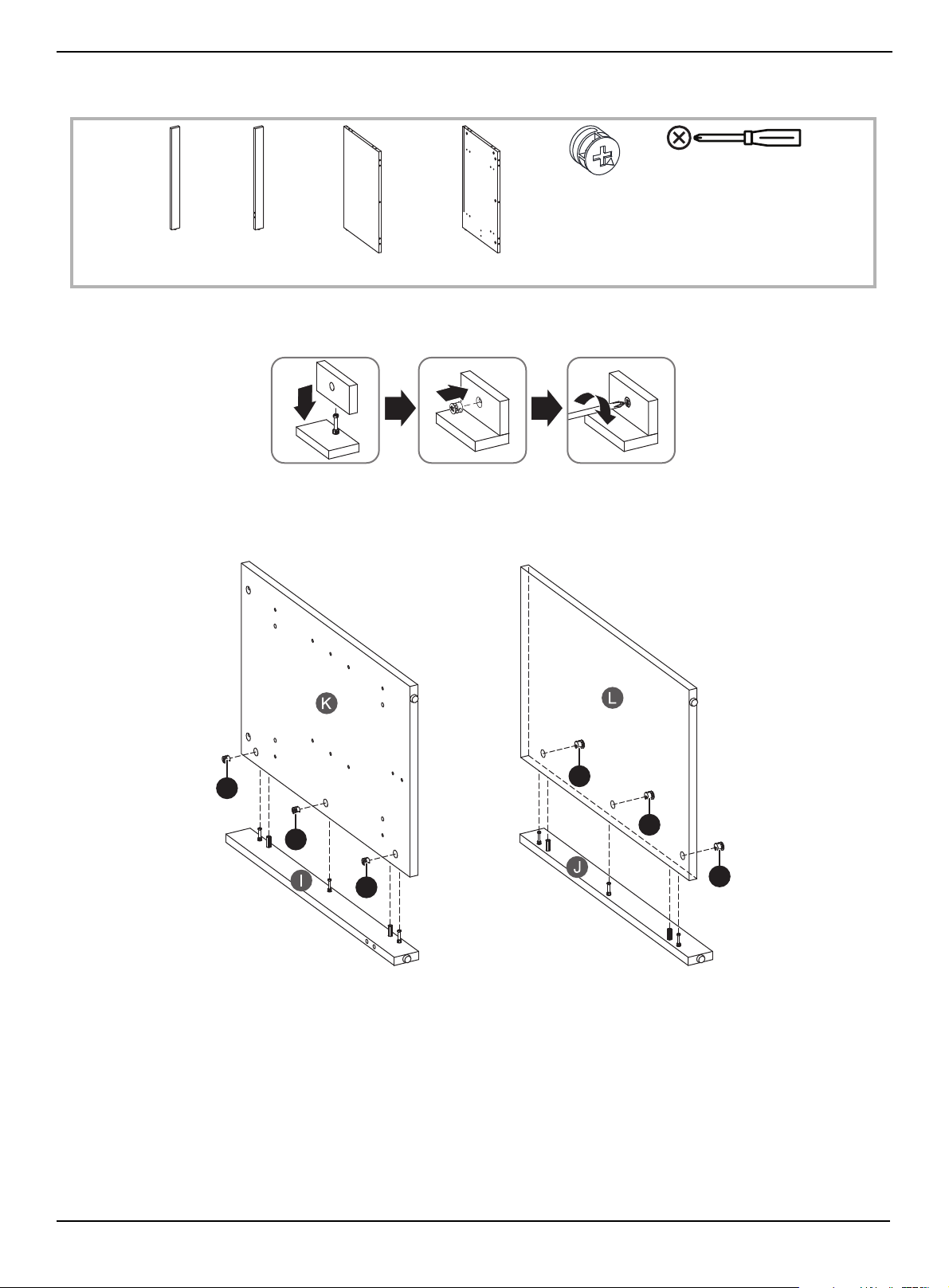
When you insert a cam lock, position the open end of the lock toward the cam screw, then insert the cam screw into the
cam lock opening.
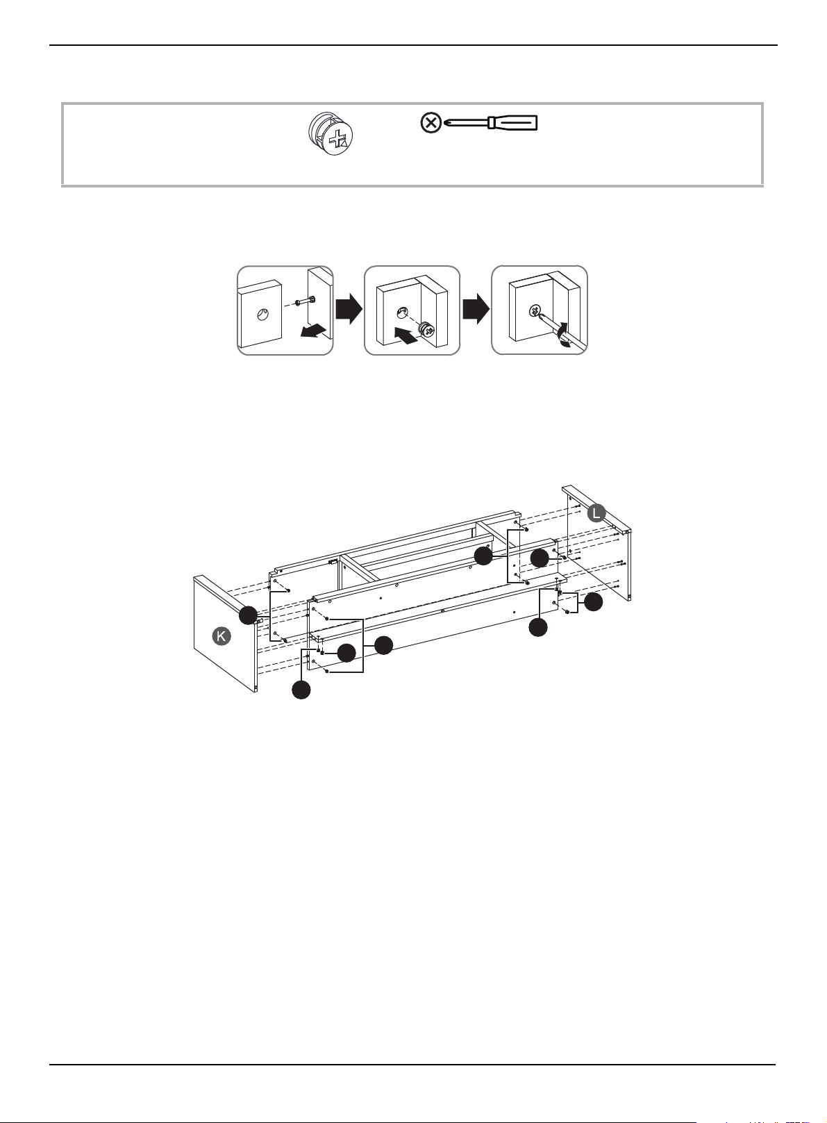
1 Insert three cam locks (DD) into the left side (K) and three cam locks into the right side (L).
2 Insert the cam screws on the left support (I) and right support (J) into the cam locks on the left and right sides, then
tighten the screws with a Phillips screwdriver.
DD Cam lock (6)
K left side (1) L Right side (1)
I Left side
support (1)
J Right side
support (1)
Phillips screwdriver
DD
DD
DD
DD
DD
DD
www.insigniaproducts.com
26
58" TV Gaming Stand
STEP 19:
You need:
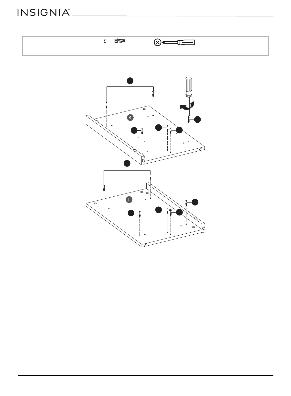
• Insert six cam screws (CC) into the left side (K) and six cam screws into the right side (L), then tighten the screws with a
Phillips screwdriver.
CC Cam screw (12)
Phillips screwdriver
CC
CC
CC
CC
CC
CC
CC
CC
CC
CC
www.insigniaproducts.com
27
STEP 20:
You need:
Using cam locks
When you insert a cam lock, position the open end of the lock toward the cam screw, then insert the cam screw into the
cam lock opening.
r
1 Insert one cam lock (DD) into each corner of the bottom of the upper shelf (E).
2 Insert one cam lock into each corner of the bottom of the base (A).
3 Insert two cam locks into the bottom of the left and right sides of the lower shelf (H).
4 Insert the six cam screws on the right side (K) into the cam locks, then tighten the cam locks with a Phillips screwdriver.
5 Insert the six cam screws on the right side (L) into the cam locks, then tighten the cam locks with a Phillips screwdriver.
DD Cam lock (12)
Phillips screwdriver
DD
DD
DD
DD
DD
DD
DD
DD
www.insigniaproducts.com
28
58" TV Gaming Stand
STEP 21:
You need:
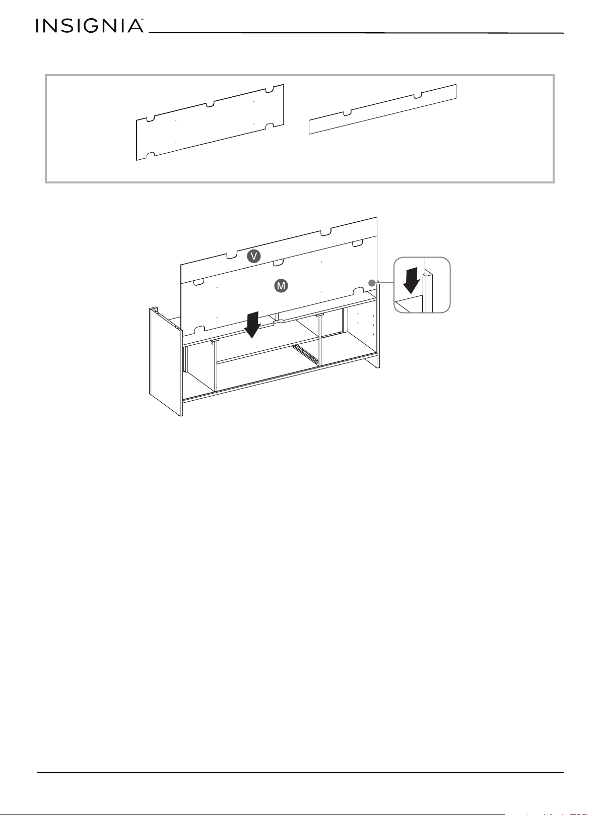
• Slide the lower back panel (M) into the grooves on the left and right sides (K and L) then slide the upper back panel (V).
M Lower back panel (1)
V Upper back panel (1)
www.insigniaproducts.com
29
STEP 22:
You need:
•Insert two dowels (EE) into the top edges of the left side (K), the right side (K), and the small divider (Y). Make sure that
you use the inside hole in each pair of holes.
EE Dowel (6)
EE
EE
EE
EE
EE
EE
www.insigniaproducts.com
30
58" TV Gaming Stand
STEP 23:
You need:
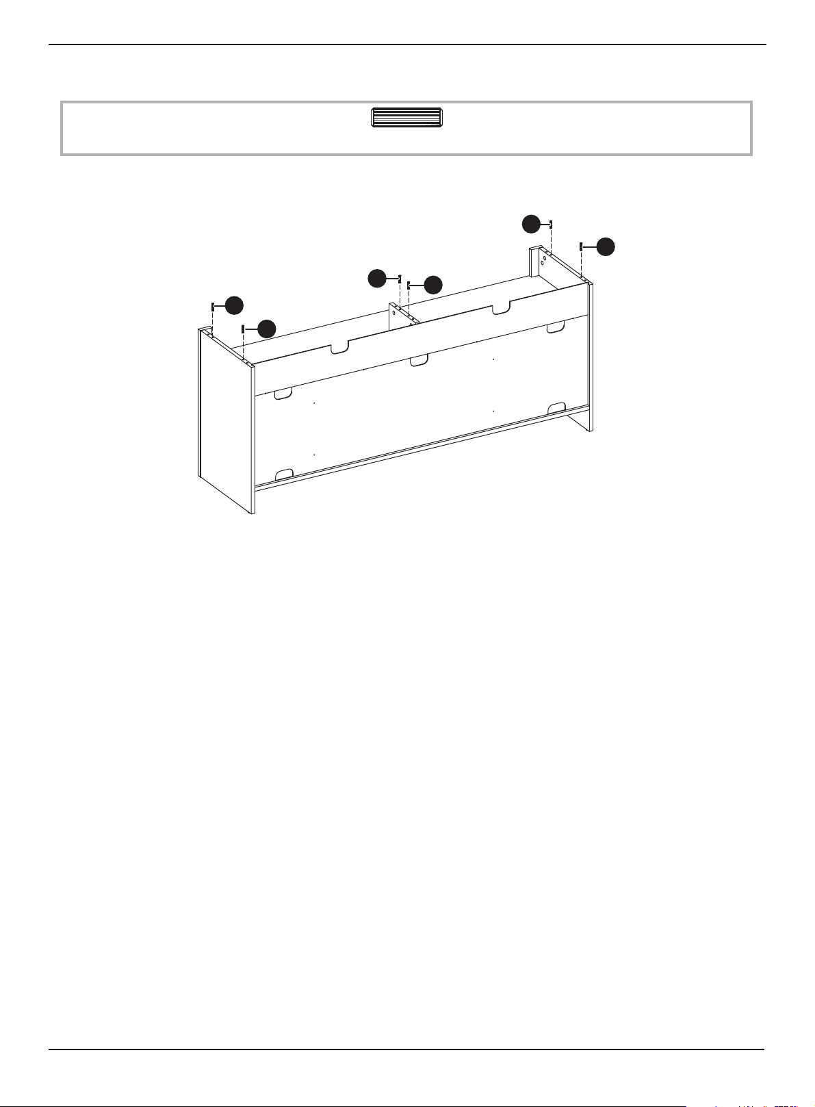
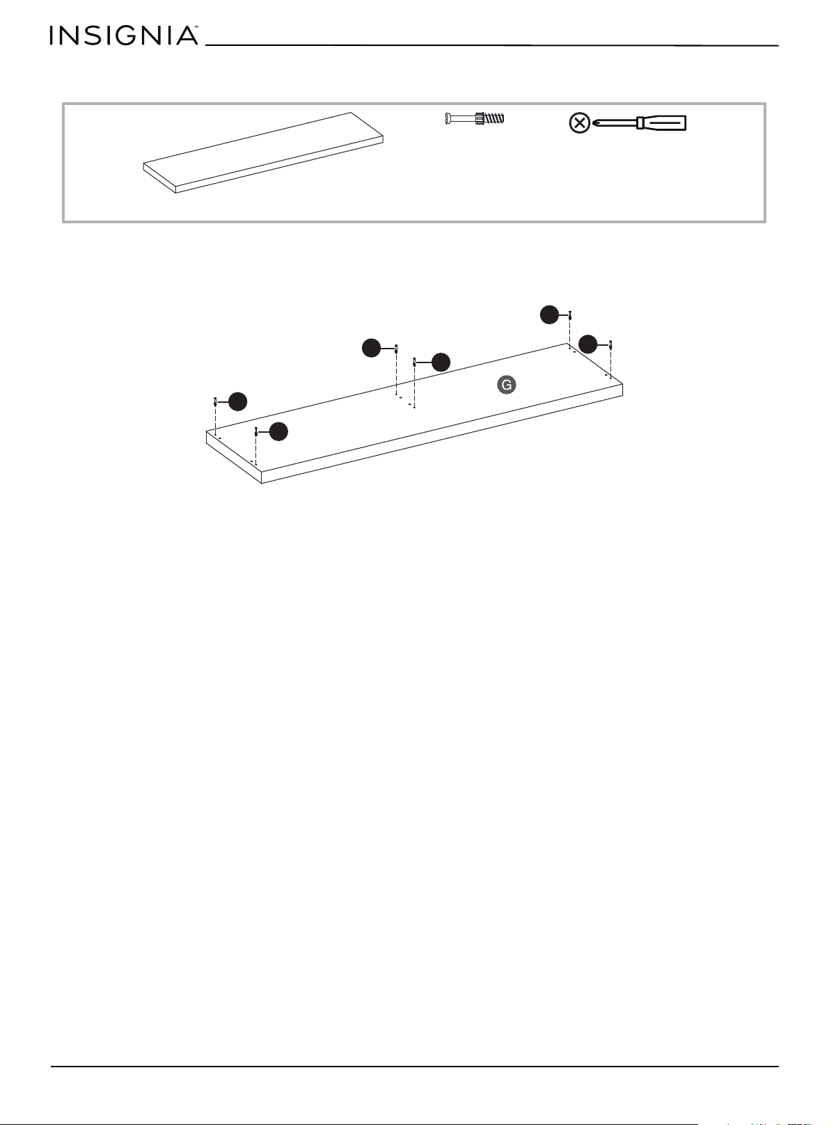
1 Insert one cam screw (CC) into each corner and the middle of the top (G). Make sure that you use the outside hole of
each pair of holes.
2 Tighten all screws with a Phillips screwdriver.
CC Cam screw (6)
Phillips screwdriver
G Top (1)
CC
CC
CC
CC
CC
CC
www.insigniaproducts.com
31
STEP 24:
You need:
When you insert a cam lock, position the open end of the lock toward the cam screw, then insert the cam screw into the
cam lock opening.
1 Insert two cam locks (DD) into the inside top edges of the left side (K), the right side (K), and the left top side of the
small divider (Y).
2 Lay the top (G) onto the left and right sides. Make sure that the cam screws fit into the cam locks,
3 Tighten all cam locks with a Phillips screwdriver.
DD Cam lock (6)
Phillips screwdriver
DD
DD
DD
DD
DD
DD
www.insigniaproducts.com
32
58" TV Gaming Stand
STEP 25:
You need:
• Snap cam lock covers (W) over the exposed cam locks on the left and right sides, the small divider (panel), and the left
and right divider panels.
VV Cam lock cover (14)
VV

www.insigniaproducts.com
33
STEP 26:
You need:
• Insert twelve back brackets (RR) into the edges of the back panels, then secure each bracket with a 3.5 × 16 mm
screw (SS).
SS 3.5 × 16 mm screw (12)
RR Back support bracket (12)
Phillips screwdriver
SS
RR
www.insigniaproducts.com
34
58" TV Gaming Stand
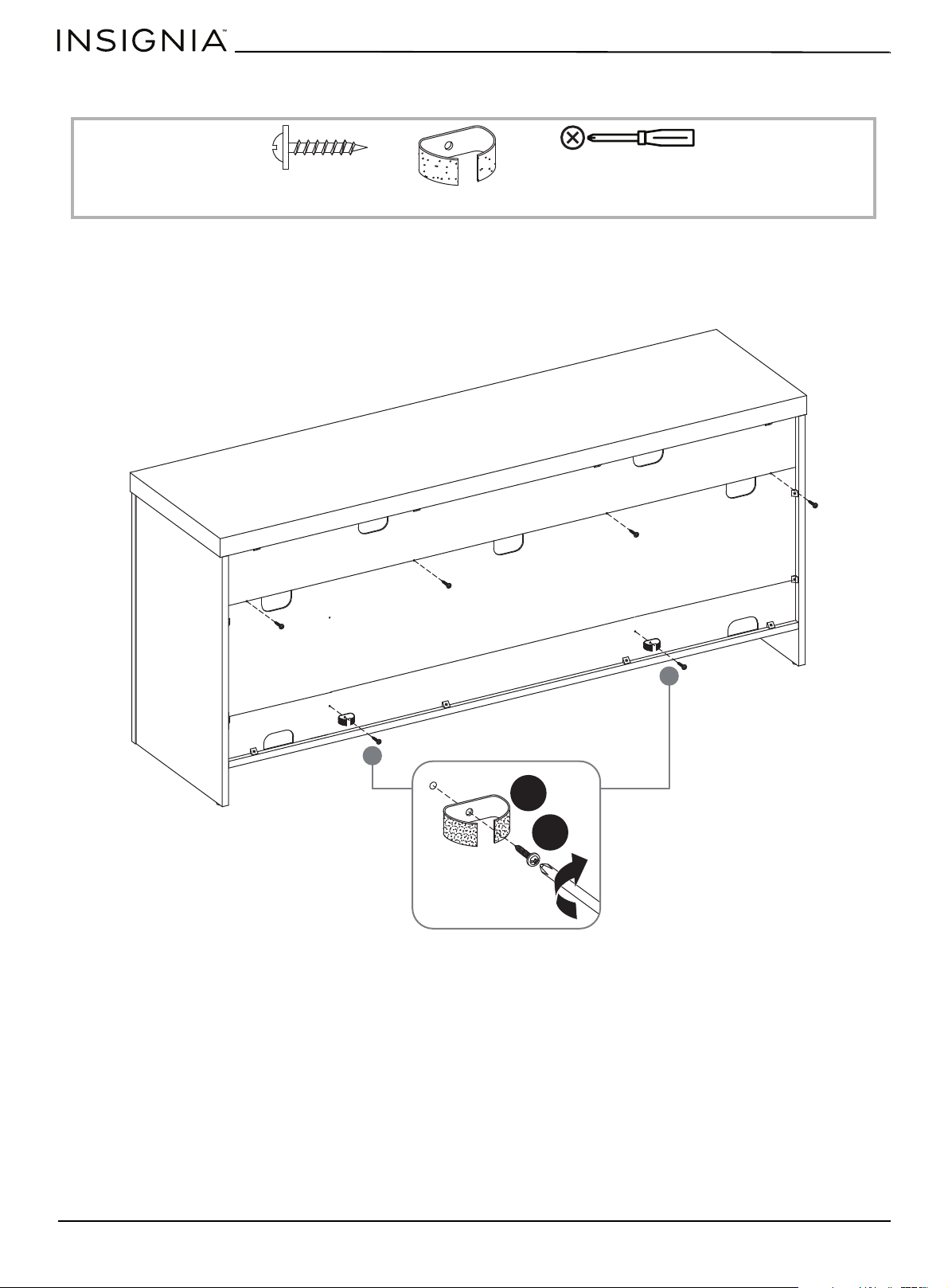
STEP 27:
You need:
1 Insert six 3 × 16 mm screw (II) along the outer edges of the lower back (M), then tighten the screws with a Phillips
screwdriver.
2 Align two cable wraps (TT) with the holes in the middle of the lower back, then secure each wrap with a 3 × 16 mm
screw (II) using a Phillips screwdriver.
TT Cable wrap (2)
II 3 × 16 mm screw (6)
Phillips screwdriver
TT
II
www.insigniaproducts.com
35
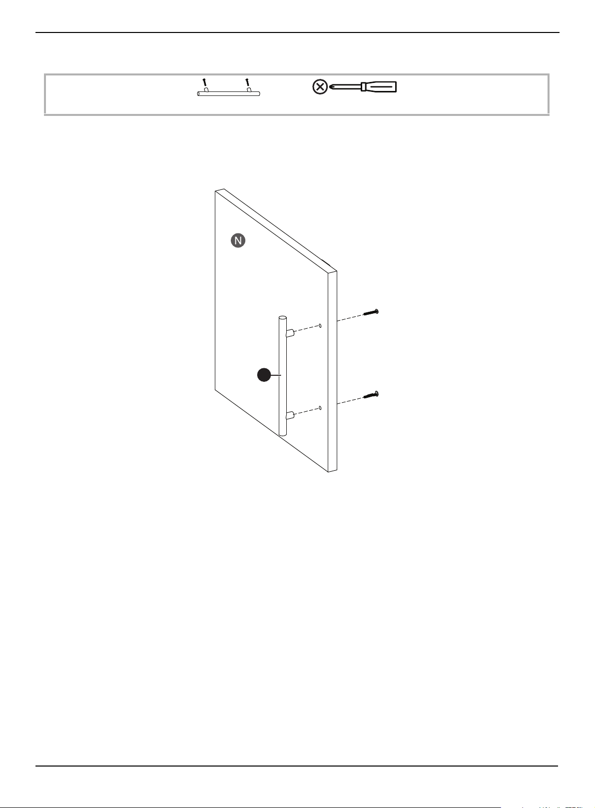
STEP 28:
You need:
1 Remove the screws from the handle (JJ).
2 Align the handle with the holes on the outside of the door (N), then insert the screws through the inside of the door
and into the handle.
3 Tighten the screws with a Phillips screwdriver.
JJ Handle (1)
Phillips screwdriver
JJ
www.insigniaproducts.com
36
58" TV Gaming Stand
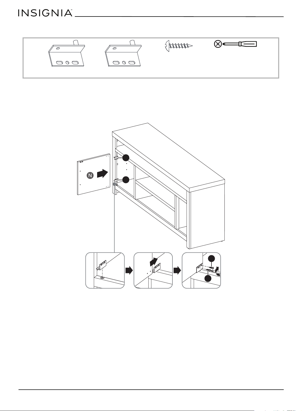
STEP 29:
You need:
1 Insert the lower hinge pin (KK) into the pin hole on the left bottom of cabinet.
2 Insert the upper hinge pin (LL) into the pin hole on the left top of cabinet.
3 With the handle facing out, slide the door (N) onto the hinge pins that the screw holes on the door align with the holes
in the hinge pins.
4 Secure the door to each hinge pin with two 3 × 15 mm screws (FF) using a Phillips screwdriver.
KK Lower hinge pin (1)
LL Upper hinge pin (1)
FF 3 × 15 mm screw (4)
Phillips screwdriver
FF
FF
LL
KK
www.insigniaproducts.com
37
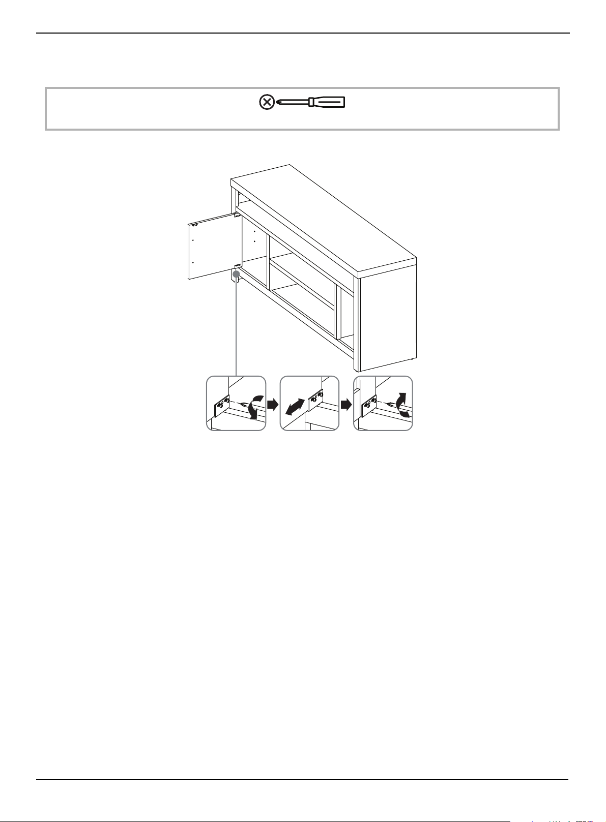
STEP 30:
After the door is installed, you might need to adjust the door so that it fits snuggly into the cabinet.
You need:
• Loosen the hinge pin screws, slightly slide the door forward or back, then tighten the screws.
Phillips screwdriver
www.insigniaproducts.com
38
58" TV Gaming Stand
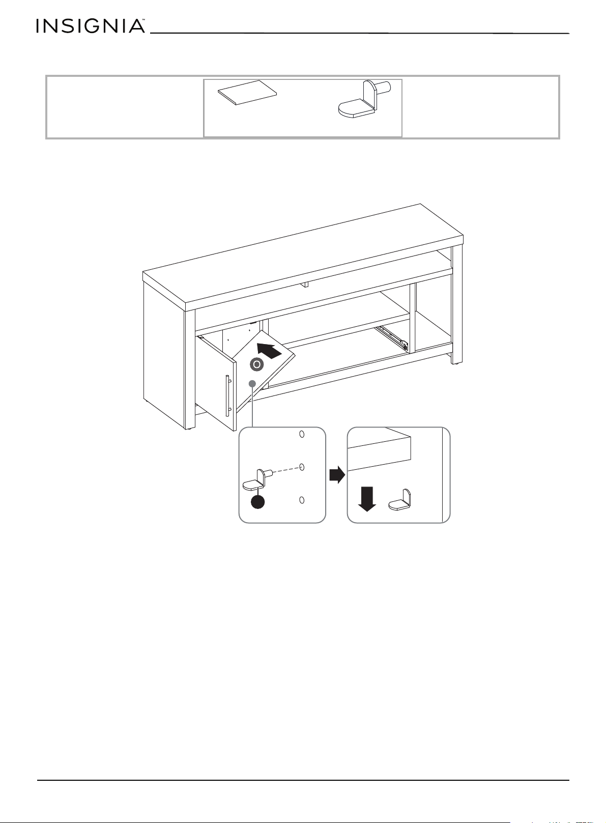
STEP 31:
You need:
1 Insert the four shelf supports (MM) inside the cabinet. Make sure that all the supports are on the same level.
2 Tilt the short upper shelf (O), then slide the shelf above the shelf supports and into the cabinet.
3 Lower the shelf onto the supports.
MM shelf support (4)
O Short upper shelf (1)
MM
www.insigniaproducts.com
39
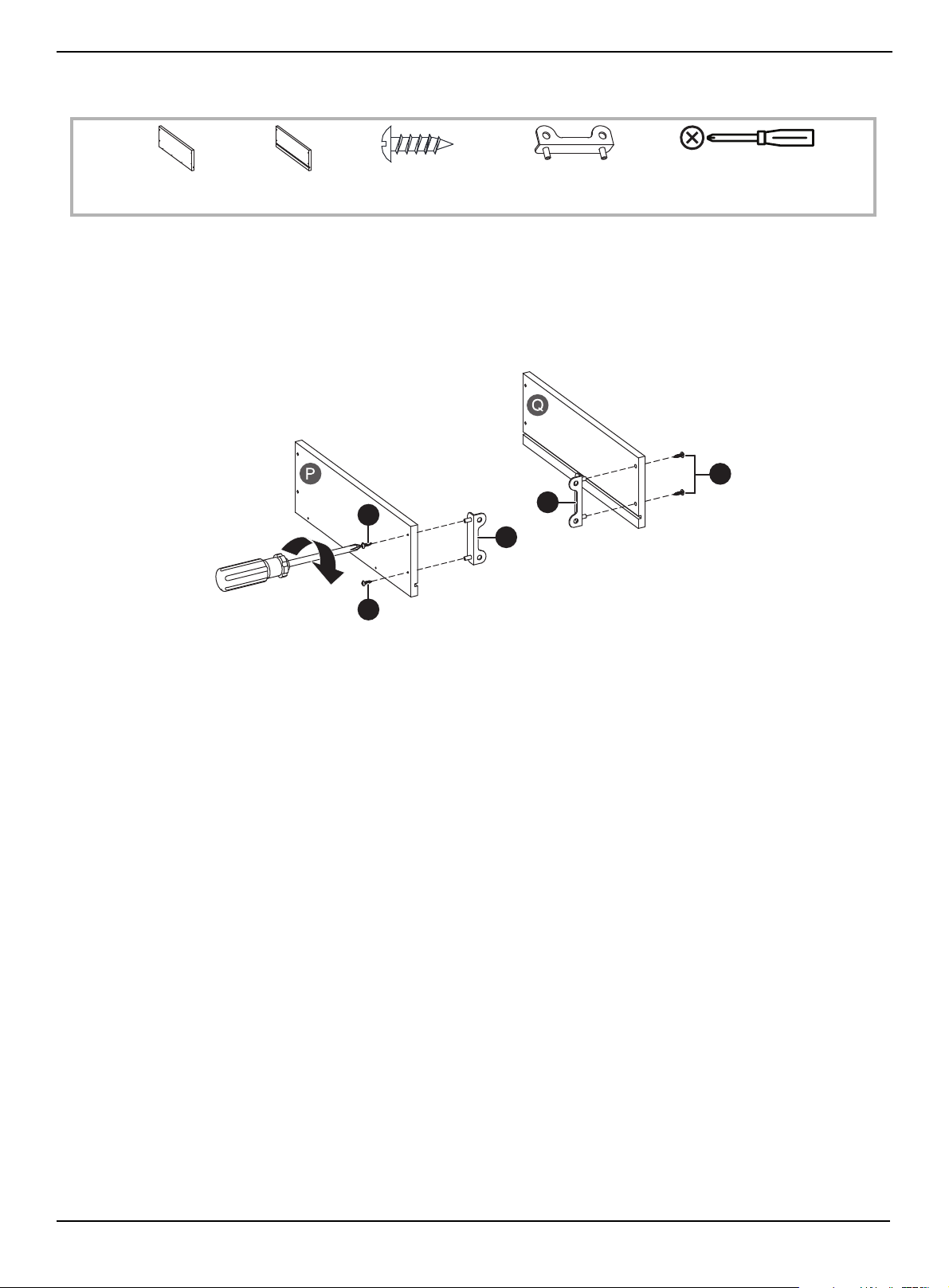
STEP 32:
You need:
1 Align a drawer support (OO) with the holes on the inside of the left drawer side (P), then insert two 3.5 × 12 mm screws
(NN) through the outside of the drawer and into the support.
2 Tighten the screws with a Phillips screwdriver.
3 Align a drawer support (OO) with the holes on the inside of the right drawer side (Q), then insert two 3.5 × 12 mm
screws (NN) through the outside of the drawer and into the support.
4 Tighten the screws with a Phillips screwdriver.
NN 3.5 × 12 mm
screw (4)
OO Drawer support (2)
Phillips screwdriver
P Left drawer
side (1)
Q Right drawer
side (1)
OO
NN
NN
OO
OO
www.insigniaproducts.com
40
58" TV Gaming Stand
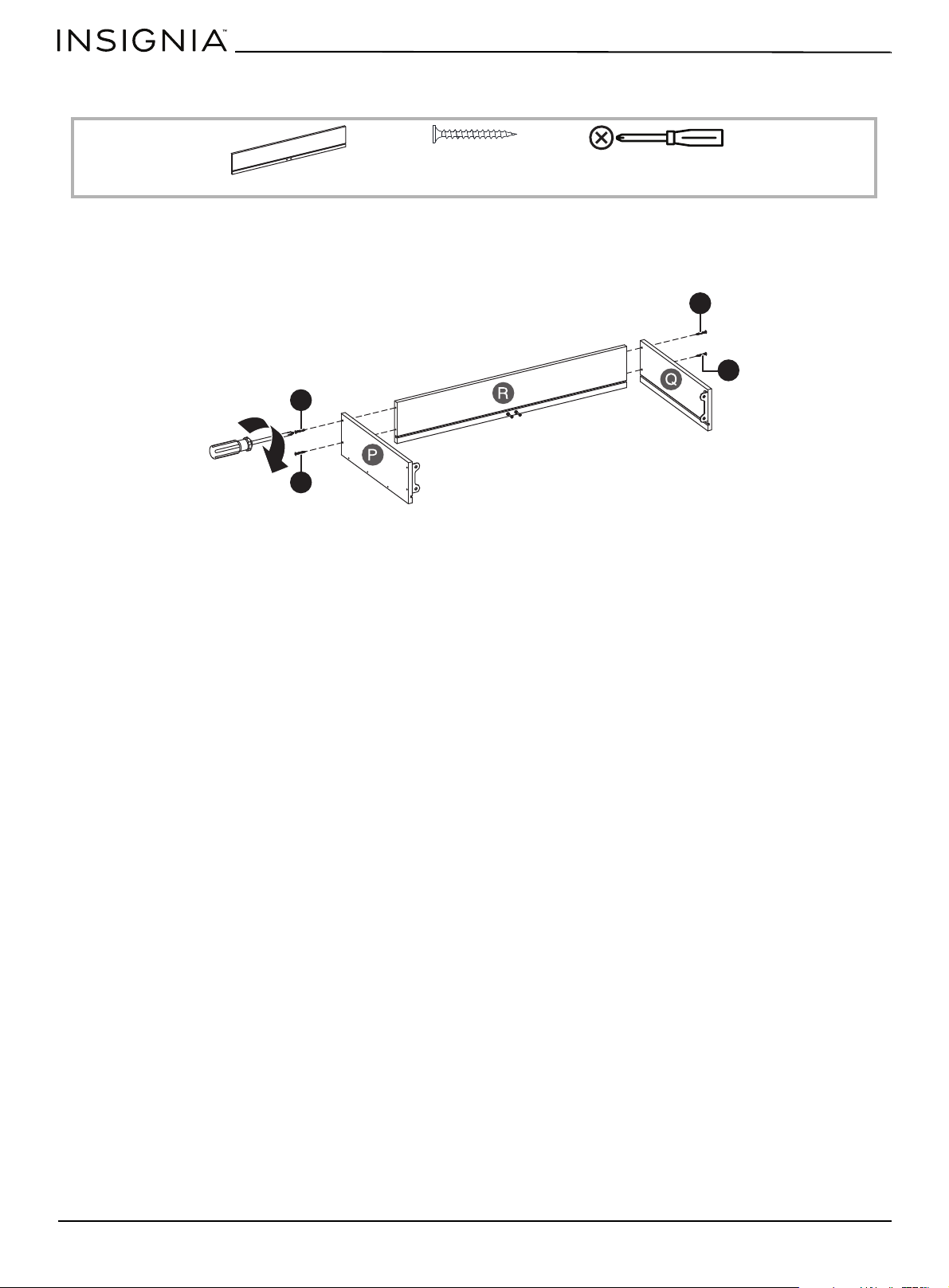
STEP 33:
You need:
1 With the grooves in the drawer back (R) and the left and right drawer sides (P and Q) facing inward, insert two
4×38mm screws (PP) through the left and right drawer sides and into the drawer back.
2 Tighten the screws with a Phillips screwdriver.
Phillips screwdriver
R Drawer back (1)
PP 4 × 38 mm screw
(4)
PP
PP
PP
PP
www.insigniaproducts.com
41
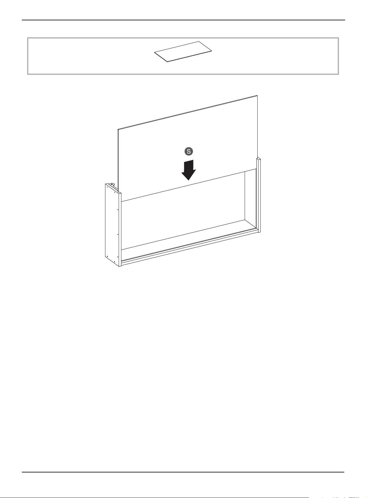
STEP 34:
• With the drawer back facing down, slide the drawer bottom (S) into the grooves on the drawer sides and back.
S Drawer bottom (1)
www.insigniaproducts.com
42
58" TV Gaming Stand
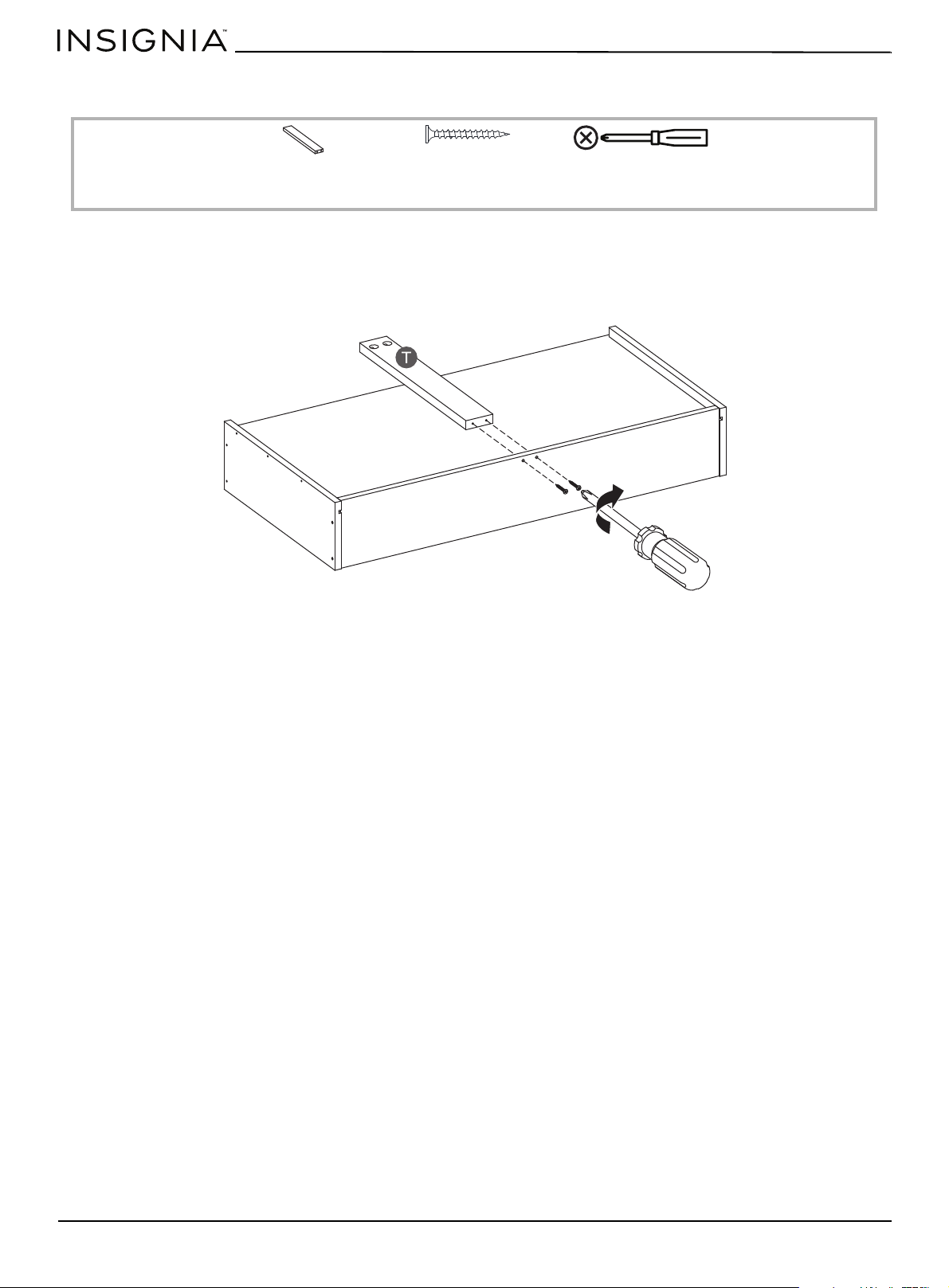
STEP 35:
You need:
1 Insert two 4 × 38 mm screws (PP) through the holes on the back of the drawer and into the holes in the drawer support
(T).
2 Tighten the screws with a Phillips screwdriver.
Phillips screwdriver
T Drawer support (1)
PP 4 × 38 mm screw
(2)
www.insigniaproducts.com
43
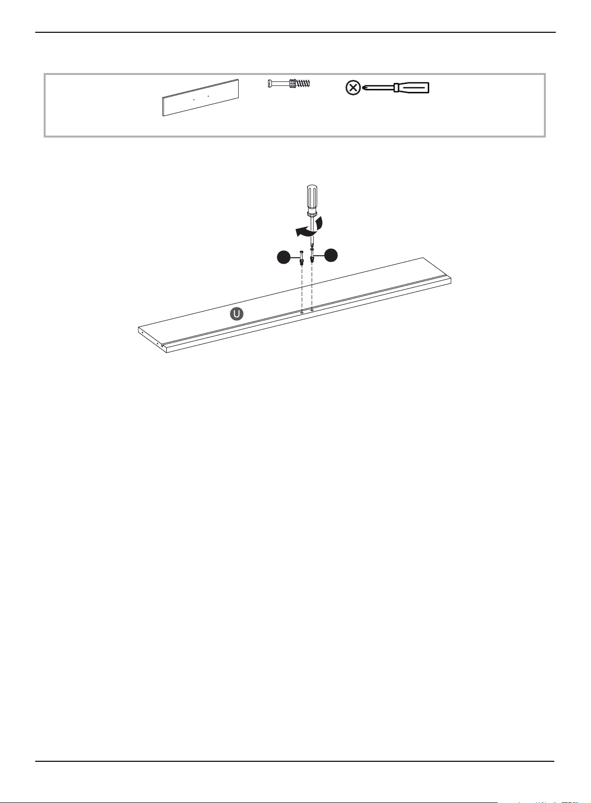
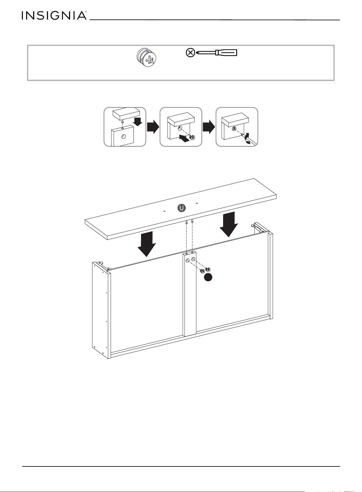
STEP 36:
You need:
• With the groove in the drawer front (U) facing up, insert two cam screws (CC) into the drawer front, then tighten the
screws with a Phillips screwdriver.
CC Cam screw (2)
Phillips screwdriver
U Drawer front (1)
CC
CC
www.insigniaproducts.com
44
58" TV Gaming Stand
STEP 37:
You need:
When you insert a cam lock, position the open end of the lock toward the cam screw, then insert the cam screw into the
cam lock opening.
1 Insert the two cam screws on the drawer front (U) into the drawer support.
2 Insert two cam locks (WW) into the two holes on the drawer support, then tighten the locks with a Phillips screwdriver.
WW Cam lock (2)
Phillips screwdriver
WW
www.insigniaproducts.com
45
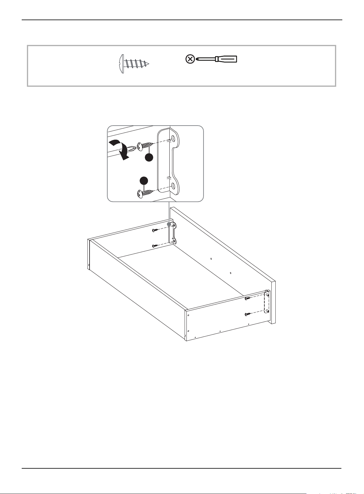
STEP 38:
You need:
1 Align the sides of the drawer so the holes in the brackets align with the holes on the drawer front.
2 Insert two 4.5 × 14 mm screws (QQ) through each bracket and into the drawer front.
3 Tighten the screws with a Phillips screwdriver.
QQ 4.5 × 14 mm screw (4)
Phillips screwdriver
QQ
QQ
www.insigniaproducts.com
46
58" TV Gaming Stand
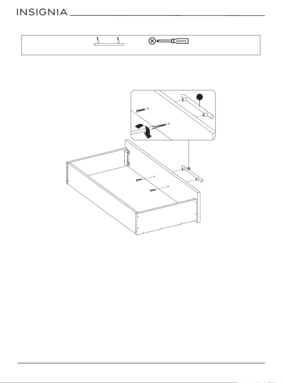
STEP 39:
You need:
1 Remove the screws from the handle (JJ).
2 Align the handle with the holes on the outside of the drawer front, then insert the screws through the back of the
drawer front and into the handle.
3 Tighten the screws with a Phillips screwdriver.
JJ Handle (1)
Phillips screwdriver
JJ
www.insigniaproducts.com
47
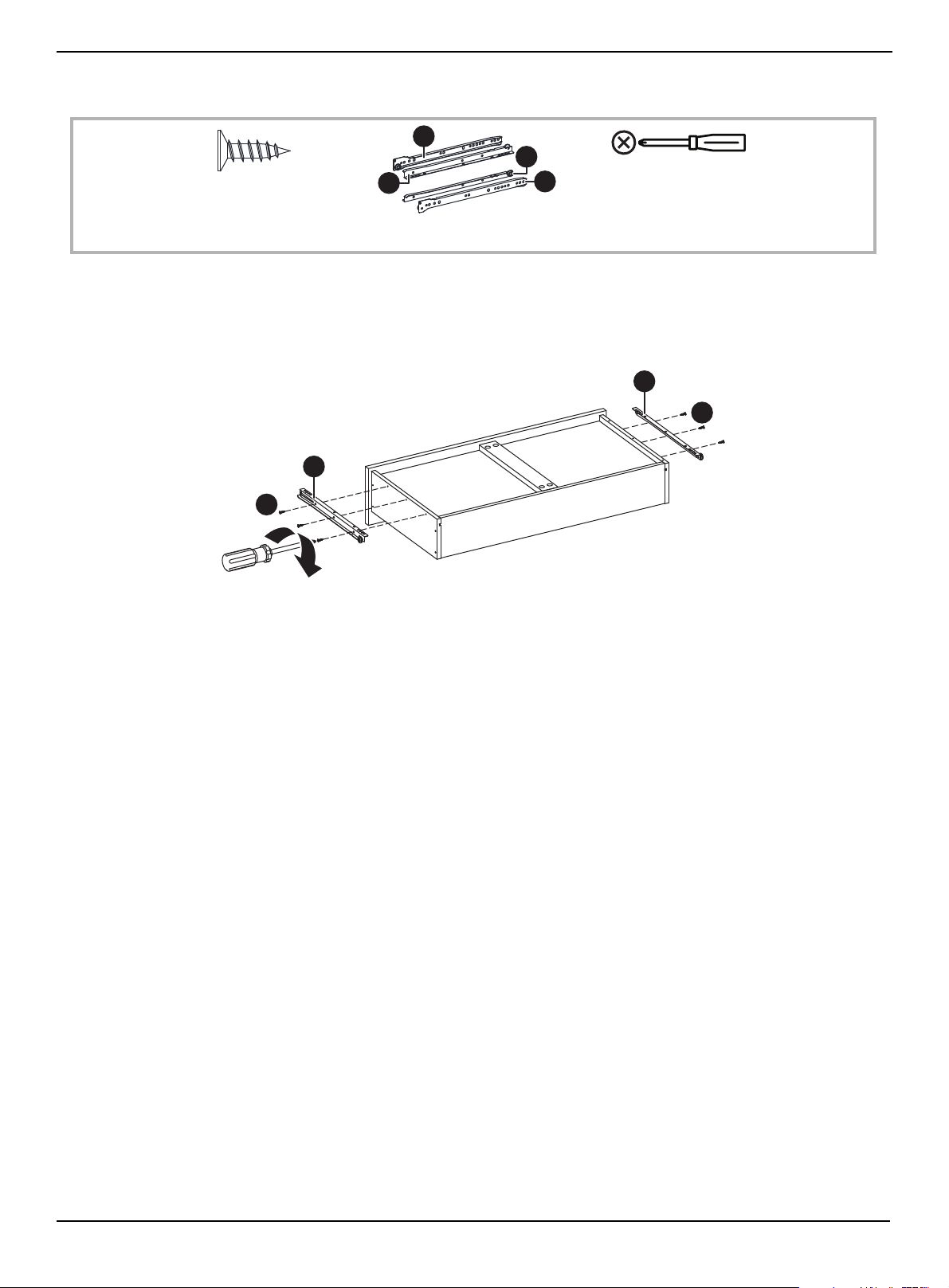
STEP 40:
You need:
1 Insert three 3 × 12 mm screws (AA) into the holes on the DL and DR parts of the rail assembly (BB).
2 Align the screws in the DL and DR parts of the rail assembly with the holes on the outside of the left and right drawer
sides.
3 Tighten the screws with a Phillips screwdriver.
CR
DR
DL
CL
AA 3 × 12 mm screw (6)
BB Left and right rail assembly (2)
Phillips screwdriver
AA
AA
DL
DR
www.insigniaproducts.com
48
58" TV Gaming Stand
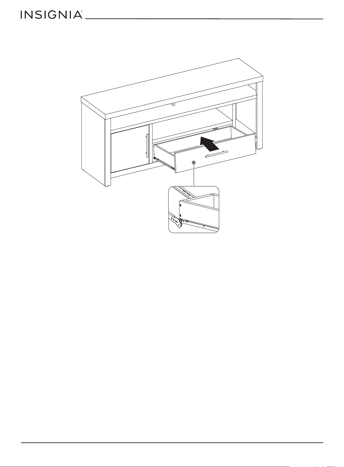
STEP 41:
1 Align the rail assemblies on the drawer with the rails inside cabinet, then slightly lift the drawer up so that the wheels fit
into the slots on the rail assemblies.
2 Slide the drawer into the cabinet.
www.insigniaproducts.com
49
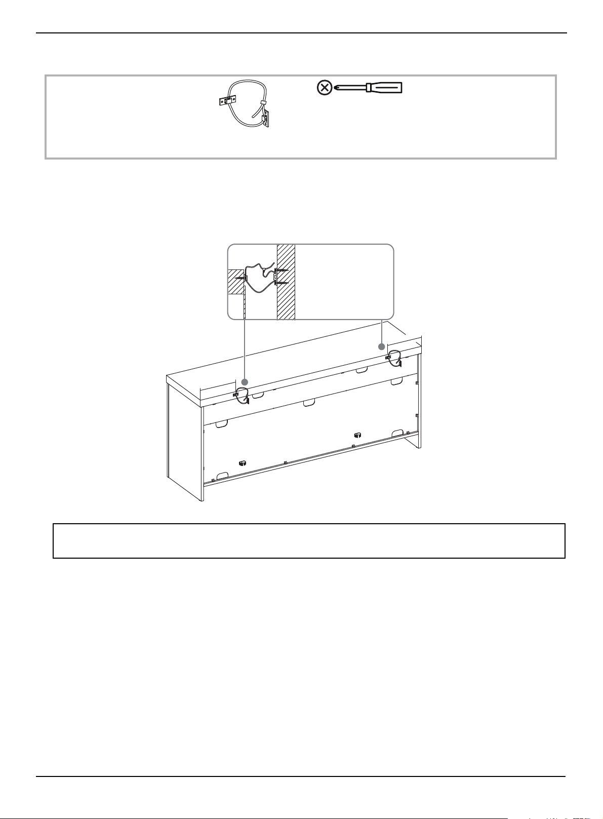
STEP 42:
You need:
1 Insert one screw through one hole on each bracket and into the left and right holes on the top of the back. Tighten the
screws with a Phillips screwdriver.
2 Insert two screws through the two holes on each bracket and into the wall stud. Tighten the screws with a Phillips
screwdriver.
3 Pull the plastic strap on each bracket to secure your TV stand to the wall. Tighten the screws with a Phillips screwdriver.
WARNING: You must install the tip restraint hardware to help prevent any accidents or damage to your TV stand.
We strongly recommend attaching the tip restraint hardware to a wall stud and your stand. For all other wall types, visit your local
hardware store to obtain the correct hardware.
UU Anti-tip bracket with
plastic strap (2)
Phillips screwdriver
7
i
n
.
(
1
8
c
m
)
7
i
n
.
(
1
8
c
m
)
Wall stud
www.insigniaproducts.com
50
58" TV Gaming Stand
Maintaining your TV stand
Your TV stand is designed for year-round use with only minimal cleaning and maintenance.
• Use a soft, clean, cloth that won’t scratch the surface when dusting.
• Use of furniture polish is not necessary. Should you choose to use polish, test first in an inconspicuous area.
• Using solvents of any kind on your furniture may damage the finish.
• Never use water to clean your furniture as it may cause damage to the finish.
• Always use coasters under beverage glasses and flowerpots.
• Liquid spills should be removed immediately, because they may damage the furniture. Use a soft, clean, cloth and blot
the spill gently. Avoid rubbing.
• Always use protective pads under hot dishes and plates. Heat can cause chemical changes that may create spotting
within the furniture.
Caring for wood
We recommend that you keep your TV Stand in a climate-controlled environment.
Temperature and humidity changes can cause fading, warping, shrinking, and splitting of wood. We recommend that you
to keep your stand away from direct sunlight because sun may damage the finish. Correct care and cleaning at home will
extend the life of your TV stand.
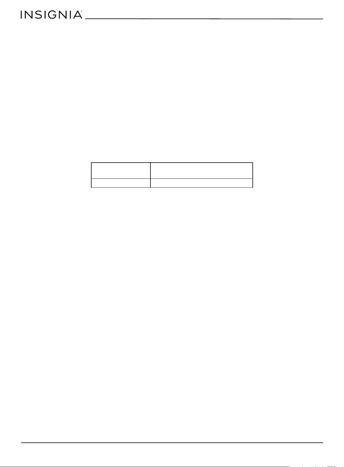
Specifications
Dimensions (WxHxD) 58 x 25.4 x 15.5 in.
(147.3 x 64.5 × 39.4 cm)
Weight 100.3 lbs (45.5 kg)

ONE-YEAR LIMITED WARRANTY
Definitions:
The Distributor* of Insignia branded products warrants to you, the original purchaser of this new Insignia-branded product (“Product”), that the
Product shall be free of defects in the original manufacturer of the material or workmanship for a period of one (1) year from the date of your purchase
of the Product (“Warranty Period”).
For this warranty to apply, your Product must be purchased in the United States or Canada from a Best Buy branded retail store or online at
www.bestbuy.com
or www.bestbuy.ca and is packaged with this warranty statement.
How long does the coverage last?
The Warranty Period lasts for 1 year (365 days) from the date you purchased the Product. Your purchase date is printed on the receipt you received
with the Product.
What does this warranty cover?
During the Warranty Period, if the original manufacture of the material or workmanship of the Product is determined to be defective by an authorized
Insignia repair center or store personnel, Insignia will (at its sole option): (1) repair the Product with new or rebuilt parts; or (2) replace the Product at
no charge with new or rebuilt comparable products or parts. Products and parts replaced under this warranty become the property of Insignia and are
not returned to you. If service of Products or parts are required after the Warranty Period expires, you must pay all labor and parts charges. This
warranty lasts as long as you own your Insignia Product during the Warranty Period. Warranty coverage terminates if you sell or otherwise transfer the
Product.
How to obtain warranty service?
If you purchased the Product at a Best Buy retail store location or from a Best Buy online website (www.bestbuy.com or www.bestbuy.ca), please take
your original receipt and the Product to any Best Buy store. Make sure that you place the Product in its original packaging or packaging that provides
the same amount of protection as the original packaging.
To obtain warranty service, in the United States and Canada call 1-877-467-4289. Call agents may diagnose and correct the issue over the phone.
Where is the warranty valid?
This warranty is valid only in the United States and Canada at Best Buy branded retail stores or websites to the original purchaser of the product in the
country where the original purchase was made.
What does the warranty not cover?
This warranty does not cover:
• Food loss/spoilage due to failure of refrigerator or freezer
• Customer instruction/education
• Installation
• Set up adjustments
• Cosmetic damage
• Damage due to weather, lightning, and other acts of God, such as power surges
• Accidental damage
•Misuse
•Abuse
•Negligence
• Commercial purposes/use, including but not limited to use in a place of business or in communal areas of a multiple dwelling condominium or
apartment complex, or otherwise used in a place of other than a private home.
• Modification of any part of the Product, including the antenna
• Display panel damaged by static (non-moving) images applied for lengthy periods (burn-in).
• Damage due to incorrect operation or maintenance
• Connection to an incorrect voltage or power supply
• Attempted repair by any person not authorized by Insignia to service the Product
• Products sold “as is” or “with all faults”
• Consumables, including but not limited to batteries (i.e. AA, AAA, C etc.)
• Products where the factory applied serial number has been altered or removed
• Loss or Theft of this product or any part of the product
• Display panels containing up to three (3) pixel failures (dots that are dark or incorrectly illuminated) grouped in an area smaller than one tenth
(1/10) of the display size or up to five (5) pixel failures throughout the display. (Pixel based displays may contain a limited number of pixels that
may not function normally.)
• Failures or Damage caused by any contact including but not limited to liquids, gels or pastes.
REPAIR REPLACEMENT AS PROVIDED UNDER THIS WARRANTY IS YOUR EXCLUSIVE REMEDY FOR BREACH OF WARRANTY. INSIGNIA SHALL NOT BE
LIABLE FOR ANY INCIDENTAL OR CONSEQUENTIAL DAMAGES FOR THE BREACH OF ANY EXPRESS OR IMPLIED WARRANTY ON THIS PRODUCT,
INCLUDING, BUT NOT LIMITED TO, LOST DATA, LOSS OF USE OF YOUR PRODUCT, LOST BUSINESS OR LOST PROFITS. INSIGNIA PRODUCTS MAKES NO
OTHER EXPRESS WARRANTIES WITH RESPECT TO THE PRODUCT, ALL EXPRESS AND IMPLIED WARRANTIES FOR THE PRODUCT, INCLUDING BUT NOT
LIMITED TO ANY IMPLIED WARRANTIES OF AND CONDITIONS OF MERCHANTABILITY AND FITNESS FOR A PARTICULAR PURPOSE, ARE LIMITED IN
DURATION TO THE WARRANTY PERIOD SET FORTH ABOVE AND NO WARRANTIES, WHETHER EXPRESS OR IMPLIED, WILL APPLY AFTER THE WARRANTY
PERIOD. SOME STATES, PROVINCES AND JURISDICTIONS DO NOT ALLOW LIMITATIONS ON HOW LONG AN IMPLIED WARRANTY LASTS, SO THE ABOVE
LIMITATION MAY NOT APPLY TO YOU. THIS WARRANTY GIVES YOU SPECIFIC LEGAL RIGHTS, AND YOU MAY ALSO HAVE OTHER RIGHTS, WHICH VARY
FROM STATE TO STATE OR PROVINCE TO PROVINCE.
Contact Insignia:
1-877-467-4289
www.insigniaproducts.com
INSIGNIA is a trademark of Best Buy and its affiliated companies.
*Distributed by Best Buy Purchasing, LLC
7601 Penn Ave South, Richfield, MN 55423 U.S.A.
©2021 Best Buy. All rights reserved

www.insigniaproducts.com
1-877-467-4289 (U.S. and Canada)
INSIGNIA is a trademark of Best Buy and its affiliated companies.
Distributed by Best Buy Purchasing, LLC
7601 Penn Ave South, Richfield, MN 55423 U.S.A.
©2021 Best Buy. All rights reserved.
V3 ENGLISH
21-0653