Loading ...
Loading ...
Loading ...
6 7INSTALLATIONINSTALLATION
Cabinet requirements
This appliance has been designed to ‘slot-in’ to a 600mm
wide gap built-in standard kitchen cabinets. As such the
appliance can be installed to suit the height of the benches
This allows the cooker to integrate well into contemporary
kitchens. The cooker may also be installed at the end of
a line of benches or with a free space on either side.
• Electric hob models must not be installed in a corner;
they must be installed at least 100mm from the
side wall. Gas hob models must be installed with a
minimum clearance of 100mm to side walls made
of unprotected combustible materials.
• For gas models refer to section 6.10.1 in AS/NZS
5601.1 for all relevant clearances.
WARNING
WARNING
This appliance has been tested and approved to the
relevant Australian Standards. It is designed to cook
food, it will get hot. Cabinet materials must be capable
of withstanding 85
o
C. Installation into lower temperature
tolerant cabinetry (e.g. vinyl coated) may result in
deterioration of the low temperature coating by discolour
or bubbling.
Electrolux Home Products cannot accept responsibility
for damage caused by installation into low temperature
tolerant cabinets.
Installation and service warning
WARNING
WARNING
• Only an authorised person must install and
service this appliance (Certificate of Compliance
to be retained).
• In order to avoid a hazard, the installation
instructions MUST be followed.
• In order to avoid the appliance tipping, the anti-tilt
plate MUST be installed.
• Appliances requiring connection to 230 – 240V
MUST be earthed.
• An authorised person should inspect this appliance
every 5 years.
• This appliance must NOT be installed on a base,
box or in a closed cupboard.
• If the electrical supply cord is damaged, a qualified
person MUST replace the cord to avoid a hazard or
void your warranty.
• The unit must be pushed up against the wall on
installation. On gas units check that the gas hose,
if used, has not been kinked during installation.
INSTALLING THE APPLIANCE
(600mm wide product)
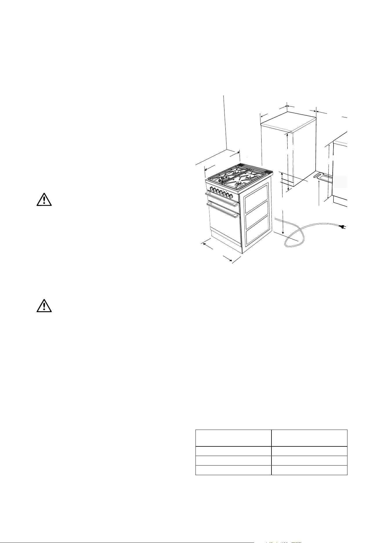
Recommended cabinet design
630mm
600mm
Clearance to side wall
(refer notes)
600mm
minimum
anti-tilt plate
720mm (NOM)
900mm (NOM)
910mm minimum
596mm minimum
1.25m electrical
service cord (if fitted)
Preparing for installation
1. Check that the required services are correctly
positioned (see electrical and gas services
requirements section and cabinet requirements
section).
2. Ensure that cabinetry has correct details (see cabinet
requirements section).
3. Unpack the cooker.
4. Remove the foam pack containing accessories.
5. Remove the internal pack from the oven and position
shelf supports and grill trays.
6. Remove the 2 screws for the splashback from the
rear panel, and fit it to the unit with the same screws.
Following table outlines the distance between the floor
supporting the product and the surface supporting
cooking vessel:
Surface type
(supporting vessel)
Distance (mm)
Ceramic Glass 910
Solid Hotplates 920
Cast Trivets 933
Fitting the anti-tilt plate & stabilising bolt
Cooker Stability
NOTE: To ensure cooker stability, both the anti-tilt plate
and stability bolt MUST be installed on all cookers
(electric and gas).
Installation Sequence
1. The cooker is delivered with the anti-tilt plate. Locate
the anti-tilt plate against the rear wall. If locating
between 2 cupboards, then fit the plate in the centre
of the space. If locating the cooker at the end of a
cupboard, then position the side of the plate 48mm
from the cupboard.
NOTE: If cooker cannot be located against rear
wall, move anti-tilt plate forward to suit.
2. Securely fix the anti-tilt plate to the floor with
appropriate fasteners.
3. Slide the cooker back into the anti-tilt plate so that
rear cover rests against the rear wall.
Then check the height and level of the cooker.
If required, pull the cooker back out and adjust the
levelling feet as required.
4. Cut the cable tie from the stability bolt.
5. Rotate the stability bolt 180 clockwise until it is
pointing to the left like the picture below.
6. The stability bolt should now be able to drop to
the floor.
7. Mark the position for the stability bolt on the floor.
8. Pull the cooker out and drill the bolt hole, using a
6.5mm masonry or wood drill. Minimum 30mm deep
for concrete.
9. Reposition the cooker back into place, then fit the
stability bolt into the drilled hole.
10. Connect gas and electricity supply (refer to
pages following).
11. Fit the kick panel onto the cooker.
48mm to side
of plate
5mm clearance
Rear cover
Anti-tilt
plate
Rear adjustable foot
Stability bolt
Kick panel
ø6.5mm drilled
location hole
Front adjustable feet
Installing splashback
Fit splashback to rear of hob with the two
screws provided
Loading ...
Loading ...
Loading ...